2
INDEX
INDEXINDEX
INDEX
OF CONTENTS
OF CONTENTSOF CONTENTS
OF CONTENTS
1. GENERAL WARNINGS ………………………………………………………
1. GENERAL WARNINGS ………………………………………………………1. GENERAL WARNINGS ………………………………………………………
1. GENERAL WARNINGS ……………………………………………………………………………………………………………………………………
…………………………………………………………………………………………………………………………………………………………
……………………………………………………………………………….3
….3….3
….3
2. FUELS…………………………
2. FUELS…………………………2. FUELS…………………………
2. FUELS…………………………..
....
..………………………
………………………………………………
………………………………………
………………………………
………………………………………………………………………………..
………………………………………………………………..………………………………………………………………..
………………………………………………………………..…………………………...3
…………………………...3…………………………...3
…………………………...3
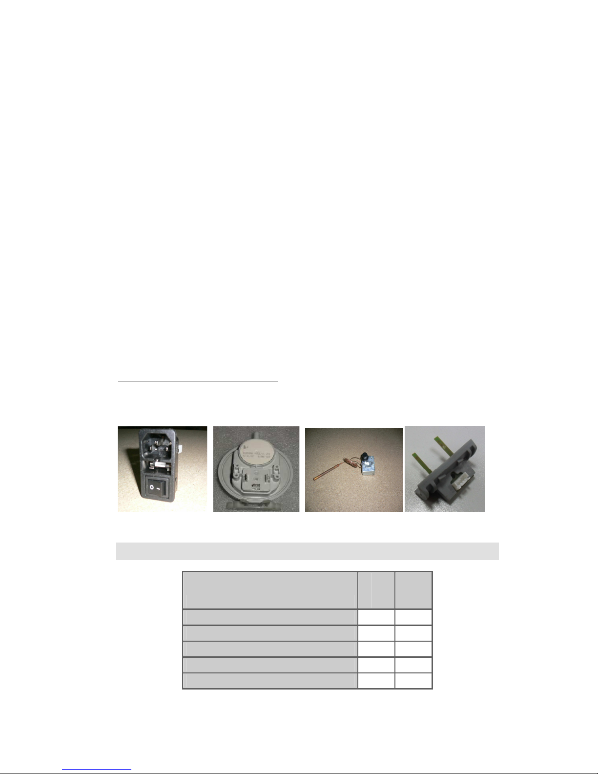
3. SAFETY DEVICES………………………
3. SAFETY DEVICES………………………3. SAFETY DEVICES………………………
3. SAFETY DEVICES………………………..……
..……..……
..…………………………………………………………………………………
…………………………………………………………………………………………………………………………………………………………
………………………………………………………………………………………………………………..4
…………………………………..4…………………………………..4
…………………………………..4
4. TECHNICAL
4. TECHNICAL 4. TECHNICAL
4. TECHNICAL FEATURES
FEATURESFEATURES
FEATURES………………
………………………………
……………………………………………………………………………………………………..
……………………………………………………………………………………..……………………………………………………………………………………..
……………………………………………………………………………………..…………………………….. 5
…………………………….. 5…………………………….. 5
…………………………….. 5
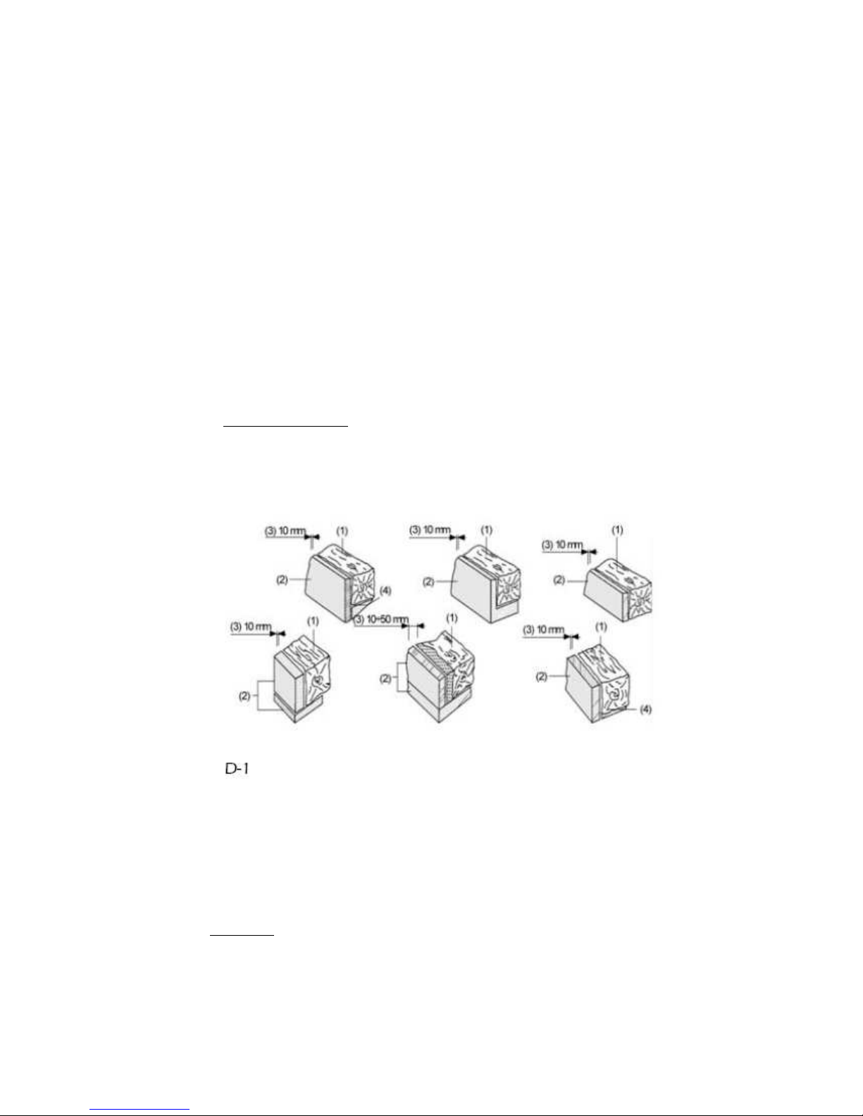
5. INSTALLATION REQUIREMENTS………
5. INSTALLATION REQUIREMENTS………5. INSTALLATION REQUIREMENTS………
5. INSTALLATION REQUIREMENTS……….…
.….…
.………………………………………………………………………..
……………………………………………………………………..……………………………………………………………………..
……………………………………………………………………..…
……
…………………………………. 6
………………………………. 6………………………………. 6
………………………………. 6
5.1. Safety control measures……………………………………………………………………………………………………..…………. 6
5.2. Beams protection………………………………………………………………………………………………………………..……………7
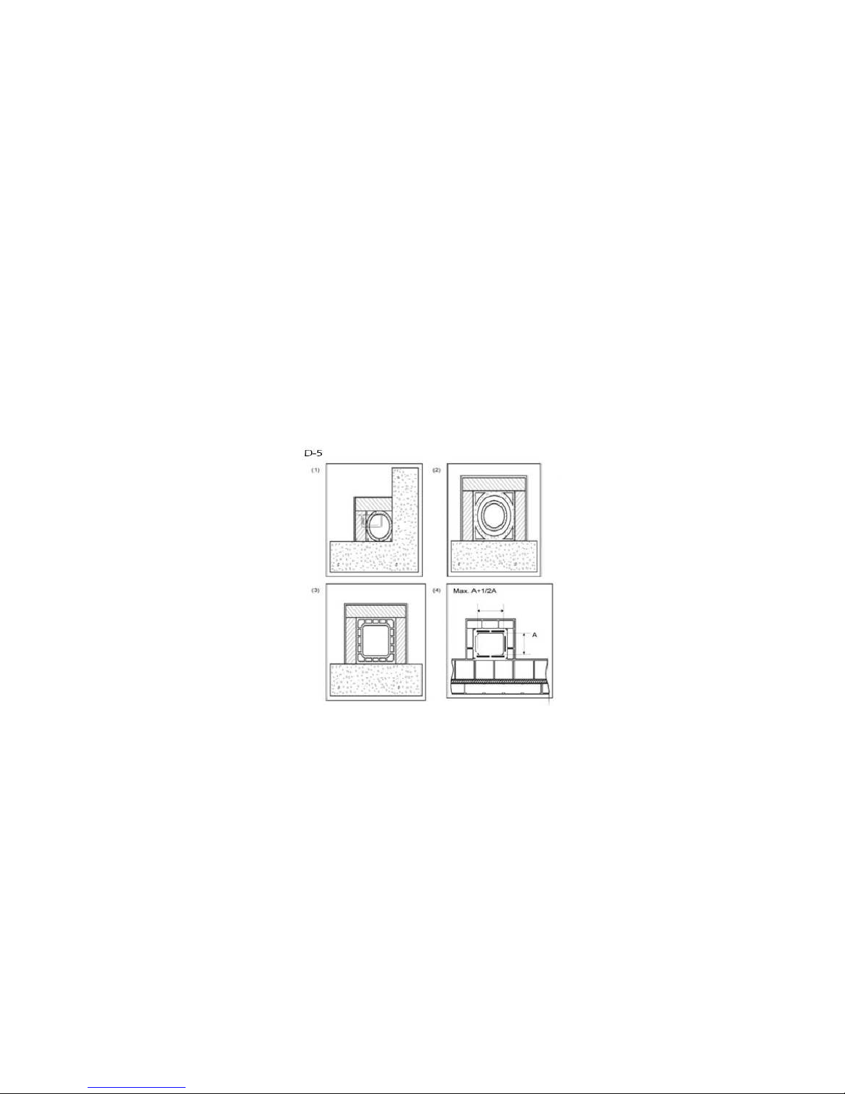
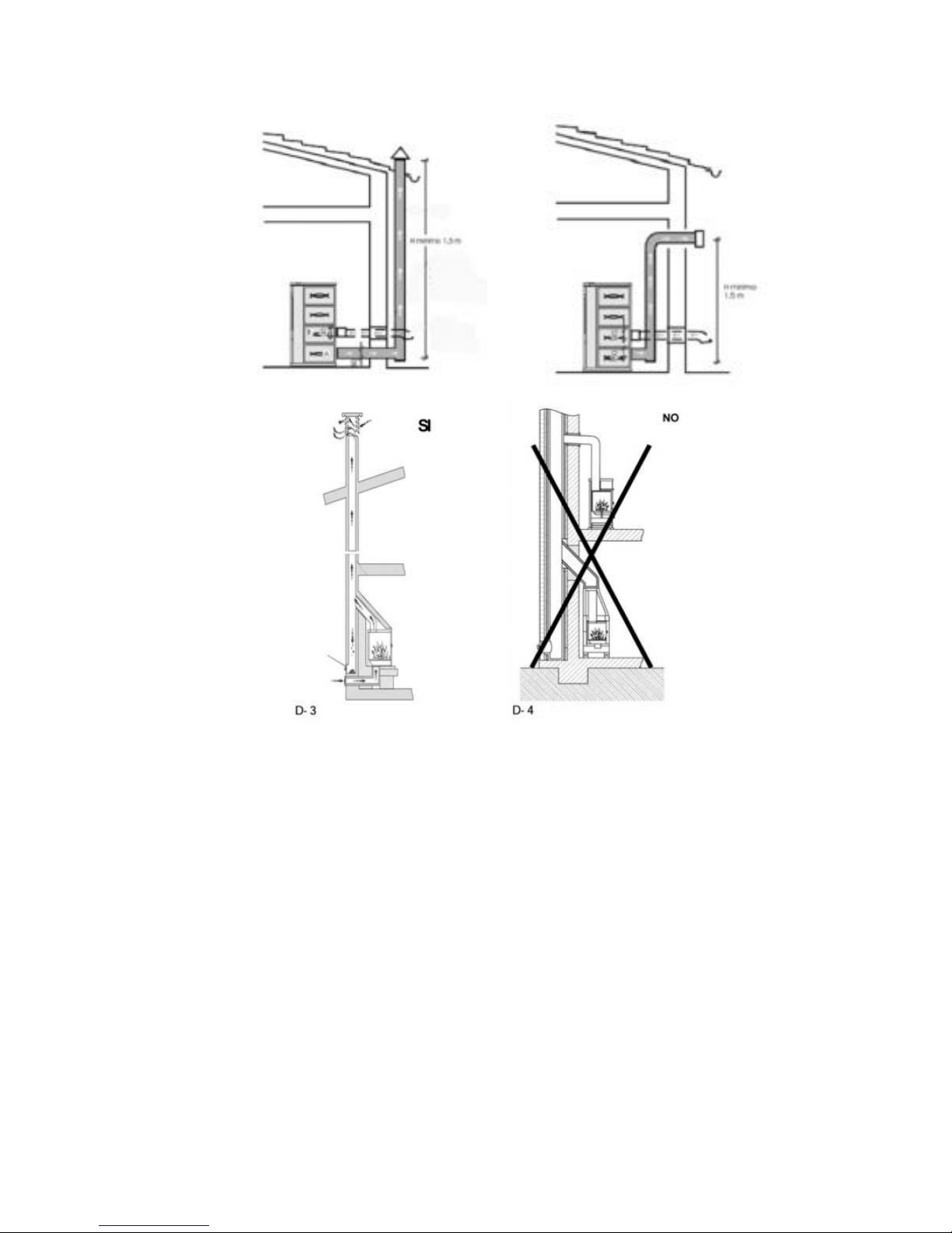
5.3. Chimney………………………………………………………………………………………………………..…………………..……………. 7
5.4. Chimney cowl…………………………………………………………………………………………………………….…………………… 8
5.5. Connection to chimney / Combustion air (air intake)…………………………………………..…………………….8
5.6. Outside air intake………………………………………………………………………………………………………………………….….9
6.
6.6.
6.
STARTING
STARTINGSTARTING
STARTING
U
UU
U …………
……………………
……………
……
…………………
………………………………
…………………..
…..…..
…..……………………………………
…………………………………………………………………………
……………………………………………………
………………………………
…………………………………………………………………………
……………………………………………………………………………………………………………………
……………………………………………………………....
…....…....
…....9
99
9
7.
7. 7.
7. USUAL O ERATION
USUAL O ERATIONUSUAL O ERATION
USUAL O ERATION……………
…………………………
…………………………………………………
…………………………………………………………………………
…………………………………………………………………………………………………………………….
……………………………………………………………………………….……………………………………………………………………………….
……………………………………………………………………………….…….10
…….10…….10
…….10
8. MAINTENANCE AND CARE…………………………………
8. MAINTENANCE AND CARE…………………………………8. MAINTENANCE AND CARE…………………………………
8. MAINTENANCE AND CARE…………………………………………………………………………………………………………
………………………………………………………………………………………………………………………………………………
………………………………………………………………………………
………………
……….…………10
.…………10.…………10
.…………10
8.1. Burn pot cleaning…………………………………………………………………………………………………………..……………..10
8.2. Ash pan cleaning………………………………………………………………………………………………………………………… 11
8.3. Ash pan and burn pot door joints………………………………………………………………………………………….…...11
8.4. Chimney cleaning…………………………………………………………………………………………………..……………….….. 11
8.5. Glass cleaning…………………………………………………………………………………………………………………………….….11
8.6. Exterior cleaning ………………………………………………………………………………………….……………………………....12
8.7. Seasonal shutdowns……………………………………………………………………………………….…………………………….. 12
9
99
9
DIS LAY
DIS LAYDIS LAY
DIS LAY
O ERATION
O ERATIONO ERATION
O ERATION
................................
................................................................
................................................................
................................................................
................................................................
................................................................
................................................................
................................................................
.............................................................
..........................................................
.............................
15
1515
15
9.1
Display general information.................................................................................................................................................... 15
9.2
Display keys running.................................................................................................................................................................. 16
9.3
Remote control general infomation. .................................................................................................................................... 16
9.4
Menu option ................................................................................................................................................................................. 17
9.4.1
User menu ..................................................................................................................................................................... 17
9.4.2
Menu 1. .......................................................................................................................................................................... 17
9.4.3
Menu 2. Clock ............................................................................................................................................................... 18
9.4.4
Menu 3. rogramme Adjustment. ........................................................................................................................ 18
9.4.5
Menu 4. Language selection .................................................................................................................................. 25
9.4.6
Menu 5. Stand-by mode ........................................................................................................................................... 26
9.4.7
Menu 6- Sonorous mode .......................................................................................................................................... 26
9.4.8
Menu 7. Initial charge ................................................................................................................................................ 26
9.4.9
Menu 8- Stove stage ................................................................................................................................................... 26
9.5
User Mode ..................................................................................................................................................................................... 28
9.5.1
Starting up stove ......................................................................................................................................................... 28
9.5.2
Operation stove ........................................................................................................................................................... 28
9.5.3
Consigned ambiance temperature changing .................................................................................................. 29
9.5.4
User fixed temperature reached by the ambiance temperature… ............................................................ 29
9.5.5
Burn pot automatic cleaning .................................................................................................................................. 29
9.5.6
Shutdown stove........................................................................................................................................................... 30
9.5.7
Shutted off stove. ........................................................................................................................................................ 30
9.5.8
Re-starting up stove. ................................................................................................................................................... 30
9.6
What happens if…? ..................................................................................................................................................................... 30