Bronpi Julieta Mounting instructions

MOD. JULIETA
“TECNOLOGÍA OASYS (Optimum Air System)”.
Please read attentively these instructions before installation, use and maintenance.
The instructions guide is an integral part of the product.
INSTALLATION INSTRUCTIONS AND USER GUIDE

1GENERAL WARNINGS .............................................................................................................................................................4
2FUELS........................................................................................................................................................................................... 4
3SAFETY DEVICES ....................................................................................................................................................................... 4
4TECHNICAL FEATURES ............................................................................................................................................................6
5INSTALLATION REQUIREMENTS ........................................................................................................................................... 6
5.2 Timber beams protection............................................................................................................................................................7
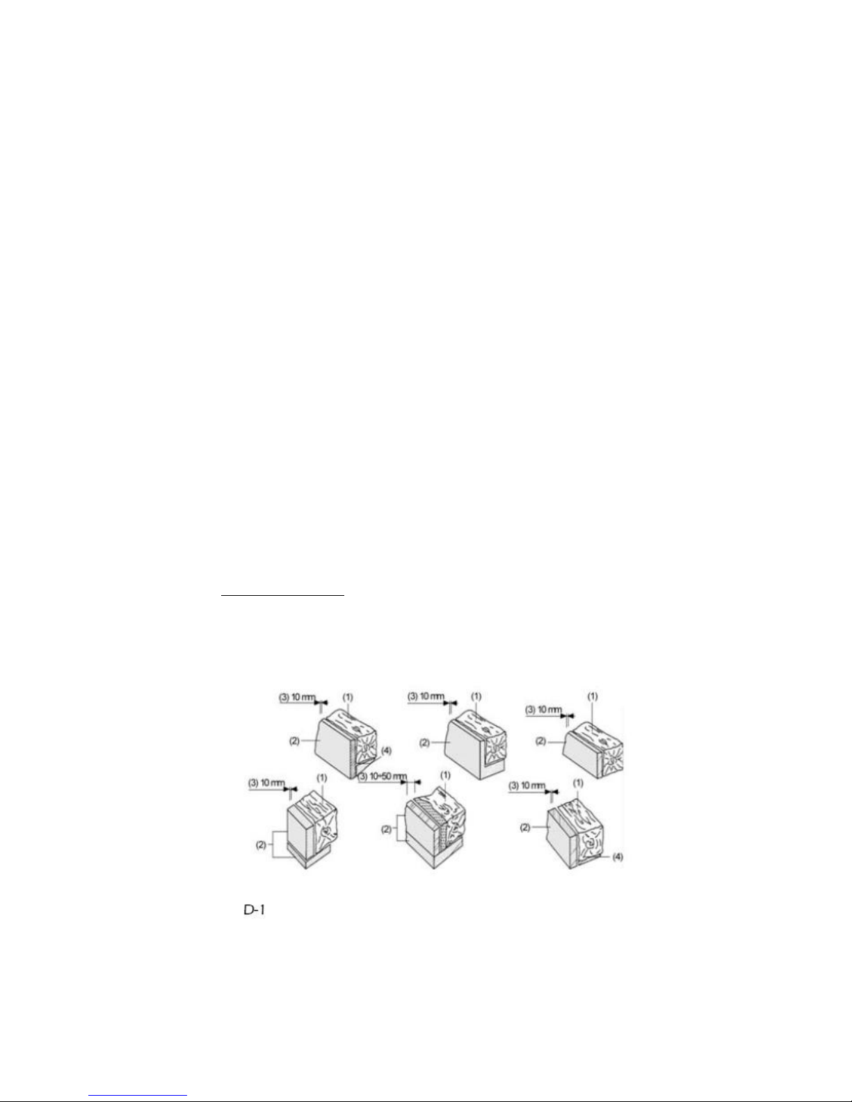
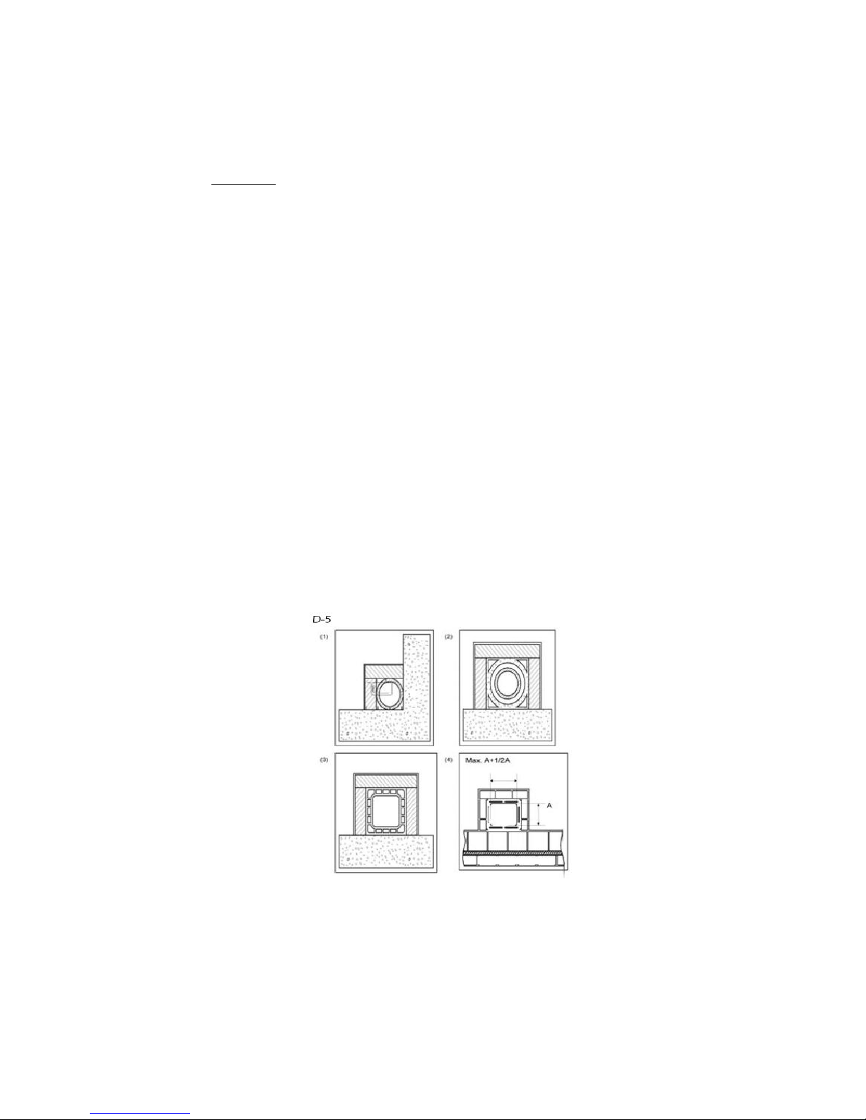
5.3 The chimney ....................................................................................................................................................................................8
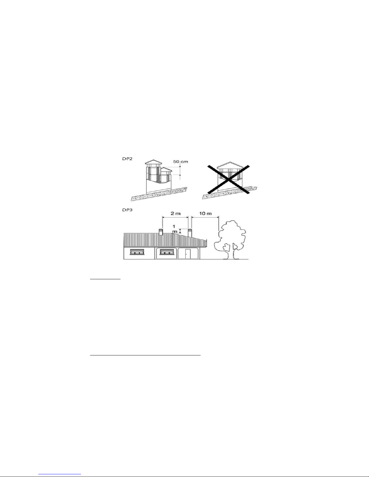
5.4 Chimney cowl...............................................................................................................................................................................10
5.5 Connection to chimney / Combustion air (air intake)...................................................................................................10
5.6 Outside air intake........................................................................................................................................................................11
6STARTING UP ...........................................................................................................................................................................12
7USUAL OPERATION ...............................................................................................................................................................12
8MAINTENANCE AND CARE..................................................................................................................................................13
8.1 Burn pot cleaning .......................................................................................................................................................................13
8.2 Scrapers using (ONLY FOR 10 KW MODELS) ...................................................................................................................13
8.3 Ash pan cleaning (ONLY FOR 10 KW MODELS) .............................................................................................................13
8.4 Ash pan and burn pot door joints ........................................................................................................................................13
8.5 Chimney cleaning.......................................................................................................................................................................13
8.6 Glass cleaning ..............................................................................................................................................................................13
8.7 Exterior cleaning .........................................................................................................................................................................13
8.8 Seasonal shutdowns..................................................................................................................................................................14
9DISPLAY OPERATION.............................................................................................................................................................15
9.1 Display general information....................................................................................................................................................15
9.2 Display keys running..................................................................................................................................................................16
9.3 Remote control general information ...................................................................................................................................16
9.4 Menu option .................................................................................................................................................................................17
9.4.1 User menu .....................................................................................................................................................................17
9.4.2 Menu 1............................................................................................................................................................................17
9.4.3 Menu 2. Clock...............................................................................................................................................................18
9.4.4 Menú 3. Programme Adjustment .........................................................................................................................18
9.4.5 Menu 4. Language selection ..................................................................................................................................26
9.4.6 Menu 5. Stand-by mode ...........................................................................................................................................26
9.4.7 Menu 6- Sonorous mode..........................................................................................................................................26
9.4.8 Menu 7. Initial charge................................................................................................................................................26
9.4.9 Menu 8- Stove stage...................................................................................................................................................27
9.5 User mode .....................................................................................................................................................................................28
9.5.1 Starting up stove .........................................................................................................................................................29
9.5.2 Operation stove...........................................................................................................................................................29
9.5.3 Consigned ambiance temperature changing ..................................................................................................30
9.5.4 User fixed temperature reached by the ambiance temperature…............................................................30
9.5.5 Burn pot automatic cleaning..................................................................................................................................31
9.5.6 Shutdown stove...........................................................................................................................................................31
9.5.7 Shutted off stove .........................................................................................................................................................31
9.5.8 Re-starting up stove....................................................................................................................................................32

9.6 What happens if…?.....................................................................................................................................................................32
9.6.1 Pellet fuel do not light...............................................................................................................................................32
9.6.2 Electrical supply failure (Back out)........................................................................................................................32
9.7 Alarms .............................................................................................................................................................................................33
9.7.1 Alarm smokes temperature probe........................................................................................................................33
9.7.2 Alarm smoke excess temperature.........................................................................................................................33
9.7.3 Alarm starting up failure...........................................................................................................................................33
9.7.4 Alarm shutdown during work phase..................................................................................................................34
9.7.5 Alarm damaged extraction smokes fan..............................................................................................................34
10 GENERAL MEASURES.............................................................................................................................................................36

1GENERAL WARNINGS
The heater installation has to be carried out in accordance with the local and national regulations, including
all regulations referred to national or European standards.
All heaters produced in our company are made controlling all the pieces and trying to protect both the user
and the fitter, to avoid possible accidents. We also recommend to the authorized technical fitters, to pay
special attention on electrical connections every time they carry out an operation, especially at the bare part of
cables, which should never be out of the connections box so that dangerous contacts are avoided.
The installation must be executed by authorized personnel, whose will have to supply the buyer an
installation conformity declaration, to assume full responsibility for the definitive installation and keep the
product in working order. Bronpi Calefacción S.L. will not assume any responsibility in case of absence of
fulfilment such precautions.
The manufacturer will be exempted of any responsibility opposite to damages caused to third due to incorrect
installation or bad use of the device.
To guarantee an accurate operation of the appliance the components should only be replaced for original
spares by an authorized technician.
The maintenance of the device must be carried out at least once a year, by the Authorized Technical Service.
For a major safety it is necessary to bear in mind:
Don’t touch the heater being barefooted or with humid parts of the body.
The door of the unit must be closed during the operation.
It is prohibited to modify the safety devices or regulations of the unit without the authorization
of the manufacturer.
Avoid the direct contact with the parts of the appliance that tend to reach high temperatures
during the operation.
2FUELS
WARNING!!!
USING A BAD QUALITY PELLET FUEL OR ANY OTHER MATERIAL DAMAGES THE OPERATION OF THE
HEATER AND COULD DETERMINE THE EXPIRATION OF THE WARRANTY IN ADDITION TO EXEMPTING
RESPONSIBILITIES FROM THE MANUFACTURER.
Pellet fuel used has to be in accordance with the characteristics described in the norms:
Ö-Norm M 7135
DIN plus 51731
UNI CEN/TS 14961
Bronpi Calefacción recommends using pellet fuel 6 mm in diameter.
• PELLET FUEL STORAGE
To avoid combustion problems it is necessary to preserve the pellet fuel on a dry environment.
• PELLET FUEL SUPPLY
For supplying the heater, you have to open the hopper lid at the top of the appliance pouring directly into it
the pellet fuel, taking care not overfilling the hopper.
3SAFETY DEVICES
• TURNING ON FAILURE
If during the ignition stage the flame does not take place, the appliance will show in the display “no ACC”. If
you try to light the machine again, in the display you will read “ATTE“which means “wait“.
This function serves to remember that, before carrying an ignition out, it is necessary to verify that the burn
pot is completely clear and clean.
• BREAKDOWN ON THE WARM AIR DISTRIBUTION FAN
In case that ventilation stops for any reason, the heater stops automatically, avoiding the overheating (not
included on hydro models).

• BREAKDOWN ON THE SMOKE VACUUM CLEANER
If the extractor stops, the electronic card blocks automatically the pellet fuel supply.
• BREAKDOWN ON THE PELLET FUEL LOADING ENGINE
If the differential engine stops, the heater keeps on working until it does not reach the minimal functioning
temperature and stops.
• ELECTRICAL CURRENT TEMPORARY FAILURE
After a brief absence of current, the heater turns on again. When electricity is missing, the heater can produce
a limited quantity of smoke inside the house during an interval from 3 until 5 minutes. THIS DOES NOT
ENDURE ANY RISK FOR THE SAFETY. That’s why Bronpi advises whenever it is possible to connect the pipe of
entry of primary air with the exterior of the housing to ensure that the heater could not detach smokes after
the above mentioned absence of current.
• ELECTRICAL PROTECTION
The heater is protected against sudden electricity oscillations by means of a general fuse placed on the back
part. (2nd 250V Slowed down). (To see photo 1).
• EXIT SMOKE PROTECTION
An electronic pressureswitch foresees to block the operation of the heater, if sudden change of pressure takes
place inside the combustion chamber (door opening, damage of engine of smokes extraction…) the heater
will go into the alarm mode. (Photo 2)
• PROTECTION BEFORE THE PELLET HIGH TEMPERATURE (80th C)
In case of overheating inside the hopper, this device blocks the appliance operation. The manual
reestablishment must be carried out by an authorized technician. (Photo 3).
The reestablishment of this safety device is not considered by the warranty, unless the assistance centre may
demonstrate the presence of a defective component.
FLOW SENSOR (Oasys Technology)
Your stove is provided with a flow sensor (Picture 4), which is placed on the primary air suction pipe; it detects
the correct circulation of the combustion air and the smokes discharge. In case of an incorrect smoke
discharge (as consequence of the incorrect entrance and exit of smokes) it sends the stove a sign of blockage.
OASYS TECHNOLOGY (Optimum Air System) obtains a constant combustion, regulating automatically the
throw according to the characteristics of the smoke pipe (curves, length, diameter etc.) and the environmental
conditions (wind, humidity, atmospheric pressure etc.). For this the installer has to introduce on the technical
menu the geographic height of the place where the stove is installed.
Picture 1 Picture 2 Picture 3 Picture 4

4TECHNICAL FEATURES
Features
Julieta
Weight (Kg.)
128
Height (mm)
1099
Width (mm)
528
Depth (mm)
598
Smoke discharge pipe diameter (mm)
80
Aspiration air pipe diameter (mm)
40
Volume max. warning (m3)
212
Nominal power capacity
88
Reduced power capacity
88
Global thermal power max. (Kw.)
8.5
Useful thermal power max. (Kw)
8.5
Useful thermal power min. (Kw)
3.5
Pellet consumption min. Kg/h
0.83
Pellet consumption max. Kg/h
2
Hopper capacity (Kg.)
21
Autonomy min/max (h)
25/10.5
Recommend shot to useful power max. (Pa)
~ 12
Recommend shot to useful power min. (Pa)
~ 10
Electrical consumption (W)
150-200
Electrical consumption during the ignition (W)
300
Cast iron interior
No
Automatic ignition
Si
Security pellet thermostat
Si
Remote control
SI
Weekly programmer
Si
5INSTALLATION REQUIREMENTS
The way to install a new product is directly related to the safety and efficiency of the appliance. This is the
reason why all stoves and appliances should always be installed only by suitable trained and qualified heating
engineers. Serious damages to the appliance, as well as personal injuries, may occur if the device is installed
incorrectly.
Prior to installation, the following measures must be taken:
Check the floor is strong enough to support the weight of the unit, and if it is made of
flammable materials (wood, etc) or susceptible materials to high temperatures.
Make sure the ambience where the device will be installed has suitable ventilation (presence of
air capture).
Avoid installation in rooms with shared ventilation vents, hoods (with or without extractors),
type B gas appliances, gas bottles or other appliances which use may affect the draw to the
appliance

Make sure the chimney and the flue system/flue liner used is accurate for the product.
Make sure each appliance has it own chimney. The same chimney can not be used for more
than one appliance.
We suggest contacting your chimney sweep to check whether chimney connexion and the combustion air
flow on the installation place.
5.1. Safety control measures
During the appliance installation, for certain risks it is necessary to bear in mind the following safety measures:
a) Keep all heat sensitive or flammable materials at least 150 cm away from the device (furniture,
curtains, clothing, etc.)
b) When the device is going to be installed on flooring that is not completely insulated, a
fireproof base (such as a suitable constructional hearth and superimposed hearth) must be
installed.
c) Do not install the device close to flammable or heat-sensitive walls.
d) The heater must only be used with the ash pan in place.
e) We recommend the installation of a carbon monoxide detector in the room where the device
is fitted.
Ash must be collected in an airtight, fireproof container.
The fire must never be lit in the presence of gases or vapours such as linoleum glue, petrol, etc. Never leave
flammable objects near the fire.
WARNING! Both the firebox and the glass become extremely hot and should never be touched directly.
If there is a fire either in the device or within the chimney then:
a) close the loading door.
b) close the air vents.
c) extinguish the fire using fire extinguishers of dioxide of carbon (CO2 powder).
d) call for the fire brigade immediately.
DO NOT TRY TO PUT THE FIRE OUT WITH WATER!!!
5.2
Timber beams protection
Given the amount of heat produced by the device, special attention must be taken to protect nearby wooden
beams. When designing the fireplace both the proximity of the beams to the exterior surfaces on the fire, and
the heat emitted from the glass door need to be taken into account. The exterior faces of combustible beams
must not be subjected to temperatures exceeding 65ºC.
Some suggested solutions to this matter appear on the following drawing.
1-Beam;
2-Refractory Material Isolation;
3-Pothole;
4-Metallic protection;

PLEASE NOTE:
The manufacturer admits no liability whatsoever for any malfunction in any of its products if correct
installation procedures are not followed.
5.3
The chimney
The chimney has a fundamental importance for the correct operation of the device and has two purposes:
It channels smoke and gasses harmlessly away from the room
It provides a sufficient draw to keep the fire alight.
It is essential that the chimney is correctly built and is subject to regular maintenance to keep it in good order.
(Most complaints of incorrect functioning of the device are due to an inadequate draw or other chimney
malfunction).
The correct functioning of the device requires the chimney/flue conditions:
The internal section of the chimney should preferably be circular
The entire height of the chimney must be heat insulated correctly in order to avoid problems
with smoke condensation, this is especially so in cases of external chimneys.
If metal flue pipes are fitted to form an external chimney, only twin-wall insulated flue pipes
should be used in order to avoid problems with condensation.
The chimney should have an even diameter throughout its length (i. e. no increases or
reductions in the volume of the chimney) and it should be vertical and have no bends of over
45º within it.
Any existing chimney must be swept before installation of the device.
Technical data in the flue manufacturer’s instruction manual must be complied with.
The optimum draw of a chimney should be between 10 and 14 on the Pascal scale. A lesser value (weak
draw) results in incomplete combustion which produces carbon deposits and excess smoke production. It can
also lead to smoke leaks and increases in temperature within the appliance which can (in turn) cause serious
damage to the structural components of the product.
Too much draw in the chimney can result in the fire burning too rapidly and too much heat being passed
through the tubing.
Chimneys constructed from fibrous cement, galvanised steel and chimneys with rough or porous interior
surfaces are forbidden and lead to poor functioning of the equipment. Some solutions to this problem are
suggested on the following drawing.
(1) Pavement chimney AISI 316 with double wall insulated with resistant material to 400º C. Efficiency 100 %
ideal.
(2) Traditional chimney of clay section squared in hollows. Efficiency 80% ideal.
(3) Chimney of refractory material with double insulated wall and exterior revetment of lightened concrete.
Efficiency 100% ideal.
(4) Avoid chimneys with rectangular interior section which relation is different from the drawing. Efficiency
40% mediocre.

Each stove must have it own dedicated chimney to eliminate fumes and gasses. The same chimney must
never be used for more than one appliance. (See drawings D3 and D4 (Page 14). The minimum cross-
sectional area of the chimney must be 4 dm2 (e.g. 20 x 20 cm) for appliances having flue pipes with a
diameter less than 200 mm or 6,25 dm2 (e.g. 25 x 25 cm) for the appliances having flue pipes with a diameter
over 200 mm.
If a section of the chimney is too large to be heated adequately, this will cause problems with the appliance: to
avoid this we recommend installing a flue pipe for the entire length of the chimney.
If any section of the chimney is constructed, it will reduce the draw on the fire.
The flue pipe must be installed an adequate distance from any flammable material and have correct insulation
or a sufficient air gap. Flue pipes must never be installed inside air ventilation channels. Moveable or fixed
openings must not be made in the chimney for the connection of any other device.
See DP2, DP3 and DP4.

(1) Axis top
(2) Roof
5.4
Chimney cowl
The pull on the flue pipe depends on the suitability of the chimney cowl. It is essential that the sectional area
of the cowl exit is at least twice (preferably 2.5 times) that of the flue pipe. The termination of the flue pipe
must always exceed the top level of the roof so that the chimney is able to discharge even in windy conditions
(DP7)
Any cowl must comply with the following conditions:
The outlet area must be at least double that of the interior section of the chimney.
It must be constructed to prevent the entry of rain, snow or foreign bodies
It must have easy access for inspection, maintenance and cleaning.
The interior section must be equal to the chimney one.
5.5
Connection to chimney / Combustion air (air intake)
The immediate connection of the device to the chimney/flue system must be made using stainless steel flue
pipe.
Flexible tubing must never be used as the joints will be subject to damage and lead to smoke leaks.
The flue pipe must be hermetically sealed to the device and have a maximum bend of 45 degrees. This will
avoid excessive condensation during lightning, prevent soot deposits and avoid impeding the release of
smoke from the fire box. If the seal is not properly connected, the stove will not function properly.
The inside diameter of the connection tube must equal the exterior diameter of the flue pipe. Flue pipes
conforming to DIN 1298 will ensure this. The pull on the chimney must be between 10 and 14 Pa.
The measuring must always be done with the device hot (nominal calorific output).
If the pull is over 15 Pa, it will be necessary to reduce it by installing an additional regulator.

IMPORTANT!!!
Where metal flue pipes are used, it is essential that they are appropriately insulated (insulated fibre cladding)
to avoid damaging the masonry in the chimney. When the device is being installed in an existing chimney, it
must be sealed around the flue pipe exit at the bottom entrance to the chimney with a pre-formed metal plate
or other fireproof material able to withstand very high temperatures.
References
Flammable Objects
Not flammable objects
A
1500
800
B
1500
150
C
1500
400
5.6
Outside air intake
It is essential that the room in which the device is installed has sufficient fresh air intake and air circulation to
keep a good draw on the fire and to re-oxygenate the room even with the doors and windows closed.
The air inlet must be positioned so that it cannot be obstructed.
It must take fresh air directly into the room where the device is installed, be protected by grille
and have an area of at least 100 cm2.
Industrial fume exit of pre-
fabricated elements permits
excellent fume extraction.
Handmade fume exit. Correct
section of exit must be twice as
the inside section of the
chimney. Ideal 2,5 times.
Fume exit for steel chimney
with inside cone.

Air inlets shouldn’t draw air from adjacent rooms such as garages, lavatories, boiler rooms, etc,
but should take air directly from outside the building
The stove previews the necessary air intake for the combustion on it back (40 mm diameter). It is important
not to block this air intake, and to respect the distance recommended from the walls and furnishings nearby.
It is recommended but not obligatory connecting the primary air intake of the stove to the exterior. Regarding
the material of the connection pipe, it is not necessary to be metallic, it could be made of another material
(PVC, aluminium, polyethylene, etc), note that for this line air will circulate with the outside ambiance
temperature.
6STARTING UP
The lightning of this type of devices is completely automatic therefore you must not introduce in the burn pot
any type of material for its lightning.
During the first lightning it may happen that the device has finished the lightning cycle and does not appear
the fire. If this happens the device goes on automatically to state of alert. This is due to the fact that the feeder
of the fuel is empty and needs a time to fill. To solve this problem light again the heater again until the fire
appears.
It is prohibited the use of all the liquid, such substances like, for example, alcohol, gasoline, oil and similar. The
use of the above mentioned substances will cause the loss of the guarantee.
During its lifetime, the product will be subject to alternating cycles of heating and cooling both
on a daily basis as well as cycles of intense use or total rest depending on the season.;
Before fully settling in, the device must be subjected to several cycles of use so that the materials
and paintwork can settle in and bind flexibly;
In particular it may be noticeable on first lightning the stove that there is smell of hot metal and
fresh paint. During manufacture the paint has already been heat treated to extremely high
temperatures but before binding completely with the metal surface it needs to be run at
sustained temperatures of 200 degrees for long periods and on several occasions.
Therefore, it is important to adopt these small precautions in starting phase:
1. Keep the room well ventilated to avoid a build up of fumes.
2. For the first few lightings of the fire, take care not to overload the fire box with fuel and
preferably keep it lit for 6-10 hours continuously.
3. Repeat this procedure at least four or five times.
4. During the first few uses, nothing should be placed on the device or the paintwork, nor
should painted surfaces be touched whilst heating up.
5. Even after this initial phase of “running in” is complete, the appliance should be treated like car
engines i.e. avoid both overloading and overheating.
7USUAL OPERATION
As well as regulating the air intake, the draw on the flue will affect the rate of combustion and the heat
output of the device. A strong pull on the chimney will need a reduction on the draw to the fire, while a weak
pull will require extra attention to the setting of the air intake controls.
Check if the draw to the fire is correct by looking at the colour of smoke being emitted. It should be
transparent. If it is white, it means that the controls have not been set correctly or the used pellet is too wet. If,
on the other hand, the smoke is black or grey, it means that the fuel is not being completely burned and the
secondary air intake must be increased.

8MAINTENANCE AND CARE
The maintenance operations guarantee that the product works correctly during long time. If you don’t do it, it
can damage the device.
8.1
Burn pot cleaning
The cleaning of the burn pot must be carried out every day.
Extract the burn pot and to unblock the orifices with corresponding poker, which is given
together with the heater.
Use a vacuum cleaner to eliminate the ash of the burn pot
Vacuum the ash deposited in the accommodation of the burn pot.
8.2
Scrapers using (ONLY FOR 10 KW MODELS)
The cleaning of fire box allows guaranteeing that thermal efficiency is constant during long time. This type of
maintenance must be carried out at least once a day. To carry out it is enough to use the corresponding
scrapers, which are in the top part of the heater, realizing a lower movement up to down and vice versa
repeatedly.
8.3
Ash pan cleaning (ONLY FOR 10 KW MODELS)
The ash pan must be emptied when it is necessary. The heater can’t be lightening without the ash pan inside.
8.4
Ash pan and burn pot door joints
The joints guarantee the airtightness of the heater and consequently the good functioning of the device.
It is necessary to control them periodically: if they are worn out or damaged they will have to be replaced
immediately.
These operations can only be carried out by an authorized technician.
For the correct functioning of the heater, an authorized technical service must proceed to its maintenance at
least once a year.
If the power wire is damaged, it has to be replaced by service of technical assistance or, in any case, by a
qualified technician, avoiding useless risks.
8.5
Chimney cleaning
During normal use, the device will not suffer any damage. When pellet is burnt slowly, tar and gasses are
emitted which (when combined with normal humidity) lead to creation of soot. An excessive build-up of soot
in the chimney can cause problems with the smoke discharge and a risk of fire.
Cleaning should be undertaken by a professional chimney-sweep and should be carried out when the device
is cold. It is advisable to check out the condition of the device at the same time and keep a note of dates on
which this work has been carried out
8.6
Glass cleaning
IMPORTANT:
The glass must only be cleaned when it is completely cold to avoid the possibility of shattering .Commercial
product may be used or alternatively clean it with moistened newspaper which has been dabbed in the
ashes. Abrasive cleaners should not be used to remove deposits from the glass.
GLASS BREAKAGE: The vitroceramic glass is resistant to temperatures up to 750 degrees and will not be
affected by rapid changes in temperature. It will only be damaged by mechanical shock, e.g. slamming the fire
door shut. For this reason, it is not included as a replacement part under the guarantee.
8.7
Exterior cleaning
Do not clean the exterior of the stove with water or abrasive products as they could damage the surface. Use
a duster or a moist cloth.

8.8
Seasonal shutdowns
After cleaning the stove, the chimney and the flue pipe and completely removing any ash and residues, close
the doors and the air adjustments. The chimney must be cleaned at least once a year. Check the joints of the
device which, if damaged, will adversely affect its functioning and must be replaced. If the stove is installed in
a damp environment, put absorbent salts inside it. The interior cast iron will stay looking bright if it is wiped
with a little of vaseline.
At least once a year it is suitable to check and to clean the records of existing ashes in the low part of the
heater.
Your stove is provided by a preventive maintenance warning, established for after the 1.200 first hours of
operation, which will remember you the need of cleaning the records of your stove. To carry out these tasks,
you will have to contact your certified installer.
This message is not an alarm, but a remembering or advice, and it will let you use your stove successfully
meanwhile this message is shown on the display.
Bear in mind that your stove may need a cleaning process before the first 1200 operation established hours or
even after, this will always depend on the quality of the fuel used, the installation made for the smokes exit
and the correct regulation of the stove adapted to the installation.
CLEANING TASKS
Daily
Weekly
Monthly
Amually
Tecnician
User
Extract the burn pot from the compartment and make free its holes
using supplied poker. Extract the ash using vacuum cleaner
*
*
Pick up the ash deposited in the compartment of the burn pot
*
*
Use scrapers realizing a lower movement up to down several times
*
*
Empty the ash pan or pick up the ash when it is necessary
*
*
Pick up the bottom of pellet container always when it is necessary
*
*
Clean the inside of the firebox picking up the walls with adequated
vacuum cleaner
*
*
Cleaning of the fume extracting engine, complete firebox, pellet
container, complete substitution of joints and new siliconing where it is
necessary, fume pipes, entries…
*
Revision of all electronic components (electronic board, display...)
*
Revision of all electric components (tangential turbine, resistance, fume
extracting engine, circulating bomb...)
*

VALUE
CLOCK
RESISTENCE
WORM SCREW
SMOKE ASPITATOR
INTERCHANGER
WITHOUT USE
ALARM
9DISPLAY OPERATION
9.1
Display general information
The display shows information about the appliance operation. When you access to the menu different types
of screen can be obtained and fit the available configuration according to the access level.
Depending on the operating way, the visualization can take different meanings depending on the position on
the screen.
In the figure 14 appears an example of the heater turned on or off.
Figure14.
On the 15 picture you will see how messages are shown during the phase of programming or configuration
the operating parameters. I. e.:
1.
The screen zone “Value” shows the value introduced.
2.
The screen zone “Menu Level”shows the current menu level.
See menu chapter.
Figure15.
On the 16 picture all symbols significance are shown at the left part of the screen. The screen illumination En
la
figura 16
aparece el significado de los símbolos que hay en la izquierda de la pantalla. The screen lighting
on the “stage” paragraph indicates the corresponding device activation in accordance with the list as follows.
Figure 16.
AMBIANCE TEMPERATURE
DIALOGUE
14:24
21 ºC
OFF
P-2
POWER
STAGE
6
1
3
DIALOGUE
VALUE
08:10
MENU LEVEL
M-3-3-01
STAGE
START
PROG - 1
2
4
5

9.2
Display keys running
Key
Description
Mode
Operating Description
1
Rise
Temperature
PROGRAMME
Modifies/increases the selected menu value
ON/OFF
Increases the ambiance thermostat temperature value
2
Decrease
Temperature
PROGRAMME
Modifies/decreases the selected menu value
ON/OFF
Decreases the ambiance thermostat temperatura value
3
Menu (Set)
-
Access to MENU
MENU
Access to consecutive submenu level
PROGRAMME
Confirms the selected value and goes to the next option of menu
4
ON/OFF
Release
WORKING
Pushing for 2 seconds the heater turns on or off, if it i son or off
respectively
BLOCKAGE
Release the heater and goes to turn off state
MENU/PROGRAMME
Goes back to the previous menu level and store the modified
information
5
Decrease
Power
ON/OFF
Decreases the heater exit power value
MENU
Goes to the previous option of menu
PROGRAMME
Goes back to the previous submenu option
6
Increase
Power
ON/OFF
Increases heater exit power value
MENU
Goes to the next option of menu
PROGRAMME
Goes to the next submenu option
9.3
Remote control general information
You will find with your stove an infrared remote control to command your stove on the distance. The keys
operating is as follows:
Key
Description
Mode
Operating Description
1
Rise
Temperature
PROGRAMME
Modifies/increases the selected menu value
ON/OFF
Increases the ambiance thermostat temperature value
2
Decrease
Temperature
PROGRAMME
Modifies/decreases the selected menu value
ON/OFF
Decreases the ambiance thermostat temperature value
2 y 5
simultaneously
Menu (Set)
-
Access to MENU
MENU
Access to the consecutive submenu level
PROGRAMME
Confirms the selected value and goes to the next option of menu
1 y 6
simultaneously
ON/OFF
Release
WORKING
Pressing for 2 seconds the heater turns on or off, if it is on or off
respectively
BLOCKAGE
Release the heater and goes to turn off state
MENU/PROGRAMME
Goes back to the previous menu level and store the modified
information
5
Decrease
Power
ON/OFF
Decreases the heater exit power value
MENU
Goes to the previous option of menu
PROGRAMME
Goes back to the previous submenu option
6
Increase
Power
ON/OFF
Increases heater exit power value
MENU
Goes to the next option of menu
PROGRAMME
Goes to the next submenu option
NOTE: You can access to the menu from the control remote, but you have to be close to the display so that
you can visualize what is shown on it.

9.4
Menu option
Pressing the nº 3 key you access to the MENU option. This option is divided into several levels and paragraph
which allow the access to the heater programming and configuration.
These menu elements which allow the access to the technical programming of the stove are protected by a
code. These parameters have to be modified only by an authorized technical service. (Any change on the
mentioned parameters may cause a malfunction of the stove and the loss of the warranty).
9.4.1
User menu
The following table describes briefly the structure of the heater menu; only the available options for the user
are specified.
The menu element 01 is not enabled for this model.
Level 1
Level 2
Level 3
Level 4
Value
01- Reg. Aux. Ventilator
No operting
02 - Adjustments clock
01- Day
Day week
02- Hour
Hour
03- Minute
Minute
04- Day
Day month
05- Month
Month
06- Year
Year
03 –Adjustment programme
Consult chapter 9.3.4 of this guide
04 –Language Selection
01 –Italian
Set
02- French
Set
03- English
Set
04- German
Set
05- Stand-by Mode
On/Off
06- Sonorous Mode
On/Off
07- Initial Charge
Set
08- Stove Stage
Informs about the stove stage
9.4.2
Menu 1.
The menu 1 of your stove has no functionality; this is why its visualization (by default) is not operative.
1
2
6
5

9.4.3
Menu 2. Clock
It establishes the hour and the date. The card is provided with a lithium battery to allow the autonomy of the
internal clock for 3 / 5 years.
9.4.4
Menú 3. Programme Adjustment
PLEASE NOTE: Before proceeding to the stove program configuration, please check the accurate date and
hour. The stove will be programmed according to the date and hour selected and it may no satisfy your
needing.
On the following table is briefly described the menu programme structure of the stove as well as the different
available options:
Level 1
Level 2
Level 3
Value
03 –Adjustment
Programme
1- Enable crono
01- Enable crono
On/Off
2- Daily
program
01- Daily Prog.
On/Off
02- Start 1 Day
Hour
03- Stop 1 Day
Hour
04- Start 2 Day
Hour
05- Stop 2 Day
Hour
3- Weekly
Programme
01- Weekly Prog.
On/Off
02- Start Prog. 1
Hour
03- Stop Prog. 1
Hour
04- Monday Prog. 1
On/Off
05- Tuesday Prog. 1
On/Off
06- Wednesday Prog. 1
On/Off
07- Thursday Prog. 1
On/Off
08- Friday Prog. 1
On/Off
09- Saturday Prog. 1
On/Off
VALUE
06
MENU LEVEL
Menu 02
DIALOGUE
MONTH
CLOCK

10- Sunday Prog. 1
On/Off
11- Start Prog. 2
Hour
12- Stop Prog. 2
Hour
13- Monday Prog. 2
On/Off
14- Tuesday Prog. 2
On/Off
15- Wednesday Prog. 2
On/Off
16- Thursday Prog. 2
On/Off
17- Friday Prog. 2
On/Off
18- Saturday Prog. 2
On/Off
19- Sunday Prog. 2
On/Off
20- Start Prog. 3
Hour
21- Stop Prog. 3
Hour
22- Monday Prog. 3
On/Off
23- Tuesday Prog. 3
On/Off
24- Wednesday Prog. 3
On/Off
25- Thursday Prog. 3
On/Off
26- Friday Prog. 3
On/Off
27- Saturday Prog. 3
On/Off
28- Sunday Prog. 3
On/Off
29- Start Prog. 4
Hour
30- Stop Prog. 4
Hour
31- Monday Prog. 4
On/Off
32- Tuesday Prog. 4
On/Off
33- Wednesday Prog. 4
On/Off
34- Thursday Prog. 4
On/Off
35- Friday Prog. 4
On/Off
36- Saturday Prog. 4
On/Off
37- Sunday Prog. 4
On/Off
04- Prog. Week-
end
01- Prog. Week-end
On/Off
02- Start 1
Hour
03- Stop 1
Hour
04- Start 2
Hour
05- Stop 2
Hour

For programming the stove you have to access to menu program setting by pressing just for one time the key
nº 3 “SET”, and will displace pressing the nº 5 ó nº 6 keys to the nº 3 menu, “Programme adjustment”:
You will confirm this option by pressing again the nº 3 key, “SET”, then you will indicate to the machine that
you want to access to the programme menu.
To visualize differents submenu you have to press the nº 5 and nº 6 keys.
Submenu 03-01- Enable crono
On this submenu 03-01- Enable crono you indicate the stove you are going to program it. Pressing the nº 3
key, “SET” the following screen will appear:
As shown, on the left upper part will appear the word “OFF”, it will change to “ON” pressing the number 1
and 2. With this action you indicate the stove the intention to introduce some of the three programs:
Now you will choose the programme you want to introduce: daily, weekly or week-end. From the previous
screen you select the program pressing repeatedly the keys number 5 and 6 until you arrive to the chosen
option.
MEnu 03
ADJUSTMENT
PROGRAMME
oFF
M -3 -1 - 01
HABILITE
CHRONO
on
M -3 -1 - 01
HABILITE
CHRONO
This manual suits for next models
5
Table of contents
Other Bronpi Pellet Stove manuals
Popular Pellet Stove manuals by other brands

HearthStone
HearthStone 8330 installation instructions

Enviro
Enviro EF THERMO 28 CE2005 owner's manual

Superior
Superior Sofia Instructions for installation, use and maintenance

Avalon
Avalon Astoria instruction manual

Quadra-Fire
Quadra-Fire MT. VERNON E2 Series owner's manual

Extraflame
Extraflame COMFORT P85 instruction manual

Whitfield
Whitfield Cascade Installation and operation manual

USSC
USSC 5660 Installation and operating manual

Pelpro
Pelpro PP60 owner's manual

Enviro
Enviro Empress-1 FS Technical manual

England's Stove Works
England's Stove Works 10-CDV Installation and operation manual

Harman
Harman Advance Pellet Stove Installation & operating manual