2 Advice on safe handling of BROSA angle sensors
WARNING! Non-compliance with the following instructions can lead to sensor damage
and/or impairment of measurement results. The analysis of an erroneous measurement can
result in personal injury or material damage.
WARNING! Despite their sturdy design, BROSA angle sensors may not be used for any
other than the intended purpose (see Section 1.1). With improper use, dangers to life and
limb of the user or third parties and/or impairment of the device in which the angle sensor is
implemented or other material assets can be caused.
2.1 Handling
WARNING! BROSA sensors contain high-quality measurement electronics. Make sure you
handle them carefully.
-BROSA angle sensors are delivered in secure, transport-proof packaging. We recom-
mended that you remove the sensors from the package immediately prior to installation.
-BROSA angle sensors are to be protected against falling. Do not throw sensors!
-The use as a tool (e.g. for striking, slotting or levering) is not permitted; it can cause
damage to the sensor and thus falsify the measurement results.
2.2 Installation and commissioning
2.2.1 General
We recommended taking the following actions in the given order using the “four-eye princi-
ple”.
a) Checking the sensor –measuring point assignment: It must be ensured that the sensor
to be installed is designed for use at the intended measuring point. For this purpose,
check information on the nameplate, in particular the item or the identification number
and the measuring range, against the data of the measuring point.
WARNING! A sensor not designed for the particular measuring point may not be in-
stalled.
b) Checking that the sensor is undamaged and functions correctly: Inspection of the sensor
for intactness and function: It must be ensured that the sensor to be incorporated is free
of damage of any kind.
WARNING! A damaged sensor may not be installed!
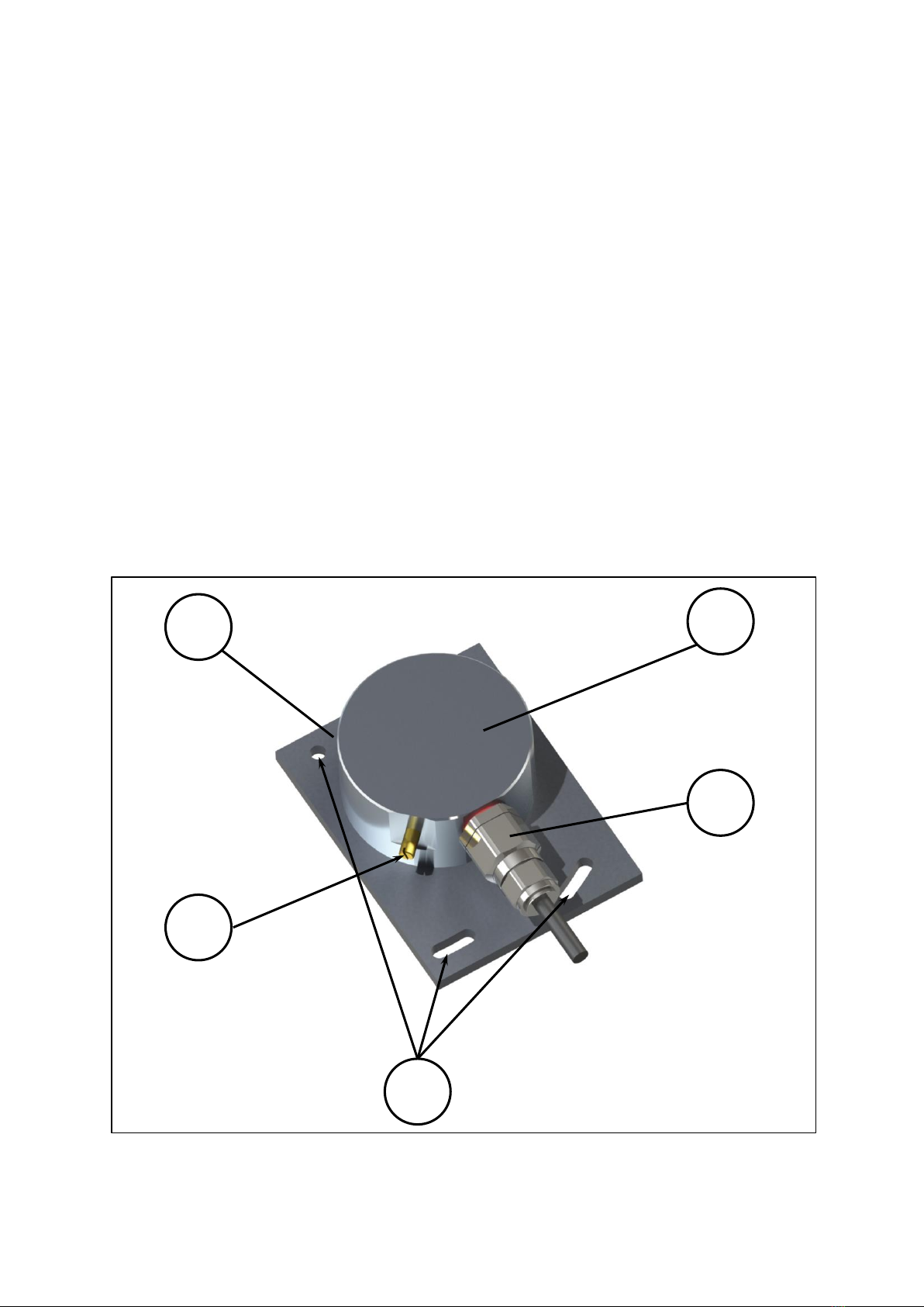
c) Installation of the sensor into the measuring point: The angle sensor is to be attached to
the device using the facilities available on the base plate (drilled holes, slots etc.) and
appropriate securing elements.
After the attachment, the angle sensor is to be aligned in accordance with the label and
then fixed in place. Attention must be paid to the correct alignment of the angle sensor
(see label, see Section 1.3.)
WARNING! The angle sensor must not be aligned using impact tools!
WARNING! A misaligned sensor leads to erroneous measurement results!
d) Making the electrical connection: The electrical connection elements present on the sen-
sor, if necessary including the earthing connection, are to be connected to the power
supply and the evaluation system of the device. In doing so, the information given on the