Broseley INSETO 50 User manual

© 2007-2008 Broseley Fires Ltd
INSTALLATION AND OPERATION
INSTRUCTIONS FOR WOODBURNING:
Tested to EN 13229
This appliance must be installed and commissioned by a fully qualified, registered engineer. THESE
APPLIANCES ARE DESIGNED TO BURN WOOD ONLY
A “Declaration of Completion” Certificate must be obtained for the installation and retained by the end user.
Failure to comply with these requirements may void the warranty.
PLEASE READ THESE INSTRUCTIONS THOROUGHLY BEFORE INSTALLING, OPERATING OR SERVICING THIS APPLIANCE.
ISSUE-09-C

© 2007-2008 Broseley Fires Ltd 2
PLEASE READ THESE INSTRUCTIONS THOROUGHLY BEFORE INSTALLING,
OPERATING OR SERVICING THIS APPLIANCE.
Congratulations on buying a product distributed by Broseley Fires Ltd.
INTRODUCTION
Please read the following instructions carefully to get the best from your new purchase.
The keys to safe, successful and efficient wood burning are good planning, correct installation (by a qualified
heating engineer) and proper operation.
Modern homes have better levels of insulation and are more energy efficient, with more effective and better seals
on doors and windows. This makes our homes easier to heat, but also means that solid fuel appliances must be
more carefully designed so that they will function correctly in the energy efficient, modern homes of today. The
more energy efficient a house is, the less fuel is required to heat it. Less fuel use means less impact on the
environment.
The operation of our appliances, so that they do not produce excessive smoke (beyond the initial light up and
reloading periods) is most important. When our appliances are not smoking, it is an indication that they are being
operated correctly and are burning efficiently. The escape of any unburnt particles and some gases into the
atmosphere are the cause of air pollution.
Our appliances are designed to ensure that the combustion of all gases and particles takes place within the
firebox, to maximise the heat output of the appliance and to minimize the discharge of particulate emissions to the
atmosphere.
It is important therefore, for appliances to be operated in accordance with our instructions in a manner that
maintains a high temperature in the firebox with an adequate supply of air to ensure efficient combustion. A good
indication of efficient combustion is a bright lively flame in the firebox. A dull flame or smoldering fire indicates
poor or incomplete combustion.
To maintain adequate heat in the firebox, it is very important to use dry, well seasoned wood with less than 20%
moisture content. The wood must be correctly sized for the particular appliance and it also helps to have at least
three or four pieces burning at the one time to assist the combustion process.
Adding single pieces of unseasoned or wet wood to a fire will reduce the firebox temperature and prevent
adequate combustion. This will result in increased smoke emissions causing the flue and internal components of
the appliance to become blocked with tar and creosote more quickly. The tar and creosote deposits in the
chimney will fuel a chimney fire.
Please note that it is a requirement under the Broseley Fires Ltd’s warranty system that the
installation of the stove is carried out under by a Competent Person registered with a
Government approved Competent Persons Scheme. HETAS Ltd operate such a Scheme and a
listing of their Registered Competent Persons can be found on their website at
www.hetas.co.uk.
A “Declaration of Completion” Certificate must be obtained for the installation and retained by the end user.
Failure to comply with these requirements may void the warranty.
PLEASE READ THESE INSTRUCTIONS THOROUGHLY BEFORE INSTALLING,
OPERATING OR SERVICING THIS APPLIANCE.

© 2007-2008 Broseley Fires Ltd 3
INDEX
1. TECHNICAL DATA
2. GENERAL DECLARATION
3. KEY ENVIRONMENTAL CONSIDERATIONS
4. TECHNICAL DESCRIPTION
5 THE ‘AIR’ CONTROLS
5A. THE PRIMARY AIR CONTROL
5B. SECONDARY AIR CONTROL
7. FUEL OPTIONS
7A BURNING WOOD
8. INITIAL BURNING & CURING OF THE STOVE
9 n/a
10 LIGHTING AND MAINTAINING A LOG FIRE
11 ASH REMOVAL – CLEANING OUT THE ASH
12 WOOD ASH DISPOSAL
13 n/a
14 OPERATING IN TRANSITION PERIODS (Summer)
15 STANDARD VENTILATOR OPERATION
15 A DEFLECTOR OPERATION
16 CLEANING AND MAINTAINING THE APPLIANCE
16 A DAILY CARE
16 B CAST IRON
16 C GLASS CLEANING
16 D BROKEN GLASS
16 E ASH REMOVAL
16 F FLUE MAINTENANCE
16 G ROPE SEALS
16 H SOAPSTONE
16 I AIR CONTROLS
17 SPARES
18 CHIMNEY FIRE
20 INSTALLATION OF THE APPLIANCE
21 FLUE REQUIREMENTS
22 FLUE AND CHIMNEY GUIDANCE
22 A LINING THE FLUE
22 B FLUE TERMINATIONS
22 C PROVISION OF A NOTICE PLATE
23 SITING THE APPLIANCE
23 A HEARTH REQUIREMENTS
23 B STOVE CLEARANCES
24 VENTING THE HOUSING
25 ADDITIONAL VENTILATION
26 ADDITIONAL WARM AIR VENTS
27 ISOLATING PLUG POSITION
APPENDIX A TECHNICAL DRAWINGS OF THE APPLIANCES
APPENDIX B TECHNICAL DRAWINGS OF THE OPTIONAL ‘DELUXE’ VENTILATION KIT
ANNUAL SERVICE RECORD
LIMITED WARRANTY

© 2007-2008 Broseley Fires Ltd 4
1. TECHNICAL DATA
PLEASE REFER TO ATTACHED TECHNICAL DRAWING FOR OTHER DIMENSIONS NOT LISTED HERE
INSERTO 50 INSERTO 80 INSERTO 100
Nominal heat output (kW) 6 9 9.5
Efficiency (%) >78 >78 >78
Flue diameter MINIMUM
*an adaptor is required 125mm
(5”) 150 mm
(6”) 150 mm
(6”)
Maximum log length (cm) 30 60 80
Hourly WOOD consumption (Kg/h)
(to maintain nominal output) 1.8 2.8 2.9
Flue draft Pressure (Pa) (H20)
(tested when hot) 12
(1.2mm water) 12
(1.2mm water) 12
(1.2mm water)
STANDARD Ventilation kit fitted fitted fitted
DELUXE Ventilation kit
(fits under body of appliance) Not available
OPTION
AVAILABLE
OPTION
AVAILABLE
Type of grate Flat grate Flat grate Flat grate
Ceramic glass door yes yes yes
Removable ash drawer yes yes yes
Adjustable primary air yes yes yes
Adjustable secondary air yes yes yes
Certification CE DIN EN13229 DIN EN13229 DIN EN13229
Approximate weight (Kg) 95 130 160
External dimensions (mm)
Width
Height
Depth
500
555
500
960
555
500
1000
555
500
* Please refer to the chapter on flue requirements, chapter 16.
2. GENERAL DECLARATION
Subject: Asbestos and cadmium
It is declared that all our products are assembled with materials that do not contain any asbestos or its derivatives
and that the materials used for welding do not contain cadmium in any form.
Subject: Regulation CE no. 1935/2004
It is declared that in all our products the materials that are destined to come into contact with foodstuffs are
adapted to food use in line with the above regulation.
Our responsibility is limited to the appliance. It is the responsibility of the purchaser to ensure that the installation
is carried out in accordance with building regulations.
We are not liable for any product modified without authorisation nor if any non original spare parts are used.
3. KEY ENVIRONMENTAL CONSIDERATIONS
To minimize the impact on the environment the following issues need to be considered when proposing to install
and operate a solid fuel appliance:
•Local authorities (Councils) must be consulted for any restrictions that may apply to the use of solid fuel
appliances in certain areas such as smoke free zones.
•The appliance must be correctly sized to suit the space and necessary clearances must be strictly
adhered to.
•The appliance and flue system must be correctly installed to the current regulations in force at the time.
•The appliance must be correctly operated.
•The appliance and flue system must be properly maintained.
•It is also important to ensure that the dwelling to be heated is well insulated and is as energy efficient as
is practical before a heating appliance is chosen and installed.
•The correct fuel must be used.

© 2007-2008 Broseley Fires Ltd 5
4. TECHNICAL DESCRIPTION
These appliances have been developed to burn wood at a very efficient rate. The figures quoted here are from
test firings using beech logs with a moisture content of less than 20%.
The appliance is engineered using the latest manufacturing techniques and modern computerized machinery.
On some of the appliances there is a surround option. These are in various finishes including Italian ceramic tiles
and genuine soapstone finish. Soapstone is a soft-textured stone that possesses fantastic heat-retaining
properties. The absorbent stone holds heat extremely well. Even after the fire has gone out, warmth radiates from
all stone surfaces, ensuring an even, long-lasting heat supply. Another finish that’s available is a glass finish that
gives the appliance a modern contemporary look.
5 THE ‘AIR’ CONTROLS
The stove is fitted with two manual air controls that adjust the flow of air into the unit. It is very important that
these controls are fully understood in order to achieve the best results from your stove.
When operating the controls, ensure that they are used in small increments and not changed by large amounts
suddenly. Do not use them like an on – off switch.
It is important that the controls are used correctly.
The air controls are as follows:
•PRIMARY AIR CONTROL
•SECONDARY AIR CONTROL (AIR WASH)
There is a control for the ‘standard’ ventilator fans. See chapter 15 for details.
5 A THE PRIMARY AIR CONTROL see FIG.1. 1 A + 2A
The primary air control is found on the front of the appliance, just below the glass door on the left hand side; it is
in the style of a pull-push lever. This allows air to enter from below the grate across the ash drawer. To open the
control pull the lever towards you, to close it push it in. This control is used mainly when lighting the fire.
The ash drawer and chamber must be regularly emptied, so that the ash does not obstruct the entry of primary
air.
5 B SECONDARY AIR CONTROL (pull-push lever) See FIG.1. 2A
The ‘secondary air control’ is also in the style of a pull-push lever. This is found on the front of the appliance, just
below the main loading door on the right hand side.
Combustion air entering the stove through this vent will be directed down the inside of the glass panel, this is
known as the ‘air wash system’. The air helps to keep sooty deposits from sticking to the glass and obscuring the
view of the flames. Having clean glass also improves the heat radiation through it.
This control will be used when the fire is fully established. When the lever is pushed in it is open, to close, pull it
out.
FIG. 1

© 2007-2008 Broseley Fires Ltd 6
6 USING YOUR STOVE – IMPORTANT NOTES
This appliance must be installed and commissioned by a fully qualified, registered engineer. HETAS engineers
are recommended by Broseley Fires. For your nearest search www.hetas.co.uk
THE SURFACES OF THIS APPLIANCE GET HOT WHEN IN USE. PLEASE ENSURE THAT CHILDREN, THE ELDERLY
AND THE INFIRM ARE MADE AWARE OF THIS
•Serious damage can result if the appliance is left running with the air controls fully open for extended periods.
•Make sure that none of the doors are left open while the appliance is in operation.
•Never leave the appliance unattended during the initial lighting sequence.
•Do not attempt to open the door immediately after igniting the fire. This could cause a flame flash out.
•Always wear the protective gloves when operating the appliance controls.
•Never burn enhanced fuels such as ‘Petrocoke’
•Do not overload the appliance with fuel.
•Never use flammable chemicals or fluids, such as gasoline, to light a fire.
•Using the appliance on a very low output will cause excessive amounts of tar to build up inside the flue and
can be a serious fire risk, as this will fuel a chimney fire.
•If you regularly run the appliance at a very low output, you will need to have the flue cleaned more regularly.
•Never overload the stove (consult the technical table- maximum allowable quantities)
•We advise that you have the appliance serviced annually by a competent heating engineer before the
beginning of a new heating season.
•Do not cover the permanent air vent that your heating engineer has installed; this is necessary for the correct
combustion of the appliance and your safety.
7 FUEL OPTIONS
These appliances have been developed to burn wood. The results quoted in our literature are from test firings
using beech logs with a moisture content of less than 20%. Coal should never be burnt in these appliances
7 A BURNING WOOD
Hardwoods have a far greater calorific value than softwoods, weight for weight. Any wood needs to be stored in a
well ventilated shelter to season it. Wood used in this appliance must have a moisture content of less than 20%.
Damp or wet wood will quickly form tar deposits on all the internal areas where the combustible gasses travel,
preventing the efficient release of heat from the appliance. The inside of the chimney/flue will also be coated,
there is a greater risk of a chimney fire occurring.
When selecting wood, also take into consideration ease of splitting, ease of ignition and burning, how much
smoke it produces and its "coaling" qualities. "Coaling" refers to the ability of a species of wood to form a long-
lasting bed of hot coals when burned. Coaling qualities improve with wood of a higher density. Wood is not a long
burning fuel and so it is not always possible to keep the stove in overnight. SEE BELOW (maintaining a wood fire)
8 INITIAL BURNING AND CURING OF THE APPLIANCE
The first time that the appliance is lit, there will be an odour given off. This is the components of the appliance
curing. It will be necessary to ventilate the room in which the appliance is sited.
The first firing needs to be done carefully to allow all of the components of the appliance to settle gradually. Never
try to run the appliance flat out the first time you light it. It will be necessary to keep the fire burning for longer
periods rather than short periods the first four to five times. This will be the best way to achieve correct settling of
the appliance. Do not burn the appliance at an accelerated rate; a steady burn is all that is required.
Gradually build up the output of the fire so that no sudden stresses are put on the components of the appliance.
During the first lightings, nothing should be leant against the stove and in particular on the varnished
surfaces. The varnished surfaces must not be touched during the initial curing process.

© 2007-2008 Broseley Fires Ltd 7
10 LIGHTING AND MAINTAINING A LOG FIRE
•Use scrunched up paper and dry kindling to start the fire. An alternative is to use fire lighters.
•Open the primary and secondary air controls to the fully open position. It will take a short time for the fire
to establish itself.
•When the fire is burning hot, add small pieces of very dry wood, preferably hardwood as these generate
better embers.
•Keep all the draft controls fully open till a bed of hot, glowing embers is established.
•Once you have some red hot burning embers, open the door and rake the embers evenly over the grate
before adding larger pieces of wood.
•We suggest that you do not fully load the appliance until you have become completely familiar with the
operation of ALL the controls.
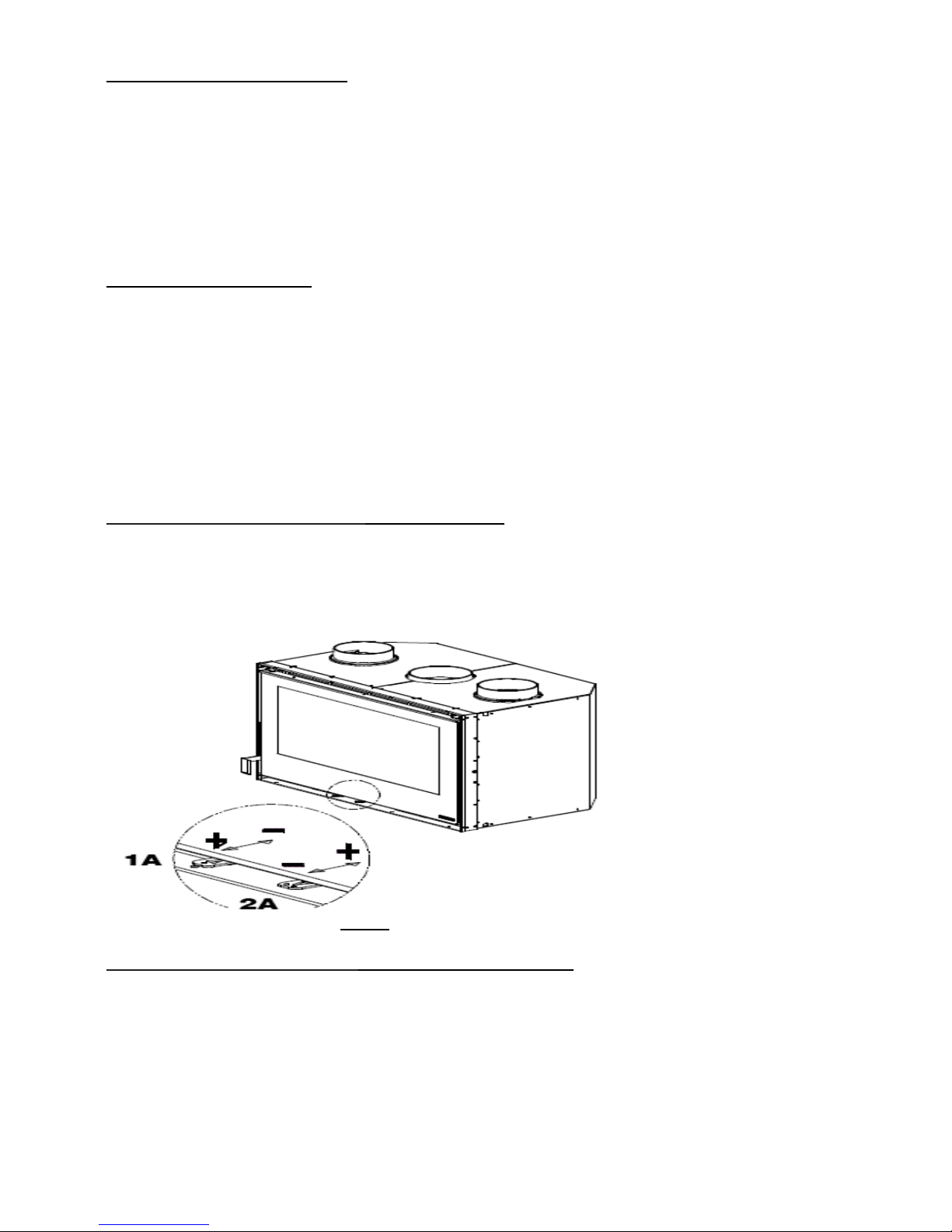
•For best results, open the secondary air control and close the primary air control. The output of the
appliance can now be controlled using the secondary air control. This is when burning LOGS.
•Do not open the loading door too quickly when reloading the appliance, as this can cause fumes to flash
out the door.
•A typical load will be 2 KG; this will maintain the output of this appliance
•Do not burn painted or varnished woods, MDF, oak bark or any wood with more than 20% humidity.
•It is not necessary to riddle the ash using the ‘riddling grate’ as wood burns best on a flat surface.
•
11 ASH REMOVAL – CLEANING OUT THE ASH
The removal of the ashes should be done when the appliance is cold.
When you burn logs, you will be left with ashes. They must be removed periodically for the correct and efficient
operation of your appliance.
Don’t wait till the ash pan's completely full. The frequency of this ash removal will depend on the type of fuel being
burned, i.e. Softwood & hardwood; all create differing amounts of ash.
Keep in mind that cleaning your appliance boosts its efficiency, as ash, soot or tar deposits will block the heat
from coming out of the appliance.
Excess ash in the pan will cause a coal fire to go out and may cause severe damage to the grate. It may also
prevent the ash door from being shut correctly.
Take care when removing the ash, as small bits of hot embers can stay dormant for long periods when buried in
ashes. These will then flare up again when exposed to oxygen. Use a metal container to carry any ash.
For your own protection, a pair of heat proof gloves and a dust mask may be necessary.
12 WOOD ASH DISPOSAL
The best thing to do with your ashes is to put them in your garden. Wood ashes are high in potassium, calcium,
sodium, magnesium, and phosphorus.
Wood ash will make your soil more alkaline, so apply it appropriately for your soil.
If you have no garden, you can dispose of completely cold ash with your household trash.
Place it in a tightly closed bag to keep it contained. Use the same precautions as disposing of coal ash.
14 OPERATING IN TRANSITION PERIODS (Summer)
When the outside temperature gets to be more than the temperature within the property, there is a strong
possibility of the flue working in reverse. If the appliance is not lit, this will cause the draught of the flue to travel in
a downward direction and the smell of smoke will be obvious in the room.
If you experience problems lighting the appliance because of the greater outside temperature, then it will be
necessary to warm the flue before loading the appliance with kindling. There are various methods for this
procedure. Ask your local supplier or registered chimney sweep for advice.
If the fire is lit, the heat output of the appliance is often reduced and the exhaust gases may not come out the
chimney completely. This can cause them to come back into the room. In this case:
•shake the embers more frequently,
•increase the air for combustion and
•only load a reduced quantity of fuel.
This will help to keep the chimney hot and working efficiently.
Check that all the seals of the appliance are in good order and that the connections to the chimney are also
sound.

© 2007-2008 Broseley Fires Ltd 8
15 STANDARD VENTILATOR OPERATION
The appliance comes with a pair of fans just below the main door. This is where the air is drawn in, not where it is
blown out. After you have lit the appliance, the hot air that is generated; between the inner and outer casing; can
be vented either out of the front vent on the appliance (above the door) or up the ‘additional warm air vents’, The
Inserto 50 does not have additional air vents. see chapter 26.
The standard ventilator has three speeds. OFF – LOW – HIGH.
FIG. 2 shows the three position slider switch.
FIG. 2
15 A DEFLECTOR OPERATION
To divert the hot air either up the vents or into the room, there is a deflector that needs to be operated. Please see
FIG. 4 A and 4 B to see the position of this item. Use the supplied operating tool to position the deflector either
vertically, to distribute the hot air up the ventilation tubes; or horizontally, to have the hot air exiting the appliance
from the vent above the door.
FIG. 4 A FIG. 4 B
16 CLEANING AND MAINTAINING THE APPLIANCE
The appliances have three main surface finishes; these should be cleaned when the appliance is cool. Please
follow any instructions to the letter for any special cleaning agent that you may use. Ash removal and chimney
maintenance are also important areas to be aware of to ensure the efficient and correct operation of your
appliance. Please read on….
Take great care choosing the products you use to clean your appliance. A major amount of cleaning can be
carried out using hot soapy water and a soft cloth. Using the wrong products will cause damage to its surfaces.
Never use bleach or chlorine based products, caustic cleaners, paint solvents, biological powders, coarse
abrasives or salt.
Never mix different products as they may cause a chemical reaction with each other and cause harm to either you
or the appliance. Read below to see specific cleaning techniques.
For the more stubborn stains, a mildly abrasive cleaner should be used, such as ‘Astonish’.
This is safe to use on enamel surfaces. Do not use Astonish on the chrome components.
For any further information, please contact your Dealer!
16 A DAILY CARE
To keep the surfaces of your appliance bright and clean, a daily wipe over with a lint free cloth is all that is
needed. A wet cloth may be used on certain surfaces. Try not to use excessive amounts of water when cleaning
the appliance. To buff the cleaned surfaces, a soft, dry, lint free cloth should be used.
16 B CAST IRON
This can be cleaned with a lint free, damp cloth. Do not leave this surface wet. If it is cleaned when the appliance
is slightly warm, the damp surface will dry by itself. Otherwise, wipe the surface dry after cleaning. Another
OFF
LOW
HIGH
INSERT TOOL INTO SLOT
AND LIFT FLAP.
(this diverts hot air up vent tubes)
DEFLECTOR
OPERATING
TOOL

© 2007-2008 Broseley Fires Ltd 9
method is to brush the surface with a soft brush. This is good for cleaning in the more detailed and difficult to get
to areas. If cast iron is left for long periods in a damp atmosphere; such as a fireplace; it may start to show signs
of rust. To prevent this, wipe the surface over with light oil. This will burn off when the fire is re-lit.
16 C GLASS CLEANING:
Only clean the glass when the appliance is cold. There are various glass cleaners you can buy at stove shops
that are specially designed to remove hydrocarbon (soot) and fly ash (mineral) deposits from the glass. Follow the
manufacturer’s instructions. Typically, just spray a small amount of cleaner on the glass and use a paper towel or
rag to wipe it clean. Alternatively use a proprietary ceramic hob cleaner such as Hob-brite, as used for ceramic
hobs. Follow the directions on the product. The directions for use on the bottle are to turn the appliance off, apply
cleaner with paper towel or clean cloth, rub the glass lightly, rinse residue and dry the glass with a paper
towel/soft clean tissue.
If you only burn logs in your appliance, then you can dip a damp cloth in the ash and use this to scrub the glass
clean. Do NOT use this method if you use coal, as the ash produced is too abrasive.
16 D BROKEN GLASS
The glass in the fire door is ceramic and is resistant to sudden temperature changes up to 750 degrees
Centigrade. Breakage can only be caused by mechanical shock (collision, violent damage etc) because of this,
replacement is not covered by the guarantee.
16 E ASH REMOVAL:
The efficient operation of your appliance is dependant on its correct installation, operation and maintenance.
Leaving soot to accumulate inside your appliance will drastically reduce the output of the appliance and prevent it
from doing what it is designed to. Ensure that the ash inside every part of the appliance is removed, not just the
ash pan. Ash will settle on top of the baffle and this is an area that will also need periodic inspection.
16 F FLUE MAINTENANCE:
Call a certified chimney sweep (National Association of Chimney Sweeps) or other qualified professional to clean
the flue system. These professionals have the equipment and the experience to do a thorough job. The sweep will
advise you as to the intervals that you should have your flue swept. We would recommend that you have it swept
at least twice a year, but you may need to sweep it more.
Get them to inspect the condition of all the associated chimney items and report to you on their condition.
Since coal residue contains sulfur, the metal flue pipe and chimney systems tend to deteriorate much faster than
when burning wood. Be sure to check the pipe at least once every six months to determine if it has corroded.
16 G ROPE SEALS:
For the appliance to operate correctly, it is important that all the seals; where fitted; are in good condition and are
sealing correctly. They should be replaced if they are showing excessive signs of fraying and are not making a
good seal. They are glued into position using a high temperature, flexible, silicone sealant
16 H SOAPSTONE
Allow the soapstone to cool to room temperature on its own before cleaning. Rinsing with a sponge and hot water
is usually sufficient to clean soapstone.
16 I AIR CONTROLS:
Ensure that all the air controls operate smoothly and are free from ash or other foreign bodies. Pay particular
attention to the damper flap at the rear of the ash drawer. Clean this area with care and ensure that excessive
amounts of ash are kept from building up and affecting the operation of this control.
17 SPARES
THE APPARATUS MUST NOT BE MODIFIED IN ANY WAY.
ONLY SPARE PARTS EXPRESSLY AUTHORISED OR SOLD BY BROSELEY FIRES LTD. MAY BE USED.
CONSULT YOUR LOCAL AUTHORISED DEALER FOR ADVICE.

© 2007-2008 Broseley Fires Ltd 10
18 CHIMNEY FIRE
If a chimney fire occurs in the flue or the chimney:
1. Immediately shut off the air supply by closing all dampers and air openings on the stove.
2. Ensure the main door and ash door are securely closed.
3. If the fire in the stove or fireplace can be extinguished safely; with a CO2 extinguisher; put it out as
quickly and safely as possible. Do not attempt to put out the fire using water.
4. Close all windows and doors to the room.
5. Call the fire brigade
When the chimney has stopped burning have it checked by a specialist for possible cracks or leaks.
Please review the way you are using the appliance and check that the fuel you are using is suitable. Chimney
fires only occur if the appliance has been wrongly installed, maintained, or operated. Damage caused to an
appliance where a chimney fire has occurred is not covered by any guarantee.
•Please comply with the technical data given in this instruction manual.
•Illegal installations are not covered by any sort of guarantee.

© 2007-2008 Broseley Fires Ltd 11
20. INSTALLATION OF THE APPLIANCE
THIS APPLIANCE MUST BE INSTALLED AND COMMISSIONED BY A FULLY QUALIFIED, REGISTERED ENGINEER.
The guarantee is void if any part of the installation is found to be illegal.
Because of nature of this type of appliance, it is not possible to give step by step fitting instructions for the
appliance. Please read the following advice before starting any work and make the necessary pre-installation
checks.
21 FLUE REQUIREMENTS
This appliance has a European sized flue collar that is metric in size. An adaptor is required for the initial
connection to the flue collar. A standard (imperial sized) adaptor with a crimped leading edge will allow the flue to
fit inside the flue collar of the Inserto 80 & Inserto 100.. Please refer to the diagrams and tables below for further
details.
The technical drawing of the ‘MAIN FLUE COLLAR’ is shown below in FIG. 5
FIG. 5
The diameter of the ‘ADDITIONAL WARM AIR VENTS’ is shown below in FIG. 6 (below)
FIG. 6
MAIN FLUE COLLAR
FIG. 7 STOVE PIPE CONNECTIONS
INSERTO ØA ØB ØC
50 130 122 118
80 160 151 148
100 160 151 148
INSERTO ØA ØB ØC
50 OPTION NOT AVAILABLE
80 150 -- 140
100 150 -- 140

© 2007-2008 Broseley Fires Ltd 12
22 FLUE AND CHIMNEY GUIDANCE
•This appliance must be installed into a ‘Class 1 Chimney’. If there is no existing chimney, then an approved
solid fuel, factory built, prefabricated block type or a twin walled, stainless steel flue can be used. Get advice
from a qualified chimney engineer. Flue sharing is not allowed.
•The minimum flue diameter for Inserto 80 & 100 must be Ø150mm and Ø125mm for the INSERTO 50.
•If excessive draw is present, then a suitable ‘flue draught stabilizer’ should be fitted. See data table.
•If the chimney suffers from down draught, then a special ‘anti-downdraught’ cowl will need to be fitted. In
exposed windy locations, a ‘stabilizing’ cowl may need to be fitted. The minimum cowl requirement that we
recommend, is a rain cowl with a bird guard.
•To perform satisfactorily, the chimney height must not be less than 5 meters from stove to cowl. If there are any
bends in the flue, this minimum length will need to be increased by 1 meter for each bend.
•The initial connection to the appliance will need to be 600mm vertical before any bend.
•A maximum of four 45 degree bends is allowed in any complete flue; from stove to cowl.
•Adequate access for sweeping the flue, such as a soot door, must be provided.
•Flue pipe should be fitted inside the flue pipe collar (spigot) to prevent creosote and condensates from running
down onto the top of the appliance. (see specifications for exact collar sizes)
•All flue pipe must be suitable for solid fuel (complies with latest European regs.) and fitted in accordance with
building regulations, whilst complying with current legislation and manufacturers’ instructions.
•If a rear flue is able to be fitted, the horizontal length must be no longer than 150mm.
•Mechanical ventilation in the same room as any solid fuel appliance must be avoided.
Further instruction on the installation of the ‘additional warm air vents’ can be found in chapter 22.
These allow the warm air to be piped into the room in which the appliance is sited. With the installation of the
deluxe ventilator kit; which comprises of a more powerful fan; the warm air can be vented further down the
additional warm air vents.
The natural up-draft on a chimney will depend on a number of factors. The chimney is one of the most important
parts of the installation; great care should be given to its design.
The draw of the chimney should be at least 12 Pa (1.2mm of a column of water). The measurement must always
be done when the stove is hot (producing nominal heat values). When the pressure exceeds 17 Pa (1.7mm of a
column of water) it will be necessary for the installation of a flue draft stabilizer. The flue draft measurement is
critical and MUST be measured. If incorrect, the appliance will NOT operate correctly and damage may occur.
22 A LINING THE FLUE
An independently certified flexible metal liner can be used to reline a chimney. A chimney liner should be installed
in accordance with Building Regulations Part J, reference should also be made to the manufacturers instructions.
An insulated chimney is the most efficient and safe way to burn wood and coal. Tar deposits condense in a cool
chimney. An insulated chimney helps prevent these deposits. A standard, unlined chimney will gradually get
saturated in tar, this is a fire hazard. Tar stains may appear on the surface of the chimney breast inside the
property.
22 B FLUE TERMINATION
The height and termination of the flue is an
important part of the installation and consideration
needs to be made to ensure that the flue is high
enough to create sufficient draft to clear the
products of combustion. The termination of the
flue outlet position which can meet the
requirements in common circumstances are
shown in Document J. If there are unusual
circumstances that will affect the efficient and safe
removal of the products of combustion; the height
and/or the separation distances shown in
Document J may need to be increased and a
special cowl may need to be fitted to help correct
the issue.
FIG. 8
Wind induced downdraft
from nearby tall trees
WIND DIRECTION

© 2007-2008 Broseley Fires Ltd 13
22 C PROVISION OF A NOTICE PLATE
A notice plate must be durable and be fixed on site, where a hearth, fireplace flue or chimney is provided or
extended (including cases where a flue is provided as part of refurbishment work). ADJ states that the
responsibility for achieving compliance with the requirements of Part J rests with the person carrying out the work
and so this person must be competent in the work they are being asked to do. The completed flue must pass the
appropriate tests that assess whether the flue in the chimney, the connecting flue pipe (and flue gas passages in
the appliance) are free of obstruction and acceptably gas tight. In addition, appliance performance tests, including
flue spillage tests should be carried out when an appliance is commissioned.
23 SITING THE APPLIANCE
This appliance must not be fitted into a location where it will be impossible to service. The location must comply
with the requirements laid down in the Building Regulations. Minimum clearances within these instructions must
be complied with.
23 A HEARTH REQUIREMENTS
The positioning of the appliance and dimensions of the hearth must comply with current national and local
building regulations and be at least the minimum sizes shown in the diagram below See FIG 9.
If the appliance is fitted into a setting that raises it further above the hearth than the minimum dimension shown in
FIG xxx, consideration must be given to the depth of the hearth in front of the appliance. The higher up the wall
that the appliance is located, the deeper the hearth will need to extend in front of the appliance. This will hopefully
prevent any combustible materials from falling outside the perimeter of the extended hearth.
23 B STOVE CLEARANCES
X = DISTANCE OF APPLIANCE ABOVE SURFACE OF NON COMBUSTIBLE HEARTH.
STOVE CLEARANCES TO NON - FLAMMABLE MATERIALS
B = X + 300mm (up to a maximum of 900mm)
C = X + 200mm (up to a maximum of 400mm)
STOVE CLEARANCES TO FLAMMABLE MATERIALS
•The minimum distance from any flammable object, or one that is sensitive to heat, (furniture, wood, fabrics. etc.)
and from materials with flammable structure, must be 200 mm to the rear and 200 mm both sides.
•In front of the appliance there must no flammable object or building material sensitive to heat within 1000mm.
•Above the appliance, there must not be any flammable items within 630mm.
CONSTRUCTIONAL
HEARTH
DECORATIVE
HEARTH
FIG. 9

© 2007-2008 Broseley Fires Ltd 14
24 VENTING THE HOUSING
To allow an air loop inside the appliances location, it is necessary to have an air entrance vent hole (position A)
below the appliance and another vent above the appliance. (position B)
The intake vent (A) air can be drawn in from the room in which the appliance is installed, or directly from outside.
Obviously, air directly from outside will tend to be cooler.
To ensure the correct and safe operation of the appliance, when building the housing in which the appliance will
be located, it is necessary to respect the clearances between the insert and the inner walls of the housing.
Considering the measurements given in the technical specifications, you need to account for at least 60 mm of air
space above, behind and on the two sides of the appliance.
It is critical that the chamber in which the appliance is located is well ventilated with ENTRY & EXIT vents.
There is a requirement for a 60mm gap down each side, behind and above the appliance. This will allow
the chamber to breath and prevent the build-up of hot air that could cause damage to the housing.
FIG. 10 A
CLOSE-UP VIEW OF
5mm GAP
FIG. 10
The gap generated between the top edge of the appliance and the housing will be less.
The minimum recommended distance here is 5mm.
The void behind the appliance, down each side and above it will be 60mm, as shown in the diagram above.
EXIT VENT
(POSITION B)
MINIMUM
CLEARANCE
60mm
ENTRY VENT
(POSITION A)
5mm
(Front edge only)
5mm

© 2007-2008 Broseley Fires Ltd 15
25 ADDITIONAL fixed VENTILATION (to aid combustion)
There must be sufficient free air for combustion into the room where the appliance of 5Kw or more is installed.
THIS IS A LEGAL REQUIREMENT.
Permanent openings or vents must not be covered. Vents needs to be positioned carefully, they must be
protected from direct wind conditions. A baffle that has been specially designed to fit over the vent will protect it
from the effects of wind, but must not restrict the total vent area and must be secured in a way that prevents its
movement. Regular inspection of any vents is critical to ensure that the vent has not become restricted.
The appliance may require up to 40 m3/hour of combustion air. The natural recirculation of air must be guaranteed
by having permanent ventilation to the outside.
An extractor fan, cooker hood or similar product, installed in the same room, or in a room nearby; that sucks air
out (aspirating); may negatively affect the functions of your appliance.
If the room contains more than one appliance; of the type that requires combustible air; a calculation will need to
be made to re-calculate the permanent air vent requirement.
Please see the ‘Technical Data’ list at the front of these instructions or refer to current building regulations for
fixed additional ventilation requirements.
26 ADDITIONAL WARM AIR VENTS
The Inserto 80 and 100 models have additional features. They are equipped with a fan to improve the flow of the
convected heat from around the body of the stove into the room. ‘ADDITIONAL WARM AIR VENTS’ may be
added to the appliance to allow the venting of warm air to a maximum pipe length of 1.5 meters; when using the
‘STANDARD’ ventilator; and 4 meters when the ‘DELUXE’ ventilator has been fitted. The Deluxe ventilator can be
purchased as an additional item. When switched on, a variable thermostat will adjust the temperature at which the
fans come into operation. This should be installed by a qualified electrician and compliance with current
regulations must be observed. Or the fan can simply be switched on when desired.
A further feature of these models is the provision of further vents if required via two blanked outlets on the top of
the body of the stove see Figure 4, below.
The vents should be connected to the body of the stove using fire resistant pipe of ø150mm. The blanks on the
top of the stove will need to be removed and the collars provided should be screwed into place to enable the
hoses to be securely clamped in place.
Each pipe should not exceed 1.5m in length unless forced ventilation; the ‘DELUXE VENTILATOR’ is used; in
which case they can be up to 4m long. If this is required, the optional ‘deluxe’ ventilation kit should be fitted. For
details see the technical drawings below. (see appendix B)
27 ISOLATING PLUG POSITION (For the ‘standard’ fan)
The picture to the left shows the isolating plug that has a possibility
of two positions. It is found on the printed circuit board inside the
control box of the ‘standard’ ventilator kit. If the appliance being
installed is the MODEL 50, then the plug needs to be fitted onto
the two left hand pegs.
The picture here shows the plug on the two right hand pegs, this is
suitable for the MODEL 80 and the MODEL 100.
FIG. 11
ADDITIONAL
WARM AIR
VENTS

© 2007-2008 Broseley Fires Ltd 16
FIG. 12
APPENDIX A TECHNICAL DRAWINGS OF THE APPLIANCES
INSERTO 50
INSERTO 80

© 2007-2008 Broseley Fires Ltd 17
INSERTO 100

© 2007-2008 Broseley Fires Ltd 18
APPENDIX B OPTIONAL ‘DELUXE’ VENTILATION KIT
Please allow sufficient clearance below the fan for maintenance.
INSERTO 80 INSERTO 100
A 300 400
B 25 100
C 190 215
ALL DIMENSIONS IN mm. Please refer to the drawing above. (Appendix B)

© 2007-2008 Broseley Fires Ltd 19
ANNUAL SERVICE RECORD
A “Declaration of Completion” Certificate must be obtained for the installation and retained by the end user.
Failure to comply with these requirements may void the warranty.
INSTALLATION DATE OF APPLIANCE:
HETAS ENGINEER: . REG. No.
COMPANY NAME: .
COMPANY ADDRESS: .
POSTCODE:
CONTACT NUMBER
1ST YEAR SERVICE completion date:
HETAS ENGINEER: . REG. No.
COMPANY NAME: .
COMPANY ADDRESS: .
POSTCODE:
CONTACT NUMBER
2ND YEAR SERVICE completion date:
SERVICE ENGINEER: . . REG. No.
COMPANY NAME: .
COMPANY ADDRESS: .
POSTCODE:
3RD YEAR SERVICE completion date:
SERVICE ENGINEER: . . REG. No.
COMPANY NAME: .
COMPANY ADDRESS: .
POSTCODE:
4TH YEAR SERVICE completion date:
SERVICE ENGINEER: . . REG. No.
COMPANY NAME: .
COMPANY ADDRESS: .
POSTCODE:
5TH YEAR SERVICE completion date:
SERVICE ENGINEER: . . REG. No.
COMPANY NAME: .
COMPANY ADDRESS: .
POSTCODE:
6TH YEAR SERVICE completion date:
SERVICE ENGINEER: . . REG. No.
COMPANY NAME: .
COMPANY ADDRESS: .
POSTCODE:

© 2007-2008 Broseley Fires Ltd 20
LIMITED WARRANTY
A “Declaration of Completion” Certificate must be obtained for the installation and retained by the
end user. Failure to comply with these requirements may void the warranty.
You, as the end user, have a contract by law with the supplier / dealer from whom you purchased the product.
That dealer then has the same contract with the manufacturer or wholesaler and these have a contract with their
suppliers.
ALL CLAIMS MUST FOLLOW THIS PROCEDURE.
Thank you for choosing a Product from Broseley Fires Ltd. This warranty gives you specific legal rights.
The statutory rights of the consumer are not affected by the warranty, or the consumers’ rights against the dealer
arising from their sales / purchase contract.
The manufacturers’ warranty:
Your Product will be free from defective parts, material, and workmanship at the time of its original purchase for a
period of one (1) year. This Warranty will become active as of one month from the date of delivery.
This warranty does not cover any failure of the unit due to normal wear and tear, misuse, abuse, accident, illegal
modification, illegal installation or repair, damage resulting from improper use or failure to maintain the product.
Variations in color and texture are a natural characteristic of cast iron products. Colour changes may result from
exposure to light and other elements which are a part of the aging process. These material variations and
changes are not covered by this warranty.
The consumable items within the product are not covered by the warranty, nor is the glass.
If during the warranty period, this Product fails to operate under normal use and service, due to defects in material
and / or workmanship, Broseley Fires will either repair or replace the product.
The repaired or replaced product shall be warranted for the remaining period of the original warranty + the time
taken to days from the date of repair, whichever is longer.
Repair or replacement may involve the use of functionally equivalent reconditioned units. Replaced parts or
components will become the property of Broseley Fires.
Should you wish to claim under the warranty, please contact the supplier / dealer from whom you purchased the
appliance. Do not claim directly to Broseley Fires, as they are unable to process any direct claim from an end
user.
Product design and any specifications are subject to change without notice. This is due to our continuous product
development and improvement. The buyer will not be entitled to request free upgrades to the new design or
compensation for previously purchased products or any products on order.
•This Warranty covers all Broseley Fires costs within the Warranty period.
IN NO EVENT SHALL BROSELEY FIRES BE LIABLE FOR INCIDENTAL OR CONSEQUENTIAL DAMAGES OF ANY NATURE
WHATSOEVER,INCLUDING BUT NOT LIMITED TO LOST PROFITS OR COMMERCIAL LOSS,TO THE FULL EXTENT THOSE
DAMAGES CAN BE DISCLAIMED BY LAW. (if applicable)
NON - COVERAGE OF THE GUARANTEE
If the end-user’s claim should not be covered by this guarantee, the end-user shall be liable for costs incurred by
Broseley Fires such as callout and inspection costs for examination of the product, transportation costs of the
product as well as any other relevant costs.
If, after having been informed about the non-coverage of the guarantee, the end-user wants to have the repairs
done, the end-user shall additionally pay for any spare parts used and for the labour and transportation costs
incurred. If repairs are carried out under this guarantee, the remaining guarantee period for the product shall be
extended by the period of time that has elapsed since the complaint was officially logged with Broseley Fires until
the repairs have been completed
A COPY OF OUR FULL TERMS AND CONDITIONS IS AVAILABLE ON REQUEST.
** End-user means the natural or legal person who owns the product and who has not acquired it with a view to
reselling or installing it in the course of business.
This manual suits for next models
2
Table of contents
Popular Indoor Fireplace manuals by other brands

Pacific energy
Pacific energy Series A operating instructions

Town & Country Fireplaces
Town & Country Fireplaces TCWS.38NG03.C instructions

SEI
SEI LINDA FA8514 Assembly instructions

Montigo
Montigo M38DV-CR Installation & operation manual

Twin-Star International
Twin-Star International 18MM6037 manual

Nordpeis
Nordpeis Napoli installation manual

HWAM
HWAM Autopilot IHS 7100 user manual

Desa
Desa (V)KC42NE SERIE OWNER'S OPERATION AND INSTALLATION MANUAL

Montigo
Montigo B34DV Installation & maintenance manual

Paramount Fitness
Paramount Fitness BLT-999W-3-S Instructions for use

decoflame
decoflame ESPOO CEILING manual

MHSC
MHSC 36STFL Installation and operating instructions