BROWN FireFly FY2x36-45 User manual

FireFly™ & Synergy™
Instructions
Brown Manufacturing Group, Inc.
4661 Staord SW
Wyoming, MI 49548
616-249-0200 fax 616-249-3211
www.brownmfg.net
FY2x36-45 & SY36-84
FireFly Curing System
Synergy Pretreat System
The Synergy™ Industrial Pretreat Module provides complete multi-variate control of
each garment. The system is designed for high volume digital decorators and connects
directly to the FireFly curing system, allowing for rapid evaporation of pretreat solution
and delivery to the digital output device.
$150.00 April 2019
US Patent# 10,011,136

Brown Manufacturing Group, Inc.
4661 Stafford Ave. S.W.
Wyoming, MI 49548
Phone: 616-249-0200
Fax: 616-249-3211
www.brownmfg.net
Conveyor Dryer
Setup Guide

Assembly
A Firefly dryer consists of several modular assemblies
which are joined together to create a complete conveyor
dryer unit. Common modules are:
LOAD DETECT SENSORS
OBJECT DETECT SENSORS
BELT TRACKING KNOBS
BELT ROLLERS
SCANNER HOLDERS
HEIGHT SENSORS
BELT MOTORS
Figure 1: DRIVE ROLLER MODULE
DRONE LOWER
CONTROL CABINET
DRONE UPPER
CONTROL CABINET
FRONT BULB COVERS
TOP AIR FILTERS
CAMERA ACCESS
PLATES
LEVELING FEET
Figure 2: PRIMARY HEAT MODULE
DRONE UPPER
CONTROL CABINET
DRONE LOWER
CONTROL CABINET
CAMERA ACCESS PLATES
TOP FILTERS
LEVELING FEET
Figure 3: DRONE HEAT MODULE
TAKEUP ROLLERS
BELT TRACKING
ADJUSTMENT KNOBS
LEVELING FEET
Figure 4: TAKE UP ROLLER MODULE
CONDENSATION
CATCH PANS
EXHAUST DUCT
STARTING COLLARS
Figure 5: EXHAUST MODULE
Figure 6: COOLER MODULE

Assembly Step 1: Ensure Adequate Clearance:
Before placing the Firefly modules, it is important to
ensure adequate clearance will be available for both the
main footprint of the machine and maintenance access.
Since the Firefly Curing System is a modular system, the
main footprint of the machine depends on the exact
configuration you purchased. Consult your salesperson
for an engineering drawing of your particular system.
Clearance is required around the heat modules in order
to open control panel doors, pull out filters, and clean
camera boxes. See Figure 7 for specific clearance
numbers.
45" CONTROL PANEL
DOOR OPEN CLEARANCE
45" FILTER ACCESS
CLEARANCE
3' CAMERA ACCESS CLEARANCE
(TOP OF MACHINE)
Figure 7: GENERAL CLEARANCES
Clearance is also required for the heat modules to slide
on their tracks for maintenance access to the center of
the machine. Ensure that nothing blocks the movement
of the heat sections front/back as shown in Figure 8.
HEAT SECTIONS
SEPARATE
Figure 8: ACCESSING CENTER OF SYSTEM
Assembly Step 2: Identify and Arrange:
Using the figures in this manual, identify the modules
that shipped with your dryer. Arrange the modules in the
location you wish to install the machine in the correct
orientations for your system. Below is a standard
configuration for a 2 heat section system. As the Firefly
system is a modular system, your configuration may be
different. Consult with Brown Manufacturing for the
exact layout of your system.
Use the leveling legs on each module to bring all the
sections to the same height and level. Shift the modules
as necessary to create a single, straight frame.
DRIVE
ROLLER
MODULE
CONTROL
KIOSK
PRIMARY HEAT
MODULE
DRONE HEAT
MODULE
TAKEUP
ROLLER
MODULE
EXHAUST
MODULE
COOLER
MODULE
TV STAND
(OPTIONAL)
Figure 9: STANDARD MODULE ARRANGEMENT

Assembly Step 3: Connect Modules:
Remove the cover grills from the frames of each section.
Bolt each module to each adjoining module using the
connection holes at the end of each frame.
FRAME
ACCESS
COVER
FRAME
CONNECTOR
HOLES
Figure 10: FRAME CONNECTIONS
Assembly Step 4: Mount Accessories:
Depending on the exact configuration of your system,
you may have to locate and set into position some or all
of the following accessories:
-Load Detect Sensors ()
-Scanners (Mount on scanner stands)
-Height Sensors ()
-TV (mounts on TV stand –Figure 9)
Assembly Step 5: Install Belts:
First, loosen the Belt Tracking Knobs (Figure 11) on
both the front and rear of the machine. Slide the rollers
as far back as they will go.
BELT TRACKING KNOBS
BELT ROLLERS
Figure 11: LOOSENING BELT TENSION
Next, run the belt through the body of the machine. The
belt may have a flap covering the seam. Make sure when
the seam is on the top side of the roller, the attached side
of the flap is on top and moving in the direction of the
belt (Figure 12)
BELT MOVEMENT
DIRECTION
SEAM FLAP
(IF PRESENT)
Figure 12: SEAM FLAP ORIENTATION
Each end of the belt has a row of eyelets. Line up eyelets
together, and push the connector pin through (Figure
13).
CONNECTOR PIN
EYELETS
Figure 13: SEAM CONNECTION

Assembly Step 6: Connect power.
Warning: This equipment is operated by high voltage
electrical power and can be dangerous. Only a
qualified electrician should connect and service this
equipment. Safe and proper installation of this dryer
is the customer’s responsibility.
Note: The wiring of the electrical supply to the dryer
must be in accordance with all local, state, and
national codes.
A main disconnect with overload protection, capable of
switching the dryer’s full pull load must be installed
within reach of the operator.
Each heat section module has an independent power
supply that must have an independent overload current
protection device not exceeding the MAX OCP rating on
the supply information tag on the control panel.
Some modules require two independent power supplies
that must each have an independent overload current
protection device not exceeding the MAX OCP rating
on the supply information tag on the control panel.
Each heat section control panel has a disconnect switch
located inside the panel. Panels with two power supplies
will have two disconnect switches. Wires may enter
through the supplied hole at the bottom of the panel, or
the customer may elect to punch a hole in the sidewall of
the panel. Connect supply power directly to the open
terminals of the disconnect switch, and a ground wire to
the grounding lug located adjacent to the disconnect
switch.
DISCONNECT SWITCH(ES)
INPUT POWER CONNECTS HERE
POWER ACCESS HOLE
GROUNDING LUGS
CONTROL PANEL DOOR
Figure 14: CONTROL PANEL POWER HOOK-UP
Assembly Step 7: Connect control kiosk.
The control kiosk connects to the logic control panel
using three cables – a standard 120V power cable, a
VGA cable, and a USB cable. Connect these wire to any
compatible ports on the main logic control panel.
Assembly Step 8: Venting
Venting of the dryer exhaust air is recommended. The
garments that are cured in this oven will smoke and this
will remove most of the smoke from the printing area.
♦Vent the exhaust air flow to the outside of your
building with standard 10” diameter duct.
♦Long duct runs and changes in duct direction
restricts the air flow. Under certain
circumstances an in-line booster fan may be
required.
♦The exterior end of the duct should be protected
from direct winds that may cause back drafts.
Precautions should be taken to prevent rain
water from entering the duct work.
Assembly Step 9: Wire Machine
The machine has several internal connections between
components that are disconnected for shipping, and must
be reconnected to finish installation. Due to the technical
nature of these connections, it is recommended only a
Brown Technician perform the final wiring operations.

Machine Adjustments
Belt Tension
Apply enough tension to keep the belt from slipping on
the roller. Excessive tension is unnecessary and may
shorten the useful life of the belt.
Belt Tracking
Belt tracking is adjusted with the knobs on the end of the
conveyor frame. Increasing the belt tension on one side
will cause the belt to track towards the opposite side of
the dryer frame. Decreasing the belt tension on one side
will cause the belt to track towards that side. Additional
adjustments my be required when the oven reaches full
temperature or as the belt stretches with wear.
Load and Object Detectors Adjustment and Cleaning
The load sensors and object detection sensors must
work correctly for proper operation of the machine.
These sensors send an invisible beam of light to a
reflective target located under the belt. The beam is
reflected by the target and detected by the sensors. A red
light above each sensor is activated when the sensor
detects the target. If the target is not detected when
nothing is blocking the beam, the sensor lenses and
target should be cleaned with a rag. Mild solvents may
be used to clean off stubborn deposits. Sensors must be
pointed at targets, and targets must be located directly in
the line of sight of the sensors.
Height Sensor Adjustment and Cleaning
The height sensors on the Firefly operate in emitter-
detector pairs shown in Figure 1. One sensor emits a
visible red laser beam, while the paired detector senses
the beam. If an object blocks the beam, the machine
stops the belt and alerts the user to a height sensor error.
The height of the beam may be adjusted by moving the
sensors up or down in their mounting slots. A yellow
light on the detector indicates detection of the emitted
beam. The emitter and detector pairs must be aligned
such that the beam is always triggering the detector
when nothing is blocking the beam. It may be necessary
to clean the lenses on the emitter/detector pairs if foreign
debris accumulates on the lenses.

FireFly™
Software
Innovation and the application of new technology are the keys to the new FireFly
curing system. Step into the advanced world of BrownDigital and increase production
rates exponentially while reducing oor space, power requirements and increasing
operator control.
Brown Manufacturing Group, Inc.
4661 Staord SW
Wyoming, MI 49548
616-249-0200 fax 616-249-3211
www.brownmfg.net
$150.00 June 2015
FF-3X27-30
Linx Control System Integration

Touch Screen instructions
Your new FireFly curing system is equipped with a touch
screen display that runs Brown Manufacturing Group, Inc.
proprietary software that controls all the parameters of your
new oven and stores them for future use. The machine also
features additional display information devices.
About the Display.
When the oven turns on, the model number of the oven and
the version number of the software is displayed.
The oven then moves to the HOME display screen.
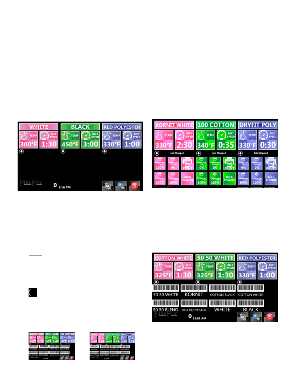
Each top colored section shows the following informa-
tion for each lane:
»PROGRAM NAME: The stored program that the lane
is running.
»TEMP: The temperature that the lane is programmed
to run.
»BELT SPEED: The time in chamber for that lane.
Note: For correct belt speed operation, the belt
sensor wires must be connected correctly as shown
in the Machine Set-Up Guide.
The Center Section of the control panel displays the
following icons:
»: This arrow toggles the windows below for addi-
tional information.
»PREWARMING: If a lane has been set for a prewarm
mode, this will display with a countdown timer.
»JOB STOPPED: If a lane has been paused, this mes-
sage will illuminate.
The Lower Section of the control panel can display the
following information:
»CONVECTION TOP: This is the percentage speed of
convection air movement in the upper air chamber.
»CONVECTION BOTTOM: This is the percentage
speed of convection air in the bottom air chamber.
»EXHAUST: This is the percentage speed of the ex-
haust fan.
»COOLER: This is the percentage speed of the Shirt
Cooling fan.
»BULB POWERS: This lists the percentage of power
each quartz bulb is emitting for this program.
»PRINT: If the unit is equipped with the Linx System,
this print button will output the bar code label for this
program.
Figure 3: Home Screen with lane details
The Lower Section of the control panel can display the
following information:
»BAR CODES: The top 8 program bar codes can be
shown on the screen. These can be scanned with the
Linx Scanners if the machine is equipped with this
option.
Figure 4: Home Screen with Linx Bar Codes
Figure 1: Home Screen
Figure 2: Home Screens with Job Stopped or Prewarming

The Bottom Bar of the control panel displays the follow-
ing information:
»CURRENT TIME: The current time of day.
»: Press this button to access the MAINTE-
NANCE area. If a scheduled task has passed its due
date, the icon will ash.
»: This button will access the SETTINGS menu.
»: Press this button at the end of the day to allow
the dryer to cool off before turning power off.

Working with each control panel icon
DEFAULT
Pressing the DEFAULT button will bring you to the PRO-
GRAMS window. This is where your stored programs are
accessible. To change the program your oven is running,
press one of the saved choices.
After choosing a new program, the screen will return to
the HOME screen and the parameters of the newly chosen
program will appear. The oven will then need time to reca-
librate to any changes in time, temperature and airow.
Any changes in the Middle Window parameters will cause
this label to change to SAVE. If the new parameters need
to be saved as a program, press SAVE. The PROGRAM
NAME window will pop up.
Type the name you wish to refer to this program and select
the . To cancel, press the . The toggles the key board
from upper to lower case. The button changes the key-
board to accented letters. To erase a typo, press the icon.
Changing a parameter does not require the operator to save
a program. The oven will operate on the new parameter as
it is set on the HOME screen.
Figure 5: Main screen at Default
Figure 8: Program Name Screen
Figure 6: PROGRAMS screen
Figure 7: Main screen with selected programs

CONVECTION TOP or BOTTOM
The convection air fan recirculates air over top or from
below the heaters and into the chamber. The speed of the
fans is adjustable and that will adjust the amount of air that
is moved.
To change the fan speed, press CONVECTION TOP or
CONVECTION BOTTOM icon and the SET FAN CON-
VECTION window will pop up. Use the keypad to select
a new fan speed and then press the icon. If you wish to
return to the previously set fan speed, press the icon.
COOLER
The FireFly is equipped with a cooling station at the end of
the oven chamber. A fan system pulls heat from the shirt.
The speed of the fan is adjustable and that will adjust the
amount of air that is moved. The percentage of fan speed is
shown to the left of the icon.
To change the fan speed, press COOLER icon and the SET
COOLER FAN window will pop up. Use the keypad to se-
lect a new fan speed and then press the icon. If you wish
to return to the previously set temperature, press the icon.
TEMP
To change the set temperature, press the TEMP button.
The SET TEMPERATURE window will pop up. Use the
keypad to select a new temperature and then press the
icon. If you wish to return to the previously set tempera-
ture, press the icon.
BELT SPEED
The duration that an item is in chamber is shown to the
right of this icon. It is represented in minutes:seconds. To
change the time in chamber, press BELT SPEED and the
SET CURE TIME window will pop up. Use the keypad to
select a new belt speed and then press the icon. If you
wish to return to the previously belt speed, press the icon.
Figure 10: Set Cure Time
Figure 12: Set Cooler fan
Figure 11: Set Convection Top or Bottom Fan
Figure 9: Set Temperature

BULB POWERS
Each program stored within the FireFly can have specic
bulb intensity levels.
PRINT
This button will print out the bar code label of the selected
program to your label printer included in the Linx system.
The FireFly software allows for the storage of shop main-
tenance tasks. The Maintenance icon gives access to these
tasks and will blink when one of them is due to be complet-
ed.
Press the and the MAINTENANCE window will appear.
There are 12 programs available. Programming these will
be discussed in the section Managing Maintenance Tasks.
Select this icon and the Settings menu will appear. Pro-
gramming these will be discussed in the section Setting
Section.
At the end of the workday, press the .The system will
power down.
Figure 13: Set Bulb Intensity

Working with the Maintenance screen
MAINTENANCE: These are saved shop maintenance
tasks. There are 12 available.
»Click: This is where maintenance task information
is entered.
o FREQUENCY: Toggle through the op-
tions of
§ DAILY
§ WEEKLY
§ MONTHLY
§ YEARLY
o LAST DATE PERFORMED: This pulls
up a calendar. Select the correct date.
o NEXT SCHEDULED DATE: This is
calculated based on the FREQUENCY and
the LAST DATE PERFORMED.
o COMPLETED TASK TODAY: When
the task is due, select the button and the
calendar will reset to the current date and a
new scheduled date will be calculated.
»Click and hold: This allows programs to be reor-
dered.
»: Click and drag any program to the trash to
remove it from the list.
Figure 14:Maintenance
Figure 15:Maintenance details
Figure 16:Maintenance time scheduling
Figure 17: Maintenance save window

The Settings screen
»PROGRAMS: This opens the list of stored pro-
grams.
»Maintenance: This opens the list of Maintenance
Tasks.
»PRINT START STOP JOB TAG: This sends a print
command to the label printer. This is the beginning
and end of the job.
»MODEL: This provides the unit’s model number,
serial number, build date, and power requirements.
»DEFAULT PROGRAM: Use this area to define the
Default program for your FireFly.
»UNITS: Choose the machine units of measure.
o TEMPERATURE: Toggle between Fahr-
enheit and Celsius.
o CURRENCY FORMAT: Choose one.
o ELECTRICITY COST: Enter your cur-
rent electricity cost in kilowatt per hour.
o HOURS PER DAY: Enter your standard
workday length.
o DAYS PER WEEK: Enter your standard
workweek length.
»PRINT PREHEAT TAG: This prints a preheat com-
mand bar code label.
»PRINT RESET HEIGHT TRIP TAG: This prints a
command bar code label to reset the lane when a
garment has tripped the height sensor.
»CALIBRATE TOUCH SCREEN: Contact Brown
Manufacturing Group, Inc. if the touch screen is not
viewing properly.
»POWER MONITOR: The FireFly monitors the pow-
er usage for the unit.
»ADVANCED SETTINGS: There are items within the
system that can be altered when necessary. These
should not be altered without consultation with a
technician at Brown Manufacturing Group, Inc.
Figure 18: Settings window
Figure 19: Programs window
Figure 20: Maintenance window
Figure 21: Power Monitor
Figure 22: Advanced Settings

»RAW DATA: This is the lane information on speed
and temperature.
Working with PROGRAMS: These are the saved pro-
grams. These can be organized within this window.
»Click and hold: This allows programs to be reor-
dered.
»: Click and drag any program to the trash to
remove it from the list.
»: Click and drag any program to the edit icon to
alter any parameter.
»: These arrows toggle from screen to screen of
the 36 available program storage spaces available.
»HOME: This returns the operator to the main
running screen.
»MENU: Returns the operator to the MENU
screen.
»PROGRAM NAME: Select any program button and
that will replace the one currently running. Once
pressed, the system will ask which prompt SELECT
ZONE and then return to the HOME screen. SE-
LECT ZONE is referring to which lane the program
needs to run.
See Working With Control Panel Icons for infor-
mation on the individual buttons.
»BAR CODE ID: If the Bar Code has been prede-
termined within another piece of software, that
number can be entered here.
Figure 23: Raw Belt Data
Figure 24: Programs
Figure 25: Set Zone Temperature
Figure 26: Edit Program Window
Figure 27: Bar Code ID information

Brown Manufacturing Group, Inc.
4661 Stafford Ave. S.W.
Wyoming, MI 49548
Phone: 616-249-0200
Fax: 616-249-3211
www.brownmfg.net
customerservice@brownmfg.net
Conveyor Dryer
Maintenance Guide

Recommended Weekly Maintenance:
•Clean and Adjust Trip Sensor System
•Clean and Adjust Load Sensor System
•Clean Control Panel Fan Filters
•Check Belt Tracking
•Check Bulb Status
Recommended Monthly Maintenance:
•Check Camera Cooling Fan Filters
•Clean Blinders
•Clean Camera Lenses
•Check Bulb Blinders Alignment
•Check Camera Alignment
•Clean Belt Movement Sensor
Clean and Adjust Trip Sensor System:
The trip sensor bridges are located at the front of
the heat chamber (Figure 1). The sensor
indicator lights on top of the bridges should be
on when no object is present on the belt. A strip
of reflective tape is located under the belt
directly underneath the trip sensor bridges, and
should be kept clean to properly reflect the light
emitted by the sensors. The bridges should be
positioned properly such that the sensors are
located directly over the reflective target.
TRIP BAR
TRIP INDICATOR LIGHT(S)
TRIP TARGET
LOAD
SENSOR LOAD TARGET
INDICATOR
LIGHT
Figure 1: Trip Sensor System
Clean and Adjust Load Sensor
System:
The load sensors are located at the front of the
belt (Figure 1). The sensor indicator lights on
top of the sensors should be on when no object
is present on the belt. A strip of reflective tape is
located under the belt, and should be kept clean
to properly reflect the light emitted by the
sensors. The sensors should be positioned
properly such that the sensors are pointed
directly at the reflective target.
Clean Control Panel Filters:
Each section control panel has metal cooling fan
filters located above the control panels (Figure
2). These filters should be kept as clean as
possible. The filters may be removed for easier
cleaning by unscrewing the nuts holding each in
place.

CONTROL PANEL COOLING
FAN FILTERS
Figure 2: Control Panel Filters
Check Belt Tracking:
Each belt should lay in center of the drive and
take-up rollers. If the belt tends to drift to one
side or the other of the roller, the roller should
be adjusted. A red knobs on either side of the
roller allows the roller to be twisted (Figure 3).
The belt will tend to drift towards the side which
is loosest. Thus, pull the roller out on the side
toward which the belt is drifting, or push the
roller in on the opposite side. The belt should
never be pulled so tight that the belt cannot be
shifted on the roller by pulling it firmly with
one’s hands.
BELT TRACKING KNOBS
Figure 3: Belt Tracking
Check Bulb Status:
1) At each drone control panel press
“Menu”
2) Press “Factory Setup”
3) Press “Test Bulbs”
4) Bulb test will report “Successful” if all
bulbs are working correctly, or will
identify those bulbs that are not
working.
Replacing a Bulb:
Before replacing a bulb, it is important to
determine that the bulb is, in fact, the problem.
1) With nothing on the belt, make sure the
lane with the suspect bulb has been
started (use “start/stop job” option on
main kiosk.
2) On drone control panel select “Menu”.
3) Select “Factory Setup”
4) Select “Bulb Setup”
5) Choose belt (zone) in question (Figure
4)
6) Circles at the right of the image
represent bulbs in the zone. (Front bulb
is bottom circle.)
7) Press circle corresponding to suspect
bulb. If the circle turns green, the bulb is
being commanded to turn on.
8) Visibly inspect bulb to see if it is on or
on or not.
If the bulb is truly not coming on, it should be
replaced.
1) Turn off machine.
2) Turn off all disconnect switches (red
knobs on drone panels)
3) Pull sections apart if necessary to access
bulb rack with bad bulb (Figure 5). Note
wire conduit strain while moving
sections.
4) Pull bulb rack out.
5) Remove guards to access bulb wire
connections.
6) Disconnect wires to bulb.
7) Pull wires out of bulb rack metal.
8) Remove bulb from rack by sliding bulb
left and right. (It will probably be
necessary to use fingers to slightly

expand bulb holders to allow bulbs to
slide).
9) Reverse steps to install new bulb.
Figure 4: Bulb Control Screen
SECTIONS PULL APART (NOTE
WIRE CONDUIT STRAIN)
BULB RACKS PULL OUT
BULBS
Figure 5: Bulb Access
Check Camera Cooling Fan Filters:
Inspect camera cooling fan filters above main
heat sections (Figure 6). Replace as necessary.
Clean Blinders:
1) Remove camera access plate (Figure 6)
2) Clean lint & dust from camera cooling
fans and camera bulb blinders.
CAMERA ACCESS PLATE
BLINDER
CAMERA
COOLING FAN
COOLING FAN FILTER
Figure 6: Camera Access
Clean Camera Lenses:
1) Remove camera access plate (Figure 6)
2) Use a lint-free cloth to gently clean any
lint or dust from bottom lens of camera
This manual suits for next models
1
Table of contents
Popular Accessories manuals by other brands

S+S Regeltechnik
S+S Regeltechnik HYGRASGARD AFF Series Operating Instructions, Mounting & Installation

Snom
Snom M700 Admin and installation guide

Det-Tronics
Det-Tronics x2200 instructions

Leviton
Leviton OSW12-MNW quick start guide

OBI
OBI 210563 Original operating manual

Sensormate
Sensormate GE1029-A operating manual