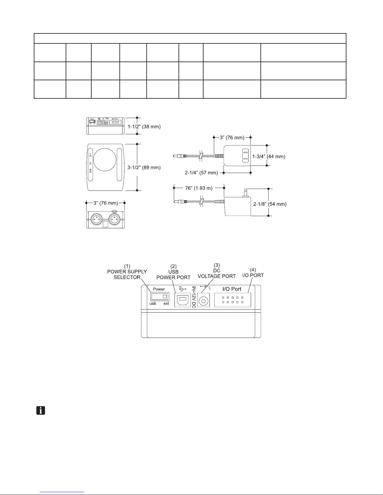
Brunswick led pin light User manual

1
LED Pin Lighting
LED Pin Light
Installation, Pre-Installation & Operation Manual
December 2012/ 47-902714-000

LED Pin Lighting
2
LED Pin Light Installation, Pre-Installation & Operations Manual
© December 2012 by the Brunswick Bowling and Billiards Corporation. All rights reserved.
GS-Series and Pinball Wizard are registered trademarks of the Brunswick Bowling and Billiards Corporation.
Reorder Part No. 47-902714-000
Notice: If available, updates to this manual can be found on-line at www.brunswickbowling.com.
Condential proprietary information. All information contained in this document is subject to change without
notice.
Brunswick Bowling and Billiards Corporation
525 West Laketon Avenue
P.O. Box 329
Muskegon, MI 49443-0329
U.S.A.
231.725.3300

3
LED Pin Lighting
Safety
NOTES AND WARNING
Throughout this publication, “Warnings” and “Cautions” (accompanied by one of the International HAZARD
Symbols) are used to alert the mechanic to special instructions concerning a particular service or operation that
may be hazardous if performed incorrectly or carelessly. They are dened below. OBSERVE AND READ
THEM CAREFULLY!
These “Safety Alerts” alone cannot eliminate the hazards that they signal. Strict compliance to these special
instructions when performing the service, plus training and “Common Sense” operation are major accident
prevention measures.
NOTE or IMPORTANT!:
Willdesignatesignicantinformationalnotes.
WARNING!
Will designate a mechanical or nonelectrical alert which could potentially cause
personal injury or death.
WARNING!
Will designate electrical alerts which could potentially cause personal injury or death.
CAUTION!
Will designate a mechanical or nonelectrical alert which could potentially cause
product damage.
Will designate grounding alerts.

LED Pin Lighting
4
SAFETY NOTICE TO USERS OF THIS MANUAL
This manual has been written and published by the Service Department of Brunswick Bowling and Billiards to
aid the reader when servicing or installing the products described.
It is assumed that these personnel are familiar with, and have been trained in, the servicing or installation
procedures of these products, which includes the use of common mechanic’s hand tools and any special
Brunswick or recommended tools from other suppliers.
We could not possibly know of and advise the reader of all conceivable procedures by which a service might
be performed and of the possible hazards and/or results of each method. We have not attempted any such
wide evaluation. Therefore, anyone who uses a service procedure and/or tool, which is not recommended by
Brunswick, must rst completely satisfy himself that neither his nor the product’s safety will be endangered by
the service procedure selected.
All information, illustrations and specications contained in this manual are based on the latest product
information available at the time of publication.
It should be kept in mind, while working on the product, that the electrical system is capable of violent and
damaging short circuits or severe electrical shocks. When performing any work where electrical terminals
could possibly be grounded or touched by the mechanic, the power to the product should be disconnected prior
to servicing and remain disconnected until servicing is complete.

5
LED Pin Lighting
Table of Contents
Packaging..................................................................................................................................6
Pre-Installation.........................................................................................................................9
Installation LED Pin Lighting ..............................................................................................11
GS-X LED Pin Light Brackets .......................................................................................... 11
A-2 LED Pin Light Brackets ............................................................................................. 14
String Pin Light Brackets .................................................................................................. 17
LED Pin Light MOUNTING............................................................................................. 18
Cabling & Power ............................................................................................................... 20
Communication CABLES........................................................................................................................... 20
Addressing......................................................................................................................... 22
Operation..................................................................................................................................................... 22
Setting the Address of the LED Pin Light................................................................................................... 23

LED Pin Lighting
6
Packaging
Page 1 of 1
MODEL NUMBER CONFIGURATION
BRUNSWICK BOWLING & BILLIARDS CORPORATION
Drawing Number: G6-300001-000 Rev. No: N/C
REV. QTY. PART NUMBER
1.00 47-863001-000 PKG. - LED LIGHT FIXTURE
1.00 47-863002-000 PKG. - DMX CABLE, 10'
DESCRIPTION: MNC - PIN DECK LED LIGHTING, LED LIGHT
DESCRIPTION OF PACKAGE
Page 1 of 1
MODEL NUMBER CONFIGURATION
BRUNSWICK BOWLING & BILLIARDS CORPORATION
Drawing Number: G6-300002-000 Rev. No: N/C
REV. QTY. PART NUMBER
1.00 47-863003-000 PKG. - CONTROLLER FOR PIN DECK LIGHTING, 110V
1.00 47-902714-000 MANUAL - LED PIN LIGHT PRE-INSTALLATION, INSTALLATION
& OPERATION
DESCRIPTION: MNC - PIN DECK LED LIGHTING, DMX CONTROLLER, 110V
DESCRIPTION OF PACKAGE
Page 1 of 1
MODEL NUMBER CONFIGURATION
BRUNSWICK BOWLING & BILLIARDS CORPORATION
Drawing Number: G6-300003-000 Rev. No: N/C
REV. QTY. PART NUMBER
1.00 47-863004-000 PKG. - CONTROLLER FOR PIN DECK LIGHTING, 230V
1.00 47-902714-000 MANUAL - LED PIN LIGHT PRE-INSTALLATION, INSTALLATION
& OPERATION
DESCRIPTION: MNC - PIN DECK LED LIGHTING, DMX CONTROLLER, 230V
DESCRIPTION OF PACKAGE

7
LED Pin Lighting
Page 1 of 1
MODEL NUMBER CONFIGURATION
BRUNSWICK BOWLING & BILLIARDS CORPORATION
Drawing Number: G6-300004-000 Rev. No: N/C
REV. QTY. PART NUMBER
1.00 47-863005-000 PKG. - DMX CABLE, 150'
DESCRIPTION: MNC - PIN DECK LED LIGHTING, HOME RUN CABLE
DESCRIPTION OF PACKAGE
Page 1 of 1
MODEL NUMBER CONFIGURATION
BRUNSWICK BOWLING & BILLIARDS CORPORATION
Drawing Number: G6-300005-000 Rev. No: N/C
REV. QTY. PART NUMBER
1.00 47-862933-000 PKG. - PIN DECK LIGHT MOUNTING BRACKETS
DESCRIPTION: MNC - PIN DECK LED LIGHTING, GSX MOUNTING BRACKET
DESCRIPTION OF PACKAGE
Page 1 of 1
MODEL NUMBER CONFIGURATION
BRUNSWICK BOWLING & BILLIARDS CORPORATION
Drawing Number: G6-300006-000 Rev. No: N/C
REV. QTY. PART NUMBER
1.00 47-863006-000 PKG. - DMX CABLE, 25'
DESCRIPTION: MNC - PIN DECK LED LIGHTING, 25' EXTENSION CABLE
DESCRIPTION OF PACKAGE
Page 1 of 1
MODEL NUMBER CONFIGURATION
BRUNSWICK BOWLING & BILLIARDS CORPORATION
Drawing Number: G6-300007-000 Rev. No:
REV. QTY. PART NUMBER
1.00 12-860812-000 PKG. - BRACKETS, A2 PIN DECK LIGHT, W/HDWR.
DESCRIPTION: MNC - BRACKETS, A2 PIN DECK LIGHT
DESCRIPTION OF PACKAGE

LED Pin Lighting
8
Page 1 of 1
MODEL NUMBER CONFIGURATION
BRUNSWICK BOWLING & BILLIARDS CORPORATION
Drawing Number: G6-300009-000 Rev. No: N/C
REV. QTY. PART NUMBER
1.00 55-860034-000 PKG. STRING PINDECK LIGHT GUARD & MOUNT HDWR.
1.00 55-860026-000 MOUNTING BRACKET & HARDWARE FOR LED PINDECK
LIGHT, STRINGPIN
DESCRIPTION: MNC - STRING PIN MOUNTING BRACKETS & GUARDS FOR LED PIN
LIGHT
DESCRIPTION OF PACKAGE

9
LED Pin Lighting
Pre-Installation
LED Pin Light, 47-863001-000
Volts Hertz AC/DC Phase Amps
Per Unit
Watts Branch Circuit Customer's
Responsibility
100-130 50/60 AC 1 0.5 60 2 wires + ground No more than 12 lights
daisy chained in series
200-240 50/60 AC 1 .25 60 2 wires + ground No more than 12 lights
daisy chained in series
(1) POWER INPUT - 120-240VAC, 5 amp
(2) FUSE - 100-240VAC, 2 amp
(3) MIC VOLUME - Not Used
(4) MIC - Not Used
(5) COMMUNICATION INPUT PORT - Connection for the communication cable from the Deck
Light controller or the previous LED pin light
(6) COMMUNICATION OUTPUT PORT - Connection for the cable to continue the
Communication to additional pin lights
(7) DIP SWITCH CLUSTER- Switches used to set the ID address of pinlight.
IMPORTANT!:Therewillneedtobeanewoutlet/circuitper12lanes.TheoutletontheLEDpinlight
isonlyratedfor5amps.

LED Pin Lighting
10
Controller, 47-863003-000
Volts Hertz AC/DC Phase Amps
Per Unit
Watts Branch Circuit Customer's
Responsibility
100-130 50/60 AC 1 .1 120 2 wires + ground No more than 12 lights
daisy chained in series
200-240 50/60 AC 1 0.5 120 2 wires + ground No more than 12 lights
daisy chained in series
(1) POWER SUPPLY SELECTOR SWITCH - Use to select power to controller from the
"USB" Power Port (2) or the "EXT" DC Voltage Port (3). Needs to be set to "EXT" (3)
(2) USB POWER PORT - Not Used
(3) DC VOLTAGE PORT - Not Used
(4) I/O PORT- Not Used
IMPORTANT!:Programnumbers15,16and24willNOToperatewithvectorcameras.Theprograms
willcausemis-scoringwithVectorscoring.

11
LED Pin Lighting
Installation LED Pin Lighting
GS-X LED PIN LIGHT BRACKETS
If the GS-X Pinsetter has an attached wire way on the front of the machine perform step1, if pinsetter is not
equipped with a wire way proceed to step2.
1. Remove one of the two M8 screws and nuts (Left Hand side of the machine) securing the wire way to
the pinsetter.
Figure1

LED Pin Lighting
12
2. Insert the stud of Left Hand Bracket (47-086148-009) into the hole left by hardware removal in previous
step and secure it with M8 nut (11-051744-001). Refer to Figure2.
Figure2
3. Remove the Right Hand side M8 screw and nut securing the wire way to the pinsetter. Refer to Figure
1.

13
LED Pin Lighting
4. Insert the stud of Right Hand Bracket (47-086149-009) into the hole left by hardware removal in previous
step and secure it with M8 nut (11-051744-001). Refer toFigure3.
Figure 3

LED Pin Lighting
14
A-2 LED PIN LIGHT BRACKETS
1. Find the center of the existing A-2 pin light support. Refer to Figure4.
Figure4
2. Position 1 bracket (12-610001-000) 20" to the left of the center line of the pin light support and one
bracket 20" to the right of the center line of the pin light support. Bracket must extend toward foul line.
Refer to Figures4&5.

15
LED Pin Lighting
Figure5
3. Thread a 1/4-20 x 1" socket head set screw (11-103171-009) in the nut on the front (toward the foul line)
side and tighten to secure the bracket to the pin light support. Refer to Figure6.

LED Pin Lighting
16
Figure6
4. Thread a 1/4-20 hex nut (11-125100-009) onto the set screw and tighten to lock set screw.
5. Thread a 1/4-20 x 1" socket head set screw (11-103171-009) in each of the nuts on top of the bracket.
Alternately tighten the set screws until the bracket is square and perpendicular to the pin light support.
6. Thread a 1/4-20 hex nut (11-125100-009) onto the set screw and tighten to lock set screw.

17
LED Pin Lighting
STRING PIN LIGHT BRACKETS
Figure 7

LED Pin Lighting
18
LED PIN LIGHT MOUNTING
1. Loosely attach Pin Deck Light to brackets with (1) M6 Screw and (2) External Tooth Lockwashers on
each end of the light. Refer to Figure8.
Figure 8

19
LED Pin Lighting
2. Adjust the angle of the light to the desired position and tighten the screws on both ends of the light.
Refer to Figure9.
Figure 9

LED Pin Lighting
20
CABLING & POWER
Communication CABLES
1. Connect the male end of the 150' (45.72 m) home run cable to the "Communication Output" port on the
controller (P/N 47-863003-000). Refer to Figure10.
Figure10
2. Connect the female end of the home run cable to the "Communication Input" port on the rst LED pin
light. Refer to Figure10.
NOTE:Thehomeruncablecanbeattachedtothepinlightofeithertherstorlastlane.
Communicationfortheremainingpinlightswilldaisychainfromthatpoint.
Table of contents