5
1 – INTRODUCTION
The purpose of this manual is to provide all the
information required for the correct installation and
maintenance of model 6400 safety valves.
2 – DESCRIPTION
The model 6400 safety valves have been designed,
manufactured and tested in compliance with the
Pressure Equipment Directive 2014/68/UE Category IV
and Directive 2014/34/UE (ATEX) Group II Category II.
The model 6400 safety valves are safety devices whose
main function is to protect all kinds of pressurised
containers, with gases, vapours, liquids or mixtures,
from excess pressure.
For improved performance, the internal parts of the
valve have been designed depending on whether the
application is to work with gas of liquid. In both cases,
the valve opens instantly (pop).
Model 64G.- Designed to work with gases or vapours.
Model 64L.- Designed to work with liquids or gas-liquid
mixtures.
Depending on the requirements of the application, they
can be supplied as conventional valves (C), bellows
valves (F) or as piston valves (P).
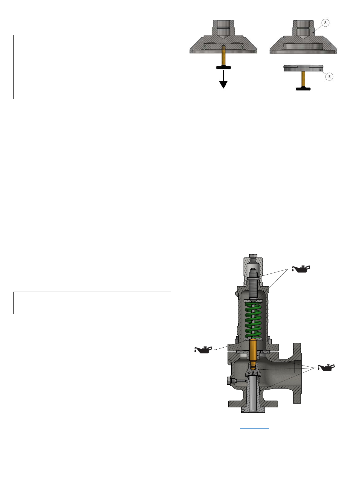
They are constructed with an angle of 90º between the
inlet and outlet connections. The flanged body has a
large internal capacity to avoid backpressures when the
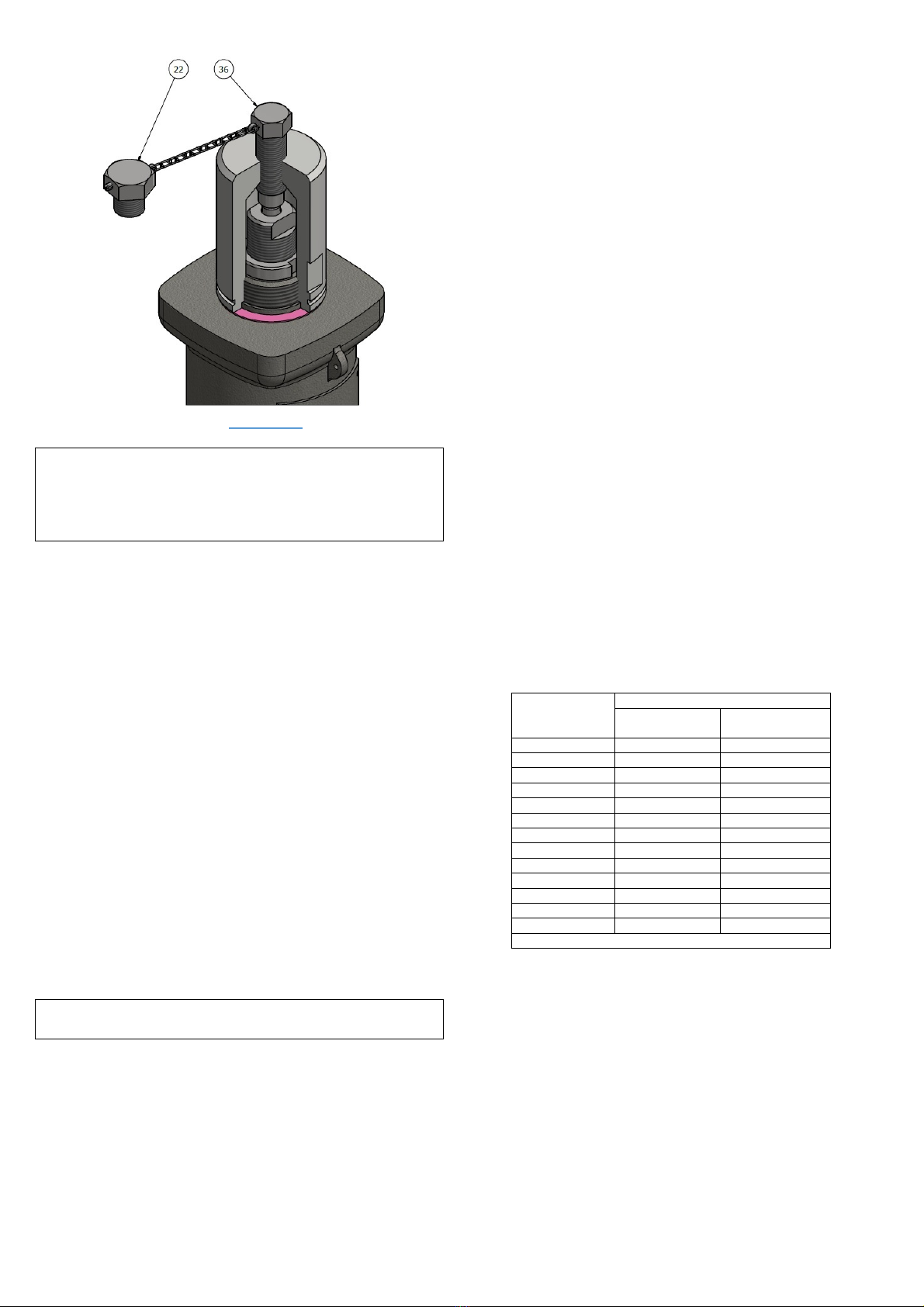
valve discharges. Other parts are: a fixed complete
nozzle easy to disassemble, a closed bonnet, an
helicoidal spring-loaded, a disc holder mechanism
designed accurately to obtain a good discharge
coefficient with both gases and liquids. Perfect alignment
of the guided components, avoiding rubbing and
premature wear and tear.
All safety valves are calculated and manufactured for a
specific application. If you wish to reuse an existing
valve for any other application, you must contact the
V.N. Technical Department for the corresponding
adaptation study.
3 – TRANSPORTATION AND STORAGE
The internal components of the safety valve are
precision-manufactured and fitted in such a way that
they will remain perfectly aligned.
Rough handling can damage the closing surfaces or
unalign the internal parts of the valve, causing leaks
or malfunctions. Therefore, handle the safety valve
with care.
Do not remove the adhesive protective disc that covers
the inlet and outlet flanges until the valve is in its final
position. This ensures the protection of the closing
surfaces and prevents foreign bodies from entering into
the internal chamber of the valve.
Carbon steel valves are protected externally with a
phosphated anticorrosive primer coat and enamelled
final coat which provides the valve a strong external
protection from oxidation. The studs and nuts are
protected with a dichromatized, a protection electrolytic
treatment.
If the valves have to be stored for a long period of time,
it is better not to remove them from their packing. It is
essential for the adhesive disc that protect the inlet and
outlet flanges not to be removed until their installation. It
is recommended the warehouse atmosphere to be
clean, dry and protected from open-air. If this is not
possible, the valve must be appropriately protected to
prevent from deterioration.
4 - INSTALLATION
Correct installation is essential for the safety valve to
operate correctly.
Remove the adhesive protective discs from the inlet
and outlet flange.
Once the valve has been fitted, it will probably need to
be serviced in the short term when the valve has not
been installed correctly, when the protected line is
contaminated with dirt or slag, when it is given a use for
which it was not designed or when the valve is not
handled correctly.
Before fitting the valve, make sure that the valve is
correct by checking the identification plate. Make sure
the seal has not been broken (otherwise, the set
pressure and tightness have to be checked again). Make
sure the valve is perfectly clean and that there is no dirt
inside the nozzle or in its body. If necessary, perform a
blow.
The pipe, the connection flanges and the valve holders
must be perfectly clean. You must be completely certain
that there are no foreign bodies such as particles on the
gaskets, slag, and/or dust which could be deposited on
the closing surface between the disc and the nozzle.
All the bolts that fasten the valve to the container must
be cross-fastened evenly to prevent deformations to the
body of the valve.
When the discharge is performed through a pipe to the
atmosphere, make sure that no water, dirt or
condensation accumulates inside the body of the valve.
The free discharge pipes must be fastened securely to
prevent the stress produced during discharge being
withstood by the neck of the valve.
The valve must always be fitted in vertical position. The
valve inlet pipe from the equipment or the installation
must be direct and as short as possible. The return
connection to the tank must be curved to avoid
turbulence and to enable the discharge of the fluid by
the valve.