BSC BSV175 User manual

Content
1. Forward
2. Product Description
3. Specification
3.1 Operation and Location
3.2 Performance data
3.3 Mounting Dimensions
4. Installation
4.1 Safety information
4.2 Overview of the System
4.3 Cooling Water Piping
4.4 Oiling
4.5 Electrical Wiring
4.6 Gas Inlet
4.7 Gas Outlet
4.8 Gas Ballast
4.9 Leakage Testing
5. Operation
5.1 Starting
5.2 The Controller of Gas Ballast
5.3 Condensing steam
5.4 Clearance of lubricated oil
5.5 Halting
6. Maintenance
7. Storage
8. Warranty
9. Troubleshooting
10. Main replaceable parts list

1. Forward
We sincerely appreciate your selection of BSV series vacuum pump.
On receiving the product, please check on the model fitting your order and any damage
caused by transportation. Please contact with BAOSI or supplier once finding out any damage,
defect or lost of spare parts.
Shipment with care.
Important precautions
The manual instructs the installation, operation and maintenance of BSV175,BSV275. Please
strictly follow the manual for the safety and efficient use of the product.
This product must be installed, operated and maintained by trained personnel. And please
comply with national and local safety regulations or laws.
WARNING
Non compliance with the following precautions may result in significant
personal injury
Cut off all electrical power related to the vacuum pump before maintenance and inspection.
The non professional personnel shall not disassemble, repair or alter the vacuum pump.
Otherwise the failure may cause fire and injury as well as the abnormal operation of the
vacuum pump.
Blocking the discharge hole while the vacuum pump is working will lead to the increasing of
internal pressure, which results the break of pump chamber and oil level check window, oil
leakage and motor overload.
The vacuum pump is not suitable for extraction of the mixed gas of which oxygen occupy more
than 21%, or other easy reactant gas.
Do not use the vacuum pump in the place which can easily catch explosion to avoid injury or
fire.
Do not use the vacuum pump in the place which can lead to condensation or is full of powder
or granular dry materials to avoid the materials getting into the pump to contaminate oil inside.
Do not use the vacuum pump in the condition of low oil level or oil free to promote the
performance and extend the service life of vacuum pump.

Check the oil level timely when the vacuum pump is working.
The ambient temperature of working condition shall be 5~40°C to ensure the normal heat
radiation of the vacuum pump.
Please don't place flammable items around the motor and pump body, so as not to cause fire.
Keep adequate ventilation to avoid the rising of temperature causing burn and fire.
Do not touch the vacuum pump when it’s working or just halted for the surface temperature
can reach 80°C. Please take safety precaution if necessary.
Do equip with the overload protection device for motor.
L1 L2 L3: 3 phases A/C
Qs: air switch
FU1: fuse
KM1: contact
FR: thermal relay
U1 V1 W1: motor terminal
M3~: 3 phases motor Drawing 1 –Motor electrical wiring (example)
2. Product Descriptions

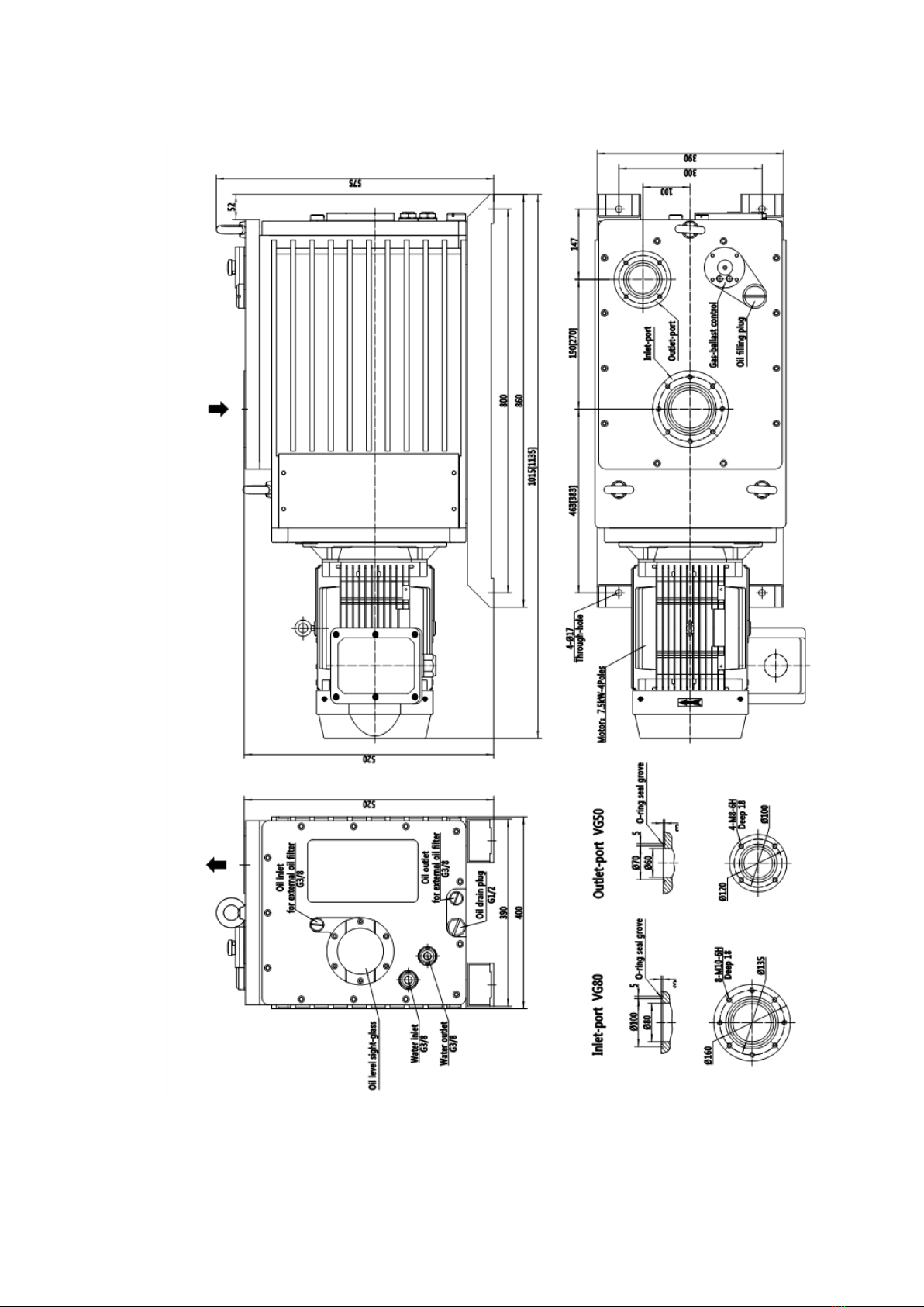
BSV175/BSV275 shown on drawing 2.
BSV175/BSV275 pump is a two stage direct coupling oil rotary vane vacuum pump, which can
work in the laboratorial and industrial environment for long time. It is directly driven by a
three-phase four pole motor with flexible coupling. The pump is mounted on a steel rail.
Pump is equipped with two high and low vacuum rotors and cylinder assembly, as well as
integral vane pump.
The rotor is arranged in an eccentric ground in the pump cylinder, and two rotary vanes
separate the chamber into several spaces of which the volume varies periodically with the
rotation of rotors.
Vanes driven by the rotors rotates against the wall of chamber with the help from centrifugal
force and air spring, which leads to the separation of air inlet and outlet. The air intake cavity
inhales as its volume expands periodically. The exhaust cavity compressed the gas
periodically as its volume decreases. By the pressure from compressed gas and oil, discharge
valve slice is pushed away to obtain vacuum.
Vane oil pump provides lubrication. Oil goes through the oil inlet pipe and is inhaled into the
spring distribution valve. The valve will distributes a little pressurized oil into the vacuum
chamber and will transport redundant oil to the storage cavity by bypass.
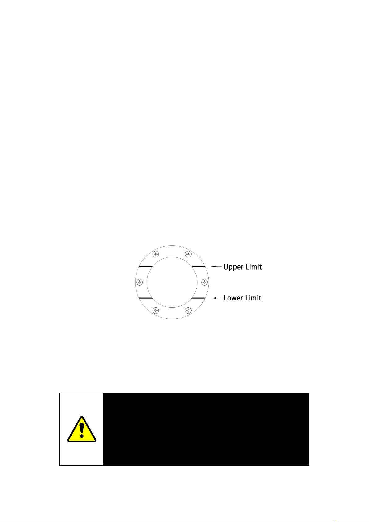
Check the oil level and quality through oil level sight glass(6). There is a oiling plug(2) screw
top of the oil cavity and draining plug screw(8) bottom of it.
The air inlet is VG80 flange. Gas outlet is VG50 flange. The oil-out port for external oil filter is
G3/8. The oil outlet (7) and the oil return port (5) is for external oil filter.
The water cooling system is adopted. Suggest adopting thermostatic control valve to adjust
the flow of water so that the vacuum pump can work at optimum working temperature as well
as keep water economy to prompt gas ballasting.
The function of gas ballasting
The gas ballast valve (3) should be turned on when discharge or inhale high load steam. The
air or inactive gas is fed into the low pressure cavity of the pump through the gas ballast inlet to
prevent condensation of vapor carried by the process gas, which can reduce oil pollution and
pump corrosion caused by condensation of steam from the process gas.
A filter / muffler is installed in the gas ballast system to prevent dust from entering the pump
and to reduce noise.

1. Air inlet7. The oil-out port for external oil filter G3/8.
2. Oiling plug screw 8. Draining plug screw
3. The gas ballast valve 9. Cooling water outlet G3/8
4. Discharge vent 10. Cooling water inlet G3/8
5. Oil return port is for external oil filter 11. Motor terminal
6. Oil level sight glass
Figure (2) –BSV175[BSV275] rotary vane vacuum pump

3. Specifications
3.1 Operation and Location
Ambient temperature range for location 12~40°C
The pump reaches ultimate vacuum when the ambient temperature is 20 °C . The normal
surface temperature of the pump is 50~70°C
Maximum humidity for operation is 90%RH
Ambient temperature range for location is -30~70°C
3.2 Performance data
Table 1 - performance data
Items
BSV175
BSV275
Unit
Pumping speed
50Hz
160
255
m3/h
60Hz
196
306
m3/h
Motor rotary speed
50Hz
1440
1440
r/min
60Hz
1720
1720
r/min
Ultimate vacuum
Gas ballasting off
5×10⁻¹
5×10⁻¹
Pa
Gas ballasting on
2
2
Pa
Maximum outlet pressure
(full flow)
Psig
0.5
0.5
bar
Psia
1.5×10⁵
1.5×10⁵
Pa
Air inlet
Flange with O-ring
VG80
VG80
DN
Air outlet
Flange with O-ring
VG50
VG50
DN
Capacity of pump oil
Max
25
28
L
Min
20
23
L
Noise level
1m away
73
75
dB(A)
Weight
Include motor
230
255
kg
Remark
1. The “ultimate vacuum” on table 1 refers to the measurement tested by pirani gage
with the using of BAOSI vacuum pump oil BSO-68. The measurement tested by
MaLeod gauge is 5×10⁻²Pa.
2. Different vacuum pump oils are different in vapor pressures, dynamic viscosities
and quality. Please use BSOAI vacuum pump oil to avoid affecting the performance
and service life of the pump.

3.3 Mounting Dimensions
Figure (3) –BSV175[BSV275] installation drawing

4. Installation
4.1 Safety information
The installation of vacuum pump should be in accordance with the following safety
instructions and handled by the trained technical personnel.
Cut off all electricity before the installation.
Necessary to adopt protection method when touching contaminative parts
Exhaustion and purge are needed before the installation.
Ensure that the installation personnel should be familiar with the safety procedures
related to pump oil and vacuum system. Appropriate preventive measures should be
taken to avoid the oil mist and the skin exposing to the pump oil for long-term
exposure causing harm.
WARNING
The maximum weight of the pump is about 255kg. Using proper
lifting equipment for installation.
The ring on vacuum pump should be connected with the mechanical lifting equipment
when conveyed.
The vacuum pump should be installed on a horizontal stable platform. Ensure that it’s easy
access to the oiling plug screw and draining plug screw as well as has a well sight of oil
level sight glass.
If the pump is placed within a housing, good ventilation should be guaranteed and the
space between the vacuum and the housing should be less than 25mm.
4.2 Overview of the system
The following points are considerable when design the vacuum system:
Preheat the pump before exhausting and inhaling. Separate the pump and user’s
vacuum system by specific valves to keep vacuum of the pump before turning off.
Prevent processed gases from conveying high heat into the pump to avoid overheat
and jammed.
The surface temperature of the pump working at high ambient temperature can
exceed 70°C with large gas flow. Users should take appropriate precautions to
prevent direct contact with the hot surface.
Ensure the exhausting pipes unblocked. If the user uses the exhaust isolation valve,

ensure the pump can’t be started with valves closing.
Cooling water is needed.
4.3 Cooling Water Piping
Two G3/8 inch internal screw pipes should be connected with the source of cooling water.
Recommended minimum flow of cooling water at 20℃is 120L/h.
If you use a constant temperature control valve to control the temperature, the pump can
achieve the best operating temperature and improve work efficiency.
4.4 Oiling
Follow these steps to oil the pump. Please refer to figure 1 for the following numbers.
1. Remove the oiling plug screw.
2. Oil the pump till the max level on sight glass(6). Drain the redundant oil through
Draining plug screw(8).
3. Check the oil level in several minutes. Add more oil if it not reach the max level.
4. Position the oiling plug screw with hands properly.
Figure(4) - Oil level sight glass
4.5 Electrical Wiring
The connection between the pump and power source
WARNING
It is necessary to ensure that the electrical installation of the pump motor
meets the requirements of the user and the local safety requirements.
The circuit must have proper overload protection devices and must be
properly grounded.

ATTENTION
If the pump motor can be used in more than one voltage, the user must carry out the
correct configuration of the supplied voltage for the motor. Otherwise, the motor will be
burned, while there is a risk of fire.
The pump will automatically restart when power restores after interrupted. The adoption
of manual reset electric control device does not lead to automatically restart of the pump.
We recommend that the use of motor connected with thermal over-current protection
starter or circuit breaker and adjust appropriate current to the over-current protection.
Figure (5) - triangular connection, three-phase motor
Figure (6) - Y - shaped connection, three-phase motor
Check Rotary Direction

WARNING
Ensure the correct rotary direction if the motor to avoid damage the pump and vacuum
system.
1. Observe the cooling fan from the fan cover of the motor.
2. Turn on the motor for several minutes then turn it off.
3. Check whether the cooling fan of the motor rotates in the direction shown by the arrow
on the motor mounting plate. If the direction is not correct,
Cut off the power
Remove cap of terminal box and exchange any two of L1, L2, L3. Then back the cap.
Turn on the pump and check the rotary direction of fan.
4.6 The connection between air inlet of the pump and user’s system
Use VG80 standard pipe joint to connect the pump with user’s system. Pay attention to
following points
In order to achieve the best pumping speed, make sure that the pipe connecting with
air inlet should be as short as possible and less elbow exist. The internal diameter
should be smaller than that of air inlet.
Hold the vacuum pipes steadily in case of too much stress on the joints
If it’s necessary, use soft bellows to reduce the vibration and stress on joints. The
withstanding pressure of soft bellows should be higher than the maximum pressure
produced by the vacuum system. If the pump is installed on the shock absorber, the
soft bellows must be used.
Use proper valves to separate the pump from user’s system if vacuum status is
needed with the pump off.
Equip with the filter on air inlet of the pump if the pump is used for the exhausting and
inhaling of condensing steam or placed in dusty occasion.
Ensure that the surface of seals are clean and free of scratch.
4.7 The connection between gas outlet and user’s system

WARNING
Connect the exhaust port of the pump with the proper treatment
device to prevent dangerous gases and vapors from discharging
directly.
Use standard VG50 Flange pipe connect the gas outlet with proper treatment device. Pay
attention to the following points.
The exhaust system must be properly configured to ensure that the highest exhausted
pressure in full flow does not exceed 0.5bar (psia 1.5bar, 1.5x10⁵Pa)
In the following situations, we recommend that users install oil mist filter at the pump's
exhaust port:
In the situation that the pump works with the gas ballast on
In the situation that the inlet pressure exceeds 1000Pa for long
In the situation that the pump starts working at atm.
Oil mist filter will trap the oil in the pump. If the oil is not contaminated, it can be reused.
4.8 Gas ballasting
The vacuum pump has two gas ballasting inlet(two G1/4 internal screws). Either can be
used while the other one has to be blocked.
The gas ballasting inlet can be open or installing a gas ballasting control valve to adjust
the inlet air volume remotely.
4.9 The leakage testing
Carry out the leakage test after the completion of the vacuum pump installation. Any leakage
should be blocked.
5. Operation
5.1 Start
WARNING
Never stem the outlet of the pump or allow the exhausting pressure
higher than 0.5 bar psig, or it can cause the explosion of oil tank and
hurt people around.

1. Connect the cooling water system.
2. Turn on the power.
3. The level of oil drops by 3-5mm through oil level sight glass, which means the vacuum
pump has working with oil circulation.
4. If the pump is working without oil circulation, let the pump works with the air inlet
connected with atm. for 30 seconds. Then check the oil level to see whether it drops
by 3-5mm.
5. The pump can run continuously for a long time in the normal condition. However we
suggest that customer should regularly check the vacuum pump every two weeks. If
the vacuum pump often work in heavy load or the gas ballasting controller connects
with atm. all the time, check the pump more often.
5.2 The gas ballasting controller
WARNING
The consumption of oil and noise would increase while the gas ballasting is connecting
with the atmos.
Use the gas ballast controller (3) to change the amount of air (or inert gas) into the pump's
low vacuum section. Using gas ballast controller can prevents steam inside of pump
from condensing which would lead contamination to the pump.
Close the gas ballast controller by clockwise rotation. Open it by anticlockwise rotation.
5.3 Condensing steam in the pump
Gas ballast should be open when the processed gases contain large portion of
condensing steam.
1. Close the isolation valve of the vacuum system.
2. Open the gas ballast controller by anticlockwise fully and let the pump works for 30
minutes to preheat the oil, which helps to prevent the steam from condensing inside.
3. Open the isolation valve of the vacuum system and let the pump work with gas ballast
controller open.
5.4 The decontamination of oil pump
The pump oil is supposed to be clear. If there is turbidity or discoloration, the oil has been
contaminated by the processed steams
1. Check the oil quality through the oil level sight glass.
2. Close the isolation valve if the oil is turbid or discolored.
3. Fully open the gas ballast controller by anticlockwise rotation.
4. Start the pump till the oil gets clear.
5.5 Halting

When the gas ballast controller is on, Halting or accidental shutdown may lead to the
reverse rotation of the pump’s drive shaft and the rise of system pressure. The gas ballast
control valve should be adopted to avoid this situation.
We suggest decontamination of the oil before halting to avoid the contaminant damaging
the pump.
1. Carry out the decontamination according to need.
2. Close the isolation valve.
3. Close the gas ballast controller by clockwise rotation.
4. Cut off the power.
5. Close the cooling water valve.
6. Maintenance
6.1 Safety information
WARNING
The following safety instructions must be comply with and adopt
appropriate precautions. Otherwise the injury to personnel and
damage to machine may happen.
1. The maintenance job must be completed by trained technical personnel in the
condition that obey the national and local safety regulations.
2. Ensure that the maintenance personnel are familiar with the safety procedures related
to pump oil and vacuum system.
3. Check the completeness of necessary spare parts before working.
4. Cut off all the power connected with the vacuum pump.
5. Cool the pump to safe temperature.
6. No further use of the broken O-rings and seals
7. Check the rotary direction of the pump again after maintenance.
8. Fluorinated materials are safe in normal use. However if the pump is used improperly
or subject to fire, it may overheat to more than 310℃with the decomposition of
fluoride materials into dangerous substances like hydrofluoric acid.
9. If the user has connected or disconnected the vacuum joint or exhaust joint, leakage
test should be carried out after maintenance. Seal the leakage if it exists.

10. The process chemicals will pollute the pump and pump oil when the pump is working.
Decontaminate the pump after maintenance if there is contamination as well as adopt
necessary precaution to protect personnel.
11. Ensure the stability of protective device before restart the pump.
6.2 The maintenance plan
Table (2) shows the routine maintenance plan for the vacuum pump. If the vacuum pump
often inhale and exhaust corrosive gases or the gas ballasting controller connects with
atm. all the time, maintain the pump more often. Adjust the maintenance plan if
necessary.
Operation items
Period
Check oil level
Every week
Replace oil
Every 6 months
Replace gas ballast filter
Every 3000 hours
Check and clean air inlet filter
Every year
Clear the cover of motor
Every year
Clean and overhaul the pump
Every year
Test the motor
Every year
Replace the vanes
Every 3 years
Table 2 Maintenance plan
6.3 Check the oil level
1. Check the oil level regularly when the pump is running. Halt the pump before adding
oil.
2. Adding oil timely when the oil level is near or below the minimum oil level. Drain the
redundant oil if the oil level exceed the maximum level.
3. If the pump oil is contaminated and can’t be cleaned, which affecting the performance
of the pump, replace the oil.
6.4 Replacement of the oil
1. Start the pump for 10 minutes to preheat the oil (Reduce the viscosity of the oil to
make it easy to flow out), then halt it.
2. Cut off the power. Isolate the pump from the vacuum system.
3. Remove oiling plug screw.
4. Put a proper container under the drain port and remove the drain plug screw so that

the oil can flow into the container.
5. If the discharged oil the pump is contaminated, add clean oil from drain port and let it
flow out from the pump.
Repeat this step until the pump's oil storage tank is flushed clean.
6. Position the drain plug screw. Adding clean oil from the oiling port till the oil level
reach the maximum level.
7. Position the oiling plug screw.
8. Connect the pump with vacuum pump.
6.5 Check and clean the air inlet filter
Air inlet filter can keep micro particles away from the pump cavity, thereby reducing the
wear of pump parts. Check the air inlet filter before replacing the oil. Clean the filter if
necessary. Steps as follows:
1. Disconnect the power source from the pump.
2. Disconnect the pump from the vacuum system.
3. Remove the filter from air inlet.
4. Clean the filter in proper cleaning solution then dry it.
5. Position the filter on air inlet.
6. Reconnect the pump with the vacuum system.
7. Reconnect the power source with the pump.
6.6 Clean the cover of motor
Keep the motor cover clean. If the air flowing through the motor is blocked, the pump will
overheat.
1. Disconnect the pump from power source
2. Clean the cover of motor with brush and dishcloth
3. Reconnect the pump with the vacuum system.
6.7 Clean and overhaul the pump
Disassemble and clean the vacuum pump thoroughly. Replace the spare parts according
to main replaceable parts list.
7. Storage
WARNING
The seals in the pump can get permanent damaged if the pump is stored at -30℃. Check
the pump thoroughly before use if the pump has been stored more than 1 year. Clean or
overhaul the pump if necessary.
The steps as follows,
1. Halt the pump
2. Disconnect the pump from the power source.

3. Close the cooling water valve
4. Disconnect the joints of cooling water from the pump and discharge water from the
pump.
5. Disconnect the pump from the vacuum system
6. Replace the clean oil
7. Install protective covers on air inlet and outlet.
8. Store the pump in the cool and dry environment.
Disposal
The disposal of the pump and spare parts should be accordance with the national and
local safety rules and regulations. Notice the items contaminated by hazardous production
materials.
No burning of fluorine rubber seals and O-rings.
8. Warranty
8.1 Warranty clause
The product has been inspected strictly before shipment and the warranty lasts 1 year
since the date of delivery. Any breakdown out of quality happens during the warranty,
our company is responsible for free repair and replacement.
8.2 Exception from liability
1. Past the warranty period
2. Damage made by man or external factors (natural disasters, war, etc.)
3. Not follow the instruction manual and the breakdown caused by operation in improper
way.
4. Any transformation, decomposition and repair to the product without our consent.
5. Breakdown caused by working in abnormal situation (Strong electromagnetic, strong
radiation, high temperature, high humidity, flammable gas environment, corrosive gas
environment, dust, etc.)
6. Breakdown caused by working in the improper conditions.
7. Breakdown caused by noise.
8. Breakdown caused by consumables

9. Troubleshooting
Table 3 Failure analysis and troubleshooting
Breakdown
Probable cause
Solution
The pump
can’t start
Power fuse burned
Replace the power fuse
Supplied voltage not match motor rating
voltage
Check the electrical source
and connection
Breakdown of motor
Overhaul or replace the motor
Ambient temperature is too low, the
viscosity of oil increased
Raise the temperature or
replace the low viscosity oil
Pump oil is contaminated and it’s viscosity
increase
Replace the clean oil
Exhaust filter or pipe blocked
Clean the filter and pipe
The pump jammed
Overhaul the pump
The pump
can’t reach
ultimate
vacuum
The error of motor rotary direction
Check the rotary direction
The gas ballast valve is open
Close the gas ballast
Intake pipe diameter is too small or too
long.
Make the correct configuration
of the air inlet pipe
The leakage of vacuum system and pipes
Block the leakage
Air inlet filter blocked
Clean the air inlet
Air inlet pipe or filter blocked
Clean air inlet pipe or filter
Oil is contaminated or inappropriate
Replace the oil
The quantity of oil is insufficient
Replenish pump oil timely
Low the pumping rate
Adopt the pump with proper
pumping rate
Measurement technique or instrument is
not suitable
Use the correct measuring
instrument and calibration
Pump oil circuit blocked
Disassemble the pump and
clean the circuit.
Low
pumping
rate
The air inlet is too small or too long
Correct configuration of air inlet
pipe
Air inlet pipe or filter blocked
Clean air inlet pipe or filter
Air inlet filter blocked
Clean air inlet filter
Leakage of vacuum system or filter
Block the leakage
Pumping rate is relatively low
Adopt the pump with proper

pumping rate
Oil is contaminated or inappropriate
Replace the oil
Abnormal
noise
“KA TA” noise when start or halt
Transient irregular motion of the
vanes
The loose of motor coupling
Check the coupling
Breakdown of the motor
Overhaul or replace the motor
Oil is contaminated by solid particles
Replace the clean oil
The vanes jammed or damaged
Check and replace the vanes
Spare parts inside of pump broken
Check and replace the broken
spare parts
High
temperature
of pump
High ambient temperature
Lower the temperature
Insufficient flow of cooling water
Supply sufficient cooling water
High power voltage
Correct the power configuration
Oil is contaminated or inappropriate
Replace the pump oil
Insufficient oil quantity
Replenish pump oil
Discharge filter or pipe blocked
Clean discharge filter or pipe
High temperature of inhaled gas
Lower the temperature of
inhaled gas
Continuous operation under high pressure
Larger the flow of cooling water
External
leakage of
pump
Seal wear or aging
Replace the seal
Oil tank seal gasket damaged
Replace the seal gasket
The leakage of gas ballast controller
Replace the gas ballast filter
Loose of sealing plug
Tighten sealing plug
O-ring of sealing plug aging
Replace O-ring
Fail to
completely
keep the
vacuum
Gas ballast open
Close gas ballast controller
then halt the pump
seal components broken or lost
Check seal components
Broken Anti suction valve
Replace anti suction valve
Seal broken
Replace seal
Exhaust valve broken
Replace exhaust valve

10. Main replaceable parts list
Location
Items
Specification
Material
Quantity
Coupling
Elastomer
GR38
------
1
Bearing
Grease seal
30*40*7
FKM
1
Grease seal
40*52*7
FKM
3
First cylinder
First exhaust valve
------
FKM
1
Second cylinder
Second exhaust valve
------
FKM
1
Upper cover plate
Sealing gasket
------
Cork pad
1
Front cover plate
Sealing gasket
------
Cork pad
1
Gas ballast
Filter element
------
Felt
2
Cylinder
O-ring
A-111,AS568
FKM
1
O-ring
A-114,AS568
FKM
1
O-ring
A-216,AS568
FKM
2
O-ring
A-331,AS568
FKM
1
O-ring
A-341,AS568
FKM
1
O-ring
132*2,M
FKM
1
O-ring
165*2,M
FKM
2
O-ring
S9,JIS
FKM
2
O-ring
S16,JIS
FKM
2
O-ring
S120,JIS
FKM
1
O-ring
S145,JIS
FKM
1
O-ring
P9,JIS
FKM
1
O-ring
P15,JIS
FKM
2
O-ring
G45,JIS
FKM
1
O-ring
G85,JIS
FKM
1
O-ring
G115,JIS
FKM
1
O-ring
G200,JIS
FKM
1
Plug screw
O-ring
P18,JIS
FKM
2
O-ring
P24,JIS
FKM
1
O-ring
P36,JIS
FKM
1
Oil level sight glass
O-ring
G100,JIS
FKM
1
Exhaust port
O-ring
V100,JIS
FKM
1
Air inlet port
O-ring
V70,JIS
FKM
1
This manual suits for next models
1
Table of contents
Other BSC Water Pump manuals
Popular Water Pump manuals by other brands

Rapid
Rapid GTK 60/2-P Operation manual

M&C
M&C MP Series instruction manual

Agilent Technologies
Agilent Technologies Turbo-V 903 user manual

Xylem
Xylem GOULDS Prime Line Marlow Series Installation, operation and maintenance instructions

Doheny's
Doheny's 90500 Installation, operation & parts

Raymarine
Raymarine M81120 installation guide