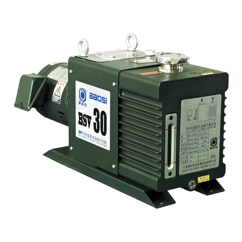
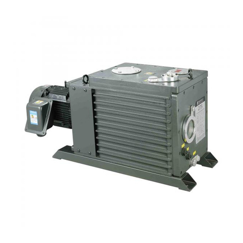
BSC SRV300 User manual

Instruction Manual
VERSION
:
1.0
Single-stage oil-sealed rotary vane vacuum pump
SRV300

Content
1 Introduction……………………………………………………………………………………………………………………………………1
2 Design and function………………………………………………………………………………………………………………………3
3 Application……………………………………………………………………………………………………………………………………4
4 Technical data…………………………………………………………………………………………………………………………………4
5 Installation diagram…………………………………………………………………………………………………………………………5
6 Installation and Operation
6.1 Installation………………………………………………………………………………………………………………………………6
6.2 Inlet side…………………………………………………………………………………………………………………………………6
6.3 Outlet side………………………………………………………………………………………………………………………………7
6.4 Oil filling…………………………………………………………………………………………………………………………………8
6.5 Electric connection…………………………………………………………………………………………………………………8
6.6 Startup……………………………………………………………………………………………………………………………………9
6.7 Operation………………………………………………………………………………………………………………………………9
6.7.1 Pumping of Non-condensable Gases……………………………………………………………………………………9
6.7.2 Pumping of Condensable Gases and Vapors…………………………………………………………………………9
6.7.3 Cyclic process ………………………………………………………………………………………………………………………10
6.8 Stop ……………………………………………………………………………………………………………………………………11
6.9 Ultimate pressure …………………………………………………………………………………………………………………11
7 Maintenance …………………………………………………………………………………………………………………………………12
7.1 Maintenance schedule …………………………………………………………………………………………………………12
7.2 Checking the oil ……………………………………………………………………………………………………………………13
7.2.1 Oil level ……………………………………………………………………………………………………………………13
7.2.2 Oil condition ………………………………………………………………………………………………………………13
7.3 Oil change ……………………………………………………………………………………………………………………………13
7.4 Replacing oil filter …………………………………………………………………………………………………………………14
7.5 Cleaning the Dirt trap …………………………………………………………………………………………………………14
7.6 Checking the Anti-Suck back valve ………………………………………………………………………………………15
7.7 Radiator cleaning …………………………………………………………………………………………………………………15
7.8 Motor fan cover cleaning ……………………………………………………………………………………………………15
8 Disposal and store ………………………………………………………………………………………………………………………16
9 Scrap Processing …………………………………………………………………………………………………………………………16
10 Warranty ……………………………………………………………………………………………………………………………………16
11 Disclaimer …………………………………………………………………………………………………………………………………17
12 Troubleshooting …………………………………………………………………………………………………………………………18
13 Check Sheet for Repair ……………………………………………………………………………………………………………20
2

3
1Introduction
Thank you very much for using our products.
You are kindly requested, upon delivery of the product, to check that the delivered product is
exactly what you have ordered and it has no damage caused by transport or the like. lf there is
any damage, defect, or missing parts, please do not hesitate to contact with us.
Important safety information
This instruction provides installation, operation, and maintenance instructions for the
rotary vane vacuum pump SRV300. In order for you to use this product safely and effectively,
please read it carefully and strictly follow the instructions in the manual. SRV300 is
hereinafter referred to as pump.
This product must be installed, operated, and maintained by trained personnel. Install
and use in accordance with national and local safety regulations or ordinances.
Warning
Follow the safety instructions below and take appropriate
precautions. Otherwise, it may cause personal injury and
equipment damage.
★All power sources connected to the pump must be disconnected before any
maintenance or service work is performed on the pump. Take appropriate
measures to ensure that the pump cannot be started and the power supply
cannot be accidentally switched on. If the pump has pumped hazardous
gases, the nature of the hazardous substance must be determined and
appropriate safety precautions must be taken.
★When the pump is running, the exhaust airflow must not be blocked.
Because this will increase the internal pressure of the pump, which will
cause the pump casing and oil level window to crack, leak oil or overload the
motor.
★Please do not run the pump without refueling or insufficient oil quantity.
This will easily cause pump wear and affect the performance and service life
of the pump.
★Always check the oil level and oil quality when the pump is running.

4
★The surface temperature of the pump during operation can be as high as
80 ° C. There is a danger of burns when touching the pump. When the
pump is running or just stopped, the temperature is still high, please do not
touch the motor and the pump and the pump piping to avoid burns. If
necessary, use the required safety precautions.
★Please do not use it in places with explosion danger, to avoid injury or fire.
Do not place flammable materials around the motor and the pump body to
prevent fire. Do not place any obstructions that obstruct ventilation around
the motor to avoid scalding or fire caused by abnormal heating.
★Appropriate overload protection devices should be installed in the circuit,
otherwise the motor may be burned and fire may occur.
★Do not place any obstructions that hinder the ventilation around the oil
cooler (with a fan inside), otherwise the pump oil may heat up abnormally
and affect the pump performance.

2 Design and function
The SRV300 is single-stage, oil-sealed rotary vane pump. The anti-suck back valve, gas
ballast valve, exhaust filter, oil return circuit and oil cooling oil are integrated functional
elements. The pump is driven by a directly flanged motor.
The rotor mounted eccentrically in the pump cylinder has three vanes which divide the
pump chamber into several compartments. The volume of each change periodically with the
rotation of the rotor.
As the rotor rotates, the intake portion of the pumping chamber expands and sucks gas
through the intake port. The gas passes through the dirt trap and the open anti-suck back
valve and enters the pump chamber. As the rotor rotates further, the vane separates part of
the pump chamber from the intake port. This part of the pump chamber is reduced, and the
gas is compressed. When the compressed gas pressure is higher than the exhaust pressure,
the gas is expelled from the chamber via the exhaust valve.
Oil injected into the pump chamber serves to seal, lubricate and cool the pump. The oil
entrained with the compressed gas is coarsely trapped in the oil case by deflection. Then
fine filtering occurs in the exhaust filter elements. The proportion of oil in the exhaust gas is
thus reduced below the visibility threshold (over 99 % entrapment rate).
Oil trapped in the exhaust filters is returned to the inlet chamber via an oil return
transfer. To prevent gas flowing at atmospheric pressure from the oil reservoir into the
intake port, the oil return line is controlled by a float valve.
Oil trapped in the exhaust filters is returned to the inlet chamber via an oil return
transfer. To prevent gas flowing at atmospheric pressure from the oil reservoir into the
intake port, the oil return line is controlled by a float valve.
The oil cycle is maintained by the pressure difference existing between the oil case
(pressure above or equal to atmospheric pressure) and the intake port (pressure below
atmospheric pressure).
A fan running on the pump shaft generates the necessary cooling air. The oil cools
down through a radiator. Water cooled pumps with an oil-water heat exchanger and
thermostatic valve are also available (as specific variants).
By opening the gas ballast valve, a controlled amount of air so called «gas ballast» is
admitted into the pump chamber. This gas ballast prevents condensation (up to the limit of
water vapor tolerance specified in the Technical Data) when pumping condensable gases or
vapors.
5

Unintentional venting of the vacuum chamber as well as oil suck back when shutting down
the pump are prevented by the integrated anti suck-back valve.
In applications where an oil suck back must be avoided by all means, it is recommended to
install a dedicated valve
3Application
SRV300 pumps are designed for pumping of inert gases in the range of rough vacuum,
between atmospheric pressure and ultimate pressure of the pump.
Pumps are not designed for pumping of aggressive, corrosive, flammable or explosive gases.
These pumps are not designed for working in flammable or explosive environment.
The pump is not suitable for pumping out liquids or dusty media. The pump cannot pump
out oxygen-containing gas (﹥20%) or other strong reactive gases.
4Technical data
Model SRV300 50Hz 60Hz
Nominal speed m3/h 300 340
Pumping speed m3/h 240 290
Ultimate pressure Pa ≤8 ≤8
Ultimate pressure(with all gas ballast)Pa ≤120 ≤120
Motor power kW 5.5 5.5
Rated rotation speed rpm 1450 1750
Oil capacity(min /max)L 9/12 9/12
Weight kg 200
Inlet G2 G2
Outlet G2 G2
6

5Installation diagram
7

6Installation and Operation
6.1 Installation
It is essential to observe the following instructions step by step to ensure a safe start-up.
Start-up may only be conducted by trained specialists. The pump can be set up on any flat,
horizontal surface. Under the four feet, there are metric threaded holes for securing the
pump. The oil level cannot be read properly if the pump is tilted. Pump risks running dry.
The ambient temperature should be between 12°C (55°F) and 40°C (104°F) depending
on oil type. To ensure adequate cooling of the pump, leave enough space at the air intake
and exhaust points, so as for access and maintenance. Make sure to keep the air intake of
motor clear.
6.2 Inlet side
The pump has an internally-threaded intake flange. Using suitable connecting elements
the pump can be connected to the vacuum system. The cross-section of the intake line
should be at least the same as the intake port. If the intake line is too narrow, it reduces the
pumping speed. We recommend applying either LOCTITE or TEFLON tape to the screwed
unions so that they are vacuum-tight (especially if gases are dangerous).
Pump should be connected to inlet line without any tension. Use flex lines or pipe
unions in your inlet and exhaust lines so that they can be easily removed for pump
maintenance.
The maximum pressure at the inlet may not exceed atmospheric pressure (about 1013
mbar). Never operate the pump in the presence of over pressures at its intake. Type of
materials used for mounting of canalizations should take care of pumped gases. It is the
same for its tightness.
If the process gas contains dust or particles, it is absolutely essential to install a dust
filter in addition to the dust trap. We recommend to install the dust filter horizontally or the
elbow. This ensures that when removing the filter, no particle falls into the intake port.
When pumping vapors, we recommend installing condensate traps or condensers on
the intake side
By pumping of dangerous gases, inlet line must be tight.
No particles or liquids may enter in the pump.
8

6.3 Outlet side
The pump have integrated exhaust filters which, even at a high gas throughput, trap
the oil mist and guarantee exhaust gas free of oil mist. If the exhaust filters are clogged,
pressure relief valve opens and the filters are bypassed. As a result, the proportion of oil in
the exhaust gas as well as the pump’s oil consumption rises. Installing new exhaust filters
will correct this problem.
This situation must be resolved by changing the exhaust filters. It is under utilizer’s
responsibility to assure maintenance on materiel to avoid any oil mist of the limits
authorized by regulations.
Check in the individual case whether an exhaust line is necessary and/or prescribed.
Volatile substances can pass through the filter. Depending on the processed gas, we
recommend connecting an exhaust line; this is always necessary when the exhaust gases are
dangerous.
Observe the safety precautions that apply to your application and process gases. The
pump’s exhaust port also has an internal thread. A hose can be connected via a suitable
screw-in nipple
The cross-section of the exhaust line should be at least the same as the pump’s exhaust
port. If the exhaust line is too narrow, overpressure may occur in the pump.
Install the exhaust line with a downward slope to prevent condensate from flowing
back into the pump. If this is not possible, we strongly recommend to install a condensate
trap . if several pumps are connected to one exhaust line, ensure an adequate cross-section
and a non-return valve at the exhaust of each pump.
Never operate the pump with a blocked or restricted exhaust line. Before start-up
ensure, that any blinds or similar shut-off devices in the exhaust line on the pressure side
are opened and that the exhaust line is not obstructed. Such restrictions reduce the
pumping speed, increase the temperature, and could overload the motor or cause a
dangerous overpressure in the pump. Excessive pressure in the pump could damage the
seals, blow out the sight glass, or destroy the pump housing. In addition to this explosion
hazard, excessive backpressure can result in hazardous process gases leaking out of the
pump. If you are purging the oil casing with inert gas, limit the inert-gas flow.
When pumping dangerous gases, exhaust line must be tight
The maximum exhaust pressure must not exceed 1.15 bar (absolute). Also reliably
prevent the occurrence of any blockage in the exhaust line. Exhaust filter, accessories and
the tubing must be rated according to the maximum throughput. The maximum
throughput is equivalent to the pumping speed of the pumps.
9

6.4 Oil filling
The pump should use BAOSI vacuum pump oil. For the first refueling, please add to
about 10mm above the center of the oil level window. After the pump is running, the oil
level will drop. The pump oil level during operation must always be in the middle of the
oil-level glass. When necessary, switch off the pump and add the correct quantity of oil.
The pump oil plays the role of sealing, lubricating and cooling the pump in the pump cavity.
During the operation of the pump, if the amount of oil is not suitable, the performance of
the pump will decline, and even failure may occur. The amount of oil is too low; the exhaust
valve disc cannot play a sealing role, which affects the degree of vacuum.
6.5 Electrical connection
Ensure that incoming power to the pump is off before wiring the motor or altering the
wiring. Electrical connections must be done by a qualified electrician in accordance with the
applicable safety regulations.
Wire the motor for the correct supply voltage via connections in the junction box. See
the wiring diagram on the motor name plate. For proper connection, a suitable motor
protection switch must be used. Set the switch in accordance with the rating on the motor
nameplate. The switch should be of class 10 at least.
After connecting the motor and every time you alter the wiring, check the direction of
rotation. Observe the direction arrow on the motor hood.。
Turn off the power supply, and interchange two phases of the connection, if you need
to correct the direction of rotation.
A thermal overload switch is available as an accessory. It cuts out the pump if a specific
temperature is exceeded and/or triggers a warning signal.
Warning
The direction of rotation of the motor must be the same as the
direction indicated by the arrow on the fan cover of the motor. It is
viewed counterclockwise from one end of the motor fan.
O
therwise, rotating the pump in the opposite direction will
stress the pump and the user's vacuum system.
10

6.6 Start-up
Before switching on, always make sure that the pump contains enough oil. The normal
oil level is in the middle of sight glass. If oil has to be added, unscrew the oil-fill plug, add oil
and screw the plug firmly back in.
To avoid overloading the motor, do not start the pump more than six times within one
hour. If frequent starts are needed, the pump should run continuously and be linked to the
vacuum vessel by means of a valve. In that case, regulation will be made by the valve and
not by start/stop of the pump. With the valve closed, the pump consumes little energy.
Never expose part of the body to the vacuum. There is a danger of injury. Never
operate the pump with an open and thus accessible inlet. Vacuum connections as well as oil
filling and oil draining openings must not be opened during operation of the pump.
Do not lay the hand on the intake to check vacuum.
Exposure of a part of the body to the vacuum result in a rush of blood in the exposed
part.
6.7 Operation
The pump gases and vapors provided that the gas ballast valve is installed and open
and the pump has reached its operating temperature.
The motor manufacturer guarantees a maximum of 6 starts per hour. To avoid
exceeding 6 starts per hour, run the pump continuously and regulate the vacuum in your
system with a pilot valve
Pump in operation is hot and some surfaces could reach a temperature higher than 80°
C . There is a risk of burn by touching. Take note of warning labels on the pump.
6.7.1 Pumping of Non-condensable Gases
If the process contains mainly permanent gases, the pump can be operated without gas
ballast, provided that the saturation vapor pressure at operating temperature is not
exceeded during compression.
If you do not know the composition of the gases to be pumped, and if you can’t rule
out the possibility of condensation, run the pump with gas ballast valve open in accordance
with Section 6.7.2 .
11

6.7.2 Pumping of Condensable Gases and Vapors. Using gas
ballast.
With the gas ballast valve open and at operating temperature, the pump pure water
vapor up to the water vapor tolerance indicated in the Technical Data. The pump’s water
vapor tolerance can be increased by raising the operating temperature.
If open the gas ballast valve. The running noise of the pump is slightly louder when the
gas ballast valve is open. Before opening the pump to vapors, ensure that the gas ballast
valve is open and that the pump has been warmed up for about 30 minutes with closed
intake line.
6.7.3 Cyclic process
We emphasize that the number of pump starts should be limited to no more than 6
times per hour. If the process requires cyclic work, we recommend using a pneumatic or
solenoid pilot valve to keep the pump running continuously.
Important
Do not open the pump to condensable vapors until it has warmed to operating
temperature; pumping process gas with a cold pump results in vapors condensing in the oil.
For processes with a high proportion of condensable vapors, slowly open the intake
line, after reaching the operating temperature to prevent excessive quantities of vapor
entering the pump.
One sign of condensation of vapors in the pump is a rise in the oil level during
operation of the pump
During pumping, vapors may dissolve in the oil. This changes the oil properties and
causes a risk of corrosion in the pump. Therefore, do not switch off the pump immediately
after completion of the process. Instead, allow the pump to continue operating with the gas
ballast valve open and the intake line closed. We strongly recommend operating the pump
in this mode for about 30 minutes after completion of the process.
In cyclic process operation, the pump should not be switched off during the intervals
between the individual working phases, but should continue to run with gas ballast valve
open and intake port closed (if possible via a valve).
12

6.8 Stop
Under normal circumstances, everything you need to do is to stop the pump.
The intake port of the pump contains an anti-suck back valve, which closes the intake
port when the pump is shut down, thus maintaining the vacuum in the connected system
and preventing oil from being sucked back into the system. The valve’s functioning is not
impaired by gas ballasting, but its cleanliness must be taken care of.
When pumping condensable media, let the pump continue to operate with the gas
ballast valve open and the intake line closed before switching off(6.7.2)
If the pump is to be shut down for an extended period or if the pump has to be stored,
proceed as follows:
Drain the oil. Pour in clean oil up to the bottom edge of the oil-level glass and let the
pump run for a few minutes.
When the pump has been switched off due to over-heating, initiated by the motor or
its protection, the pump must be cooled down to the ambient temperature and must only
be switched on again manually after having eliminated the cause. In order to prevent the
pump from running up unexpectedly after a main power failure, the pump must be
integrated into the control system in such a way that the pump can only be started by a
manually operated switch. This applies equally to emergency cut-off switches.
6.9 Ultimate pressure
If the system cannot reach the pressures specified in the technical date, measure the
ultimate pressure directly at the pump’s intake port after disconnecting the pump from the
system.
Upon initial start-up, after prolonged idle periods or after an oil change, it takes a while
until the pump reaches the specified ultimate pressure. The pump has to attain its operating
temperature, and the pump oil has to be degassed. We recommend operating the pump
initially with the gas ballast valve open.
The ultimate pressure depends on the pump temperature and the pump oil used. The
best ultimate pressure can be obtained at a low pump temperature and by using the
recommended oil types.
13

7 Maintenance
Disconnect the power before disassembling the pump. Make absolutely sure that the
pump cannot be accidentally started.
If the pump has pumped harmful substances, ascertain the nature of the hazard and
take adequate safety measures.
Observe all safety regulations.
7.1 Maintenance schedule
The frequencies stated in the maintenance schedule are approximate values for normal
pump operation.
Unfavorable ambient conditions and/or aggressive media may necessitate more
frequent maintenance.
Maintenance job Frequency Section
Check the oil level daily 7.2.1
Check the oil condition Depends on process 7.2.2
1st oil change After 150 h of operation 7.3
Subsequent oil changes Every 2000 h or 6 months
(depending on application)
7.3
Replace the oil filter At each oil change 7.4
Clean the dirt trap monthly 7.5
Check the anti-suck back valve annually 7.6
Radiator cleaning Depends on ambient conditions 7.7
Fan cover cleaning depends on ambient conditions 7.8
★To simplify the maintenance work we recommend combining several jobs.
14

7.2 Checking the Oil
7.2.1 Oil Level
The pump oil level during operation must always be in the middle of the oil-level glass.
When necessary, switch off the pump and add the correct quantity of oil.
High oil consumption often indicates that exhaust filters are clogged
Stop the pump to fill oil. The oil level should be checked at least once a day
7.2.2 Oil Condition
Normally the oil is clear and transparent. If gases or liquids dissolved in the oil result in
deterioration of the ultimate pressure, the oil can be degassed by allowing the pump to run
for about 30 min. with the intake port closed and the gas ballast valve open
The amount of oil required for an oil check should be drained via the oil-drain plug into
a beaker or similar container with the pump switched off but still at operating temperature.
Depending on the process involved, dangerous substances may escape from the pump
and oil. Take the appropriate precautions.
7.3 Oil Change
Always change the oil when the pump is switched off but still at working temperature.
If there is a risk of the oil being polymerized by the connected process, change the oil
immediately after operation of the pump.
Pump in function is hot. There is a risk of burn by touching.
Unscrew the oil-drain plug and let the used oil drain into a suitable container.
Depending on the process involved, dangerous substances may escape from the pump
and oil. Take the appropriate precautions.
When disposing of used oil please observe the relevant environmental regulations!
When the flow of oil slows down screw the oil-drain plug back in, briefly switch on the
pump (max. 10s) and switch if off. Remove the oil-drain plug again and drain the remaining
oil. Reinsert the oil-drain plug (check the O-Ring and replace it with a new one if necessary).
15

7.4 Replacing oil filter
1. Remove the M8 screws on the exhaust port cover。
2. First remove the three filter element springs and W-type filter element holder from
the fuel tank, and then pull the three filter elements out of the fuel tank.
3. Make sure that the new oil mist filter is fitted with an O-ring (opposite the
overvoltage protection switch) and lubricated with vacuum grease.
4. Check the O-ring of the exhaust port cover for deformation and damage. If so,
replace it with a new one.
5. Insert the new oil mist filter element into the correct position in the fuel tank. The
long strip on the cylinder surface of the filter element should be installed directly below the
filter element to ensure that the filter element spring is behind the W-shaped filter element
bracket.
6. Slowly insert the two positioning pins on the exhaust port cover into the
corresponding holes in the W-shaped filter element bracket, and then screw in the M8
screws.
7.5 Cleaning the Dirt Trap
A dirt trap for coarse particles is located in the intake flange of the pump. It should be
kept clean to avoid reduction of the pumping speed.
Remove the air inlet flange, remove the retaining spring and Y-piece from the inside,
take out the wire screen, and clean it.
Then, reinstall in the reverse order, and if necessary (deformed or damaged O-ring),
replace the O-ring.
Install the air inlet flange.
Important information
Depending on the process involved, dangerous substances may escape from the pump
and oil. Take the appropriate precautions.
When disposing of used oil, please observe the relevant environmental regulations!
16

7.6 Checking the Anti-Suck back Valve
Keep the anti-suck back valve clean to ensure proper operation of the pump. If the
pump is exposed to large amounts of dust or dirt, we strongly recommend installing a dust
filter upstream.
First disconnect the intake flange. Remove four screws and take off the intake flange
and gasket. Remove the spring and anti-suck back valve. If the anti-suck back valve closes
too soon, carefully compress the spring slightly. The top edge of the valve should be about
1-2 mm away from the bottom side of the intake port.
Depending on the process involved, dangerous substances may escape from the pump
and oil. Take the appropriate precautions.
7.7 Radiator cleaning
Please keep the oil cooler clean to have an efficient cooling. For that, remove the
turbine cover and clean it with compressed air from the turbine inside. Then reassemble the
cover.
7.8 Motor fan cover cleaning
The motor fan guard must be kept clean. If the air flow through the motor is blocked,
the pump will overheat。
The cleaning steps are as follows:
1. Disconnect the pump from the power supply.
2. Remove dust and dirt from the fan cover with a cloth and brush.
3. Reconnect the pump to the power supply.
17

8Disposal and store
Check the pump for the presence of any oil leaks, because there is the danger that
someone may slip on the oil which has leaked from the pump. Only use the lifting lugs
which are provided on the pump to lift the pump with the specified lifting devices.
Until the pump is put back into service again, the pump should be stored in a dry place,
preferably at room temperature (20 °C) but not below 0°C. Before taking the pump out
of service, it should be properly disconnected from the vacuum system, purged with dry
nitrogen and oil should be exchanged too. The inlet and exhaust ports of the pump must be
blanked off using the shipping seals which are included upon delivery of the pump. The gas
ballast must be closed and if the pump is to be shelved for a longer period of time it should
be sealed in a plastic bag together with a desiccant
If the pump has been shelved for more than one year, standard maintenance must be
run and oil must be exchanged too before the pump is put into service again.
9 Scrap Processing
Dispose of the vacuum pump in accordance with national laws and regulations. In
particular, pumps that discharge toxic gases should be entrusted to a professional institution
for processing.
In addition, the cost of disposal is borne by the customer.
10 Warranty
The product is out of the warehouse after strict inspection within the company, and
has a warranty of one year from the date of shipment. If the product is defective in
manufacturing or non-human damage during the warranty period, the company is
responsible for free repair and replacement.
18

11 Disclaimer
1. Products beyond the warranty period;
2. Man-made damage or damage caused by irresistible external factors (natural
disasters, etc.);
3. Failures and faults caused by using the wrong method not in accordance with the
content of the instruction manual;
4. Products that have been altered, disassembled, or repaired without our company's
consent;
5. Failures and defects caused by abnormal working environment (strong
electromagnetic, radioactive environment; high temperature, high humidity,
flammable gas environment; corrosive gas environment, dust, etc.);
6. Failures that do not meet the proper conditions of use of this product
7. Defect caused by noise;
Consumables, etc.
The company reserves the right to make final amendments to the products and
manuals, which are subject to change without notice. The random documents shall
prevail.
19

12 Troubleshooting
Table.2 Troubleshooting
Fault Possible cause Remedy
Pump does
not start
Pump is connected incorrectly Connect the pump correctly
Motor protection switch incorrectly
set.
Set motor protection switch properly
Operating voltage does not match
motor
Replace the motor
Motor is malfunctioning Replace the motor
Oil temperature is below 12°C (54°F) Heat the pump and pump oil or use
different oil
Oil is too viscous Use appropriate oil grade
Pump is seized up Repair the pump
Exhaust filter / exhaust line is clogged Replace the filter or clean the exhaust
line
Pump does
not reach
ultimate
pressure
Measuring technique or gauge is
unsuitable
Use correct measuring technique and
gauge
External leak 1) - Piping fittings loose Repair the pump - Retighten
Anti-suck back valve is malfunctioning Repair the valve
Exhaust valve is malfunctioning Repair the valve
Float valve does not close Repair the valve
unsuitable or contaminated oil Change the oil
clogged oil lines Clean the oil lines and oil case
Vacuum lines are dirty Clean vacuum lines
Pump is too small Check the process date ; replace the
pump, if necessary
Pumping
speed is
too low
Dirt trap in the intake port is clogged Clean the dirt trap. Precaution : install a
dust filter in intake line
Exhaust filter is clogged Install new filter elements
Connecting lines are too narrow Use adequately wide connecting lines
Connecting lines are too long Use adequately short connecting lines
Anti-suck back valve is hard to open Check spring free length
Cooling air supply is obstructed Set pump up correctly
Cooler is dirty Clean the cooler
20
Table of contents
Other BSC Water Pump manuals
Popular Water Pump manuals by other brands

Tesla
Tesla 4OL Installation and operating instructions

Omega Engineering
Omega Engineering FPUHP Operator's manual

Summit
Summit SP Installation, operation and maintenance manual

Hayward
Hayward TriStar VS SP3215VS owner's manual

Surtek
Surtek BP505 User manual and warranty

Wilo
Wilo TOP-S Installation and operating instructions

AL’S GARDEN ART
AL’S GARDEN ART AJP quick start guide

Tallas Pumps
Tallas Pumps P1 330W Instruction for installation and maintenance

FLOWTECH
FLOWTECH flowpress WMDA Operation and maintenance manual

Neptun
Neptun Classic NCTF-O 8000 operating instructions

Liberty Pumps
Liberty Pumps LGV Series installation manual

Allweiler
Allweiler AEB.E Series operating instructions