BST CLS CAM 100 User manual

Web Guiding System
Installation and
Operating Instructions
CLS CAM 100
Object Sensor
MD.577.EN.04
Translation of the Original Manual

BST GmbH
Remusweg 1
D-33729 Bielefeld
Tel.: +49 (0) 521 400 70 0
Fax: +49 (0) 5206 999 999
E-Mail: [email protected]
Internet: www.bst.group
This documentation is protected by copyright. The translation as well as reproduction and distribution in any form is forbidden without the approval
of the rights holder and will be pursued under civil and criminal law. Technical modifications reserved.

Table of Contents
CLS CAM 100 – Object Sensor iii
Table of Contents
1 About This Document........................................................................................7
1.1 What You Need to Know ...............................................................................................7
1.2 Target Group .................................................................................................................7
1.3 Storage and Distribution ...............................................................................................7
1.4 Meanings of the Safety Instructions and Symbols ........................................................7
1.4.1 Safety Instructions.........................................................................................................7
1.4.2 Symbols .........................................................................................................................8
1.4.3 Operation Using Keys ....................................................................................................8
1.5 More Detailed Information ...........................................................................................8
2 About Safety......................................................................................................9
2.1 Intended Use .................................................................................................................9
2.2 Non-intended Use .......................................................................................................10
2.2.1 Non-intended Infringement of Guidelines ..................................................................10
2.2.2 Non-intended Operation .............................................................................................10
2.2.3 Non-intended modification of electronic data............................................................10
2.3 Safety Instructions.......................................................................................................11
2.3.1 General Safety Instructions .........................................................................................11
2.4 Qualification of the Personnel.....................................................................................14
2.5 Duties of the Operating Company and Personnel.......................................................15
2.5.1 Duties of the Operating Company...............................................................................15
2.5.2 Duties of the Personnel...............................................................................................16
2.6 Conduct in the Event of Danger and Accidents...........................................................16
2.7 Personal Protective Equipment...................................................................................17
2.8 Guarantee and Liability ...............................................................................................17
2.8.1 Disclaimer ...................................................................................................................17
2.8.2 Exceptions to the Disclaimer .......................................................................................17
2.8.3 License and Liability for Software Supplied.................................................................18
3 Design and function.........................................................................................19
3.1 Use...............................................................................................................................19
3.2 Design..........................................................................................................................20
3.3 Overview of components ............................................................................................20
3.3.1 Commander.................................................................................................................20
3.3.2 Controller.....................................................................................................................21
3.3.3 Sensor..........................................................................................................................22
3.4 Terms used ..................................................................................................................22
3.4.1 General information....................................................................................................22
3.4.2 Setpoint position .........................................................................................................23
3.4.3 Measuring range..........................................................................................................24
3.4.4 Search area..................................................................................................................24
3.4.5 Status bar.....................................................................................................................24
3.4.6 Footer menu................................................................................................................25
3.4.7 Fold-out quick menus..................................................................................................25
3.5 Operating and display elements..................................................................................25
3.6 Laser ............................................................................................................................26
3.7 Emissions.....................................................................................................................26
3.8 Accessories ..................................................................................................................26
3.9 Name Plate ..................................................................................................................26
4 Technical specifications ................................................................................... 28
4.1 Technical specifications - commander ........................................................................28
4.2 Technical specifications - controller ............................................................................29
4.3 Technical specifications - sensor .................................................................................31
5 Transport, delivery and storage....................................................................... 33
5.1 Transport.....................................................................................................................33

Table of Contents
iv CLS CAM 100 – Object Sensor
5.2 Scope of Delivery.........................................................................................................33
5.3 Unpacking the Delivery................................................................................................33
5.4 Storage ........................................................................................................................33
6 Assembly......................................................................................................... 35
6.1 Safety instructions.......................................................................................................35
6.2 Selecting the installation location ...............................................................................36
6.3 Space requirement ......................................................................................................37
6.4 Requirements for an Optimum Measurement Result.................................................37
6.5 Controller assembly.....................................................................................................38
6.6 Commander assembly.................................................................................................38
6.7 Sensor assembly..........................................................................................................41
6.7.1 Sensor alignment.........................................................................................................42
6.7.2 Sensor holder (optional)..............................................................................................44
6.7.3 Manual adjustment (optional).....................................................................................45
6.7.4 Bright field lighting (optional)......................................................................................46
7 Electrical connection........................................................................................ 47
7.1 Safety Instructions.......................................................................................................47
7.2 Cable Routing ..............................................................................................................48
7.3 Ensuring equipotential bonding ..................................................................................49
7.4 Connections.................................................................................................................50
7.4.1 Commander connections ............................................................................................50
7.4.2 Controller connections ................................................................................................52
7.4.3 Sensor connections .....................................................................................................55
7.5 Establishing the cable connections..............................................................................56
8 Commissioning ................................................................................................ 57
8.1 Safety Instructions.......................................................................................................57
8.2 Requirements ..............................................................................................................58
8.3 Commissioning with controller....................................................................................58
8.3.1 ekr 500 digital Unit Touch ...........................................................................................58
8.3.2 ekr CON 600.................................................................................................................58
8.3.3 Controller with EMS 23 actuator and Drive Module 160 ............................................58
8.4 Touchscreen operation................................................................................................60
8.5 Menus..........................................................................................................................60
8.5.1 General information....................................................................................................60
8.5.2 Input options ...............................................................................................................60
8.6 Carrying out commissioning (step-by-step instructions).............................................63
8.6.1 Opening the Commissioning menu .............................................................................63
8.6.2 Steps to be carried out ................................................................................................65
8.6.3 Camera mounting........................................................................................................66
8.6.4 Camera calibration ......................................................................................................67
8.6.5 Laser calibration ..........................................................................................................74
8.6.6 Automatic white balance.............................................................................................75
8.6.7 Guiding direction and setpoint display........................................................................76
8.6.8 Web angle calibration..................................................................................................79
8.6.9 Adjustment of the machine speed ..............................................................................83
9 Operation........................................................................................................ 85
9.1 Safety Instructions.......................................................................................................85
9.2 Starting the system......................................................................................................86
9.3 Setting the user level...................................................................................................87
9.3.1 Changing user level......................................................................................................89
9.4 Menu navigation with the commander.......................................................................91
9.4.1 Menu types..................................................................................................................91
9.4.2 Path information .........................................................................................................97
9.4.3 Menu structure............................................................................................................97
9.5 Operating displays on the commander .......................................................................97
9.5.1 Setup mode display window .......................................................................................98

Table of Contents
CLS CAM 100 – Object Sensor v
9.5.2 Display window in measuring mode............................................................................99
9.5.3 Status bar...................................................................................................................100
9.6 Selecting the operating mode ...................................................................................101
9.7 Art Guiding with the commander..............................................................................102
9.7.1 Create new Art Guiding unique feature ....................................................................103
9.7.2 Fine adjustment of the Art Guiding unique feature ..................................................106
9.7.3 Activate continuous measurement ...........................................................................110
9.8 Edge Guiding with the commander...........................................................................113
9.8.1 Create new Edge Guiding unique feature .................................................................113
9.8.2 Fine adjustment of the Edge Guiding unique feature ...............................................115
9.9 Line Guiding with the commander ............................................................................117
9.9.1 Create new Line Guiding unique feature...................................................................117
9.9.2 Fine adjustment of the Line Guiding unique feature.................................................119
9.10 Jobs and templates....................................................................................................122
9.10.1 Saving the unicum as a job ........................................................................................122
9.10.2 Loading the unicum as a job......................................................................................125
9.10.3 Deleting a job ............................................................................................................126
9.10.4 Exporting and importing jobs to USB mass storage device .......................................128
9.10.5 Parameter templates.................................................................................................132
9.11 Global settings...........................................................................................................134
9.11.1 Setting the threshold value of the print feature detection .......................................134
9.11.2 Setting the brightness of the sensor lighting.............................................................136
9.11.3 Lighting selection.......................................................................................................137
9.11.4 Setting the Region of Interest....................................................................................139
9.12 Adjustment of the setpoint position .........................................................................143
9.13 Using the direct operation on the sensor..................................................................143
9.13.1 Structure of the sensor display..................................................................................144
9.13.2 Selecting the operating mode of the sensor .............................................................146
9.13.3 Switching the operating mode of the controller .......................................................148
9.13.4 Selection of an Art Guiding print feature ..................................................................149
9.13.5 Selecting an edge for Edge Guiding...........................................................................151
9.13.6 Selecting a line for Line Guiding ................................................................................152
9.13.7 Adjustment of the setpoint position .........................................................................154
9.13.8 Traversing the guiding device....................................................................................155
9.14 Controlling the system via an external browser........................................................155
10 System menu of the commander................................................................... 157
10.1 Navigation in the system menu.................................................................................157
10.2 Menu structure..........................................................................................................158
10.3 Menu page: System Parameter.................................................................................159
10.3.1 ekr Remote Settings ..................................................................................................160
10.3.2 Guiding ......................................................................................................................161
10.3.3 Machine.....................................................................................................................163
10.3.4 Mounting parameter.................................................................................................163
10.3.5 Sensor........................................................................................................................164
10.4 Menu page: Parameter..............................................................................................167
10.4.1 Art guiding .................................................................................................................168
10.4.2 General tracking ........................................................................................................170
10.4.3 Illumination ...............................................................................................................171
10.4.4 Image processing.......................................................................................................172
10.4.5 Line & Edge Guiding ..................................................................................................173
10.5 Menu page: Measurement........................................................................................180
10.6 Menu page: Service...................................................................................................181
10.6.1 Camera ......................................................................................................................182
10.6.2 Controller...................................................................................................................183
10.6.3 Image processing statistic .........................................................................................184
10.7 Menu page: Network Settings...................................................................................185
10.7.1 Manually interrupt and restore the network connection .........................................185
10.7.2 Resetting the network settings to default values......................................................187

Table of Contents
vi CLS CAM 100 – Object Sensor
10.7.3 Configuration of the second Ethernet connection ....................................................187
10.7.4 Configuration of additional commanders..................................................................189
10.8 Menu page: Info & Update........................................................................................190
10.8.1 “Capture Images” function........................................................................................192
10.9 Menu page: System Log ............................................................................................195
11 Performing a firmware update ...................................................................... 199
11.1 Requirements ............................................................................................................199
11.2 Performing an update ...............................................................................................200
11.2.1 Open the Info & Update menu..................................................................................200
11.2.2 Structure of the Info & Update menu .......................................................................200
11.2.3 Performing a firmware update for the commander..................................................200
11.2.4 Performing a firmware update for the controller .....................................................205
12 Troubleshooting/FAQ.................................................................................... 209
13 Maintenance and cleaning............................................................................. 210
13.1 Safety Instructions.....................................................................................................210
13.2 General Information..................................................................................................211
13.3 Maintenance table ....................................................................................................212
13.4 Maintenance and cleaning work ...............................................................................212
13.4.1 Clean housing ............................................................................................................212
13.4.2 Clean sensor lens.......................................................................................................212
13.4.3 Cleaning the Touchscreen Display.............................................................................213
13.4.4 Clean the sensor lighting ...........................................................................................213
14 Accessories and Spare Parts........................................................................... 214
14.1 Order Address............................................................................................................214
15 Customer Services ......................................................................................... 215
16 Shutting Down and Disposal.......................................................................... 216
Index ............................................................................................................. 217
About This Document 1
CLS CAM 100 – Object Sensor 7/220
1 About This Document
1.1 What You Need to Know
These instructions help you to work with the system in a safe,
simple and successful manner.
The following instructions must be observed in order to avoid haz-
ards and incorrect operation:
■Every user must have read these instructions in full before
working with or on the system.
■Every user must follow the safety information in these instruc-
tions.
1.2 Target Group
These instructions are directed to all persons that work with or on
the system. The operating company of the entire system and su-
pervising personnel must also be familiar with these instructions.
1.3 Storage and Distribution
These instructions must be stored at the workplace in such a man-
ner that the user has access to them at all times.
These instructions and all other applicable documents are a com-
ponent of the product and must be handed over to the operating
company of the system.
1.4 Meanings of the Safety Instructions and Symbols
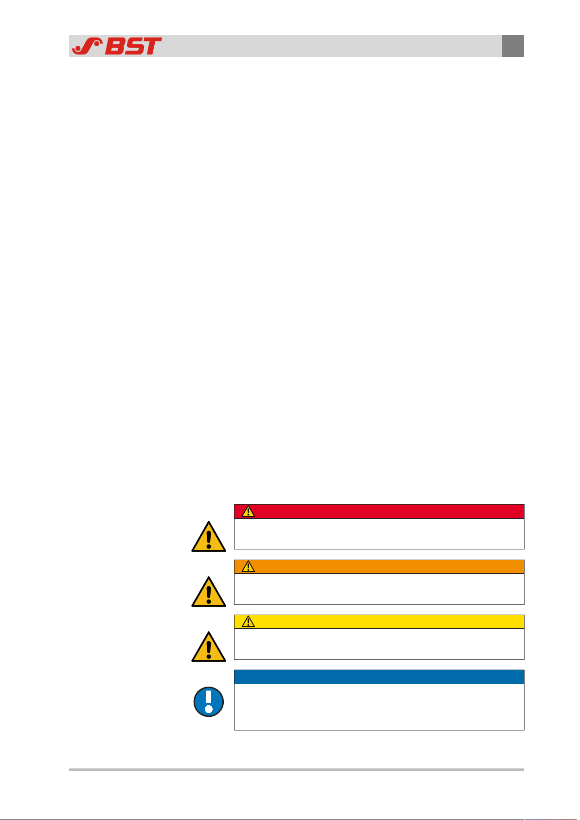
1.4.1 Safety Instructions
DANGER
Danger that will lead to death or severe injuries!
►Here you can find how to avoid the danger.
WARNING
Danger that may lead to death or severe injuries!
►Here you can find how to avoid the danger.
CAUTION
Danger that may lead to medium or minor injuries!
►Here you can find how to avoid the danger.
NOTICE
Danger that may lead to damage to assets!
There is no risk of injury.
►Here you can find how to avoid the danger.

1About This Document
8/220 CLS CAM 100 – Object Sensor
1.4.2 Symbols
Information that is essential for successful operation.
Information that makes operation easier.
Action requirements may include the following symbols:
›› Requirements that must be fulfilled for the action steps.
1. Prompt for you to act. Namely ...
2. ... in the listed sequence.
►Requirement for you to take actions - without any certain se-
quence.
1.4.3 Operation Using Keys
Operations using the keys are indicated by the following symbols:
►Press key ①.
►Press key ① or key ②.
►Press key ① and key ② at the same time.
1.5 More Detailed Information
►Observe the accompanying documents (e.g. order confirma-
tion) for this system and the operating instructions of the en-
tire system.
The latest version of these instructions can be obtained in all
available languages at:
www.bst.help

About Safety 2
CLS CAM 100 – Object Sensor 9/220
2 About Safety
The system has been designed according to the state of the art
and fulfils the latest safety standards.
When using the system, risks may occur that could threaten your
life or health or lead to material damage. In order to avoid these
risks, all instructions in this manual concerning safety and all rel-
evant documentation of the entire system must be observed.
2.1 Intended Use
The system is intended exclusively for the detection of contrast
differences and print features for the control of web-shaped ma-
terials.
The system is installed in a machine or assembled together to
form a machine with another machine in compliance with the Ma-
chinery Directive 2006/42/EC. All machines of the entire system
must comply with the guidelines of the Machinery Directive after
being installed in the system.
The lamps included in the system are special products in accord-
ance with the EU Directive 1194/2012/EC, Art. 2, Paragraph 4. The
lamps are only intended as part of the system for the purpose in-
tended above. Use in other applications is not permitted.
The system and all of its components are only intended for com-
mercial use in an industrial environment.
The system may only be put into operation if the following
guidelines are also complied with:
■The product must only be installed or operated in a non-ex-
plosive atmosphere.
■The product and all components must only be used in a perfect
technical condition.
■All technical safety equipment must be in a perfect technical
condition.
■The product must only be operated using the components that
belong to the system. Excepted from this are such third party
components that have been supplied by BST or have been ex-
plicitly approved for being operated with the system.
■Any part found to be working incorrectly must be replaced im-
mediately using original spare parts.
■All work on or with the product must only be carried out by in-
structed and qualified personnel, see chapter Qualification of
the Personnel, page 14.
■These instructions and all safety information must be observed.
■The operating conditions and performance limits specified in
the technical specifications must be observed.

2About Safety
10/220 CLS CAM 100 – Object Sensor
2.2 Non-intended Use
Every use is non-intended, that is not described in the chapter In-
tended Use or does not comply with the guidelines specified
there, see Intended Use.
2.2.1 Non-intended Infringement of Guidelines
■Infringement of operating, maintaining or installation instruc-
tions
■Unsuitable, incorrect or unauthorized use of the product
■Operating the product in an environment not intended for its
use
■Operating the product in breach of the legal safety guidelines
relevant at the location of use
■Neglecting the warning and safety instructions in the relevant
documents for the product
■Operating the product under faulty safety and protective condi-
tions
2.2.2 Non-intended Operation
■Operation by unauthorized or insufficiently qualified personnel
■By-passing, disassembling, switching off or manipulation of
safety equipment
■Incorrect or negligent handling by the customer
■Any intervention, modification or conversions on the product
without the express approval of BST GmbH
■The use of unsuitable operating materials or spare parts
■Operation of the product near to sources of interference, e.g.
electro-magnetic fields (high voltage lines) or sources of heat
■Operation of the product under the influence of chemical, elec-
tro-chemical or electrical factors
2.2.3 Non-intended modification of electronic data
■No virus scanners, firewalls or similar items may be installed on
any products from BST GmbH. Virus scanners or other scan or
registration programs must not (be able to) access BST
products via networks.
■Writing, deleting and editing of system data / files on BST
products is not permitted. Excepted from this is service work
carried out at the instruction of BST GmbH.
■Access by any external software to BST products via networks is
not permitted.
■USB memory sticks may only be used together with BST
products if they are free of viruses and harmful software.

About Safety 2
CLS CAM 100 – Object Sensor 11/220
■Products or supplied software from BST GmbH must never be
modified without permission.
■All software developed by BST GmbH is protected by copyright
and must not be edited, copied or made available to third
parties. Exceptions to this require the explicit approval of BST
GmbH.
■Other software supplied that has not been developed by BST
GmbH is subject to the licence agreement of the respective
manufacturer.
2.3 Safety Instructions
Every user must read and follow the safety instructions in these
instructions before working with or on the system.
The following contains general safety instructions that always
have to be observed. Special safety information that must be ob-
served for certain work will be specified at the start of the re-
spective chapter of these instructions.
2.3.1 General Safety Instructions
DANGER
Danger of death when operated in potentially explosive areas!
►The system must not be installed or operated in potentially ex-
plosive areas.
DANGER
Danger to life due to moving machine components!
Crushing, shearing, scraping, pulling in or impact injuries of body
parts may occur.
►Never reach into the area containing moving rollers or machine
components.
►Do not wear necklaces, scarves or similar near moving rollers/
machine components.
►Never stay within the swivel/movement range of moving ma-
chine components or reach into these areas.
►Prior to set-up/operation of the system, ensure that no persons
are in the operating range of moving machine components.
DANGER
Danger to life due to electrocution!
Fatal injuries due to incomplete shut-down or residual currents.
►If insulation defects or defects on live components occur, imme-
diately shut down the power supply and have the system re-
paired by a qualified electrician.
►Completely switch off the system, disconnect it from the power
supply and wait for ten minutes before carrying out any main-
tenance, repair, cleaning or assembly work.
►Secure the system against being switched on again.

2About Safety
12/220 CLS CAM 100 – Object Sensor
WARNING
Danger of cutting on sharp edges of the material web!
Severe cutting injuries caused by the edges of the moving material
web.
►Never touch the edges of moving material webs.
WARNING
Danger of falling and damage to assets caused by stepping/climb-
ing onto components!
Stepping/climbing onto components (e.g. traverse bars or camera
housing) can lead to life-threatening falling accidents and to the
destruction of the components.
►Never climb or step onto components.
WARNING
Danger to life due to missing Emergency Stop devices!
Severe injuries may occur, if no Emergency Stop device (Emer-
gency Stop button) is installed on the overall machine line. Only an
Emergency Stop device permits an immediate stop of the machine
line in emergencies. It is not permitted to operate the overall ma-
chine line without an Emergency Stop device.
►If one is not already installed, have an Emergency Stop button
and Emergency Stop systems installed by the owner/user/ma-
chine manufacturer prior to using the machine line.
WARNING
Severe injuries due to unfamiliarity with/non-observance of
Emergency Stop devices and safety information!
►Prior to starting work, familiarize yourself with the Emergency
Stop and rescue devices of the overall machine line, e.g. Emer-
gency Stop button.
►Prior to starting work, ensure that all safety regulations and in-
structions are observed.
WARNING
Eye injuries and dazzling from looking directly into the light
source!
Looking directly into the lighting may lead to impaired eyesight and
subsequent accidents.
►Never look directly into the light source when switched on!
►Using suitable measures, make sure that direct eye contact with
the lighting is impossible.
►Switch off the light source and wait ten minutes before carrying
out maintenance, repair, cleaning or installation work.

About Safety 2
CLS CAM 100 – Object Sensor 13/220
WARNING
Danger of burns caused by hot lamps!
Lamps and light units can cause severe burns when touched, as
they become very hot during operation and only cool down gradu-
ally after being switched off.
►Completely switch off the system, disconnect it from the power
supply and wait for ten minutes before carrying out any main-
tenance, repair, cleaning or assembly work.
►Secure the system against being switched on again.
NOTICE
Damage to electronic components caused by ESD (electrostatic
discharge)!
Destruction/loss of capacity of electronic assembly elements
caused by contact with electro-statically charged persons/objects.
►Only open system components at ESD-compliant workplaces
(according to 61340-5-1).
►If there is no ESD-compliant workplace, take ESD protection
measures (according to DIN EN61340-5-1) to discharge electro-
static charges in a controlled manner.
►When returning electronic assembly elements, adhere to DIN
EN 100015 (“Protection of protection of electrostatic-sensitive
devices”).
►To transport electronic components, only use suitably marked,
electrically conductive ESD packaging.
NOTICE
Damage to the touchscreen due to faulty operation!
Use of sharp, strong or coarse objects (e.g. pens, gloves) may dam-
age the surface of the touchscreen.
►Touch the touchscreen only using bare fingers or a special input
pen (touchpen).

2About Safety
14/220 CLS CAM 100 – Object Sensor
2.4 Qualification of the Personnel
The qualifications required by the personnel are defined as fol-
lows:
Instructed personnel have been instructed comprehensively by
the operating company and informed about the following points:
■Tasks assigned
■Possible hazards when carrying out the tasks
■Possible hazards in the event of incorrect conduct
■Measures for avoiding the hazards
Moreover, qualified personnel have sufficient experience or prac-
tice in the safe implementation of the tasks assigned.
Specialists are in addition in the position to deal with the follow-
ing tasks by themselves due to their training, knowledge and ex-
perience as well as knowledge in the relevant regulations:
■Carrying out the tasks assigned to them
■Recognizing possible hazards
■Undertaking appropriate measures for avoiding the hazards
Specialists must only carry out tasks according to their profes-
sional training.
Qualified electricians have in addition an electrical engineering
training according to the applicable guidelines (in Germany,
DINVDE1000-10).
Moreover, all personnel must satisfy all requirements that are de-
rived from the following documentation or directives:
■Operating instructions for the entire system
■National guidelines, laws and applicable guidelines for protect-
ing employees, general safety at workplaces and for accident
prevention

About Safety 2
CLS CAM 100 – Object Sensor 15/220
2.5 Duties of the Operating Company and Personnel
2.5.1 Duties of the Operating Company
The operating company of the entire system is responsible for
safety in the workplace as well as for the information and training
of the personnel. In particular, for the entire life-cycle of the sys-
tem and the entire system, the operating company must ensure
that:
■All relevant legal safety, accident prevention and environ-
mental guidelines are maintained
■All hazards are determined that result from the special operat-
ing conditions at the operating location of the system and from
the construction of the entire system
■All hazards determined are avoided. This means, in particular:
- Constructive prevention of hazards
- Assembly of protection and safety equipment and checking
that these are working properly
- Mounting of warning signs at hazard sites and checking their
correct condition
- Information and training of the personnel for safe conduct,
intended use, safety equipment, prevention of hazards and
conduct in the event of emergencies
- Provision of the necessary personal protective equipment
- Supervision of the personnel with regard to safety-relevant
conduct
■The system is integrated into the safety concept of the entire
system
■The system is stopped immediately if the safety of people or
the environment is endangered or changes occur that could im-
pair the safety
■All employees have read and understood these instructions be-
fore working on or with the system
■Only personnel are assigned that are qualified and trained for
the respective task
■The responsibility of the personnel is determined for the task
to be completed and that the personnel are informed

2About Safety
16/220 CLS CAM 100 – Object Sensor
2.5.2 Duties of the Personnel
Each and every employee is responsible for their own safety. In
particular, each and every employee must abide by the following
instructions:
►Read these instructions completely before working on or with
the system and follow all safety instructions.
►Observe all warning instructions on the system and entire sys-
tem.
►Observe the operating instructions for the entire system and
the separate machines as well as all safety instructions included
in it.
►If required, wear the necessary personal protective equipment.
►Before starting work, check if the safety equipment is intact.
►Stop the system immediately if the safety of people is at risk
and secure against being switched back on unintentionally.
►The system must be visually inspected for any recognizable
damage or problems at least once per shift.
►If sections of these instructions are unclear, inform your super-
visor and ensure for clarification.
2.6 Conduct in the Event of Danger and Accidents
Preventative Measures
Emergency and rescue equipment must be ready for use in every
company. These include, for example, emergency stop buttons,
fire extinguisher, first aid kit and equipment for reporting acci-
dents.
►Always be prepared for emergencies, accidents and fire.
►Familiarize yourself as to where the emergency and rescue
equipment is located and how to use it.
►Keep emergency and rescue equipment at hand and ready for
use.
►Ensure all access routes for rescue vehicles and escape routes
are kept free.
If an emergency is impending or has occurred
1. Press the emergency stop button immediately.
2. Make sure that the system cannot be switched on again.
3. Rescue the persons from the danger zone if your personal
safety is not at risk.
4. Initiate first aid measures.
5. Warn the emergency doctor and / or fire brigade.
6. Inform the responsible person at the operating location.
7. Clear the access route for the emergency vehicles.

About Safety 2
CLS CAM 100 – Object Sensor 17/220
2.7 Personal Protective Equipment
When carrying out certain activities, you have to wear personal
protective equipment in order to avoid accidents and injuries. Per-
sonal protective equipment includes, depending on the activity:
■Protective clothing
■Safety helmet
■Safety shoes
■Safety gloves
■Eye protectors
■Ear protectors
►Observe the safety information in these instructions and the in-
formation signs on the system for personal protective equip-
ment.
2.8 Guarantee and Liability
The warranty terms are specified in the sales documentation.
2.8.1 Disclaimer
BST GmbH is not liable for damage or defects arising from any in-
correct or non-intended use of the product, see Non-intended
Use, page 10.
Liability for defects does also not apply if the fault originates from
one or more of the following causes:
■Catastrophic events and force majeure
■Natural wear
■Incorrect operation of the product resulting from the effect of
connected or neighboring third party devices
■Malfunction of the product due to unsuitable operating re-
sources, spare parts, chemical, electro-chemical or electrical
factors.
■Unsuitable or faulty execution of the maintenance work de-
scribed by the operating company, see Maintenance and Clean-
ing.
2.8.2 Exceptions to the Disclaimer
In the cases listed above BST GmbH shall also not be liable (for
damages) unless:
■The damage results from a willful or grossly negligent breach of
duty on the part of BST GmbH or its legal representatives or vi-
carious agents
■The damage is associated with injury to life, body or health and
results from a willful or grossly negligent breach of duty on the
part of BST GmbH or its legal representatives or vicarious
agents

2About Safety
18/220 CLS CAM 100 – Object Sensor
■The form of damage can usually and typically be insured
against by means of third-party liability insurance taken out by
BST GmbH on reasonable conditions
This applies in particular to claims for damages associated with
fault or negligence occurring before or upon conclusion of the
contract, the infringement of secondary obligations and claims as-
sociated with impermissible actions; this does not affect claims as-
serted in accordance with the German Product Liability Act or
those associated with a guarantee.
Otherwise, the specific terms of license of BST GmbH apply.
2.8.3 License and Liability for Software Supplied
Software supplied that has not been produced by BST GmbH un-
derlies the respective liability and license agreements of the man-
ufacturer.

Design and function 3
CLS CAM 100 – Object Sensor 19/220
3 Design and function
3.1 Use
The sensor system CLS CAM 100 enables the contact-free posi-
tioning measurement of print features and contrast transitions
(e.g. material edges or printed lines) on running material webs.
In measuring mode, the sensor records the current position (AC-
TUAL position) of a print feature or a contrast transition point on
the material web in automatic mode and then transmits the relev-
ant information to the connected controller.
In automatic mode, the controller compares the ACTUAL meas-
ured position against the default SETPOINT position. A relevant
correction signal will be sent to the guiding device’s actuator if a
deviation is found to exist between the two values. The actuator
will drive the guiding device (rotating frame or swivelling roller
guide) until the material web returns to its SETPOINT position.
Due to the LED lighting integrated in the sensor, the system can
be used more flexibly and, in principle, does not need any external
lighting. Through the projection of a marking line, the laser also in-
stalled in the sensor permits the precise alignment of the system
to the material web.
The following figure shows a typical configuration of the CLS CAM
100 system.
Fig.1: Typical configuration of an CLS CAM 100 system with controller
①CLS CAM 100 sensor ②CLS CAM 100 commander
③ekr 500 digital Unit Touch ④Material web

3Design and function
20/220 CLS CAM 100 – Object Sensor
3.2 Design
A typical design to the web guide control system with a CLS CAM
100 system includes the following components:
■one CLS CAM 100 sensor
■one CLS CAM 100 controller
■one CLS CAM 100 commander
■one BST web guide controller (e.g. ekr 500 digital Unit Touch)
■one guiding device (e.g. pivoting frame guide)
■one set of connecting cables
Fig.2: CLS CAM 100 system components
①Sensor
②Commander
③Controller
3.3 Overview of components
3.3.1 Commander
Fig.3: Front view of the CLS CAM 100 commander
Touchscreen display
During operation, the graphic display ① shows all important in-
formation (live image, print features, edge positions, etc.). The dif-
ferent setup menus of the system are called up and parameter
settings are changed via the touchscreen.
Table of contents
Other BST Accessories manuals


Popular Accessories manuals by other brands

VARSITY Scoreboards
VARSITY Scoreboards VSBX-630LED Operation instructions

Shure
Shure MVI user guide

OHM ELECTRIC
OHM ELECTRIC Cool Cabi OCA-S350BCD-A200 instruction manual

Lennox Hearth Products
Lennox Hearth Products Elite E260 installation instructions

Baumer
Baumer FVDK 10P66ZR manual

Aromateca
Aromateca Harmony user manual


