BST CCD CAM 100 User manual

Web Guiding System
Installation and
Operating Manual
CCD CAM 100
MD.465.EN.06/1.4.x
Translation of the Original Manual

BST GmbH
Remusweg 1
D-33729 Bielefeld
Tel.: +49 (0) 521 400 70 0
Fax: +49 (0) 5206 999 999
E-Mail: [email protected]
Internet: www.bst.group
This documentation is protected by copyright. The translation as well as reproduction and distribution in any form is forbidden without the approval
of the rights holder and will be pursued under civil and criminal law. Technical modifications reserved.

Table of Contents
CCD CAM 100 – Installation and Operating Manual iii
Table of Contents
1 About This Document........................................................................................ 7
1.1 What You Need to Know............................................................................................... 7
1.2 Target Group................................................................................................................. 7
1.3 Storage and Distribution............................................................................................... 7
1.4 Meanings of the Safety Instructions and Symbols........................................................ 7
1.4.1 Safety Instructions ........................................................................................................ 7
1.4.2 Symbols......................................................................................................................... 8
1.5 More Detailed Information........................................................................................... 8
2 About Safety ..................................................................................................... 9
2.1 Intended Use................................................................................................................. 9
2.2 Non-intended Use....................................................................................................... 10
2.2.1 Non-intended Infringement of Guidelines.................................................................. 10
2.2.2 Non-intended Operation............................................................................................. 10
2.2.3 Non-intended Modification of Electronic Data........................................................... 11
2.3 Safety Instructions ...................................................................................................... 12
2.3.1 General Safety Instructions......................................................................................... 12
2.4 Qualification of the Personnel .................................................................................... 15
2.5 Duties of the Operating Company and Personnel ...................................................... 16
2.5.1 Duties of the Operating Company .............................................................................. 16
2.5.2 Duties of the Personnel............................................................................................... 17
2.6 Conduct in the Event of Danger and Accidents .......................................................... 17
2.7 Personal Protective Equipment .................................................................................. 18
2.8 Guarantee and Liability............................................................................................... 18
2.8.1 Disclaimer ................................................................................................................... 18
2.8.2 Exceptions to the Disclaimer....................................................................................... 19
2.8.3 License and Liability for Software Supplied ................................................................ 19
3 Design and Function.........................................................................................20
3.1 Utilization.................................................................................................................... 20
3.2 Design ......................................................................................................................... 22
3.3 Overview of Components ........................................................................................... 23
3.4 Scanning Methods ...................................................................................................... 24
3.5 Function ...................................................................................................................... 26
3.6 Measuring Range ........................................................................................................ 27
3.7 Control and Display Elements..................................................................................... 28
3.7.1 Touchscreen Display ................................................................................................... 29
3.7.2 Service LEDs ................................................................................................................ 30
3.7.3 Service Interface ......................................................................................................... 31
3.7.4 Memory Card Slot....................................................................................................... 31
3.7.5 DIL Switch.................................................................................................................... 32
3.8 Accessories.................................................................................................................. 32
3.9 Name Plate.................................................................................................................. 33
4 Technical Specifications ...................................................................................34
5 Transport, Delivery and Storage.......................................................................39
5.1 Transport..................................................................................................................... 39
5.2 Scope of Delivery ........................................................................................................ 39
5.3 Unpacking the Delivery............................................................................................... 39
5.4 Storage........................................................................................................................ 39
6 Installation.......................................................................................................40
6.1 Safety Instructions ...................................................................................................... 40
6.2 Selecting the Installation Location.............................................................................. 42
6.3 Space Requirement..................................................................................................... 43
6.4 Requirements for an Optimum Measurement Result ................................................ 44

Table of Contents
iv CCD CAM 100 – Installation and Operating Manual
6.5 Mounting Bracket ....................................................................................................... 44
6.5.1 Fixing the CCD Camera on the Mounting Bracket....................................................... 45
6.5.2 Attachment Alternatives............................................................................................. 46
6.5.3 Fixing Dimensions ....................................................................................................... 48
6.6 Measuring Range and Measuring Distance................................................................. 50
6.6.1 Determining the Measuring Range............................................................................. 50
6.6.2 Determining the Measuring Distance ......................................................................... 52
6.7 Mounting the CCD Camera ......................................................................................... 54
6.8 Mounting Supporting Rollers...................................................................................... 55
6.9 Mounting the Light Box............................................................................................... 56
6.9.1 Dimensioning the Light Box ........................................................................................ 56
6.9.2 Mounting the Light Box............................................................................................... 57
7 Electrical Connection........................................................................................58
7.1 Safety Instructions ...................................................................................................... 58
7.2 Cable Routing.............................................................................................................. 59
7.3 Connections ................................................................................................................ 60
7.3.1 Overview..................................................................................................................... 60
7.3.2 X30 - Ethernet ............................................................................................................. 61
7.3.3 X70 - External Illumination.......................................................................................... 62
7.3.4 X80 - Digital Inputs / Outputs...................................................................................... 63
7.3.5 X100 - CAN Bus (Plug) ................................................................................................. 64
7.3.6 X101 - CAN Bus (Socket).............................................................................................. 65
7.4 Establishing the Cable Connections ............................................................................ 66
7.4.1 Standard Application................................................................................................... 66
7.4.2 Special Applications .................................................................................................... 66
7.5 Connecting the Light Box ............................................................................................ 67
7.5.1 Light Box Types ........................................................................................................... 67
7.5.2 Operation on External Power Supply.......................................................................... 68
7.5.3 Operation on CCD CAM 100........................................................................................ 69
8 Commissioning.................................................................................................71
8.1 Safety Instructions ...................................................................................................... 71
8.2 Requirements.............................................................................................................. 72
8.3 Setting the DIL Switches.............................................................................................. 72
8.3.1 DIL Switch Overview ................................................................................................... 72
8.3.2 Setting DIL Switch S1................................................................................................... 74
8.4 Camera Setup Menu ................................................................................................... 75
8.4.1 Quick Setup and Normal Setup................................................................................... 75
8.4.2 Menu Structure........................................................................................................... 76
8.4.3 Setup Wizard............................................................................................................... 77
8.5 Loading the Default Settings....................................................................................... 79
8.6 Setting the Screen Display, Scan Direction and Calibration Method .......................... 80
8.6.1 Rotating the Screen Display........................................................................................ 80
8.6.2 Defining the Scan Direction ........................................................................................ 81
8.6.3 Selecting the Calibration Method ............................................................................... 82
8.7 Defining the Network Settings.................................................................................... 83
8.7.1 Operation on the CAN Bus.......................................................................................... 83
8.7.2 Operation in the Ethernet Network............................................................................ 84
8.8 Checking the Mounting Position of the CCD Camera.................................................. 85
8.8.1 Checking the Alignment to the Web Centerline ......................................................... 85
8.8.2 Checking the Perpendicular Alignment (only with horizontal web running direction)...86
8.9 CCD Camera Alignment............................................................................................... 87
8.9.1 Aligning Steps.............................................................................................................. 87
8.9.2 Goal of the Alignment................................................................................................. 88
8.9.3 Tools and Auxiliary Equipment ................................................................................... 88
8.9.4 Preparation Measures ................................................................................................ 89
8.9.5 Calling Up the Alignment Menu.................................................................................. 91
8.9.6 X Axis Alignment ......................................................................................................... 93

Table of Contents
CCD CAM 100 – Installation and Operating Manual v
8.9.7 Y Axis Alignment ......................................................................................................... 94
8.9.8 Measuring Range Setting............................................................................................ 95
8.9.9 Focus Setting............................................................................................................... 96
8.9.10 Z Axis Alignment.......................................................................................................... 98
8.10 Setting the Aperture ................................................................................................. 102
8.11 Carrying Out White Balance...................................................................................... 103
8.12 Carrying Out Scaling.................................................................................................. 104
8.13 Calibrating the CCD Camera...................................................................................... 107
8.13.1 Calibration Template ................................................................................................ 107
8.13.2 Inserting the Calibration Template ........................................................................... 108
8.13.3 Calibrating the CCD Camera...................................................................................... 109
8.14 Performing a Material Thickness Compensation ...................................................... 110
9 Operation ......................................................................................................112
9.1 Safety Instructions .................................................................................................... 112
9.2 Starting the System................................................................................................... 113
9.3 Opening the Service Opening ................................................................................... 114
9.4 Inserting/Removing the Memory Card ..................................................................... 115
9.5 Menu Navigation ...................................................................................................... 116
9.5.1 Menu Structure......................................................................................................... 116
9.5.2 Path Details............................................................................................................... 116
9.5.3 Opening a Menu ....................................................................................................... 117
9.6 Operation Display ..................................................................................................... 119
9.6.1 Overview................................................................................................................... 119
9.6.2 Display of CAN Bus Information................................................................................ 120
9.6.3 Display of the Data Transfer Rate ............................................................................. 121
9.6.4 Display of the Operating Mode and Sensor Resolution............................................ 121
9.6.5 Error Display.............................................................................................................. 121
9.6.6 Display of the Exposure Settings............................................................................... 121
9.6.7 Display of the Set Aperture Value............................................................................. 122
9.6.8 Display of the Unit for the Output of the Measured Values..................................... 122
9.6.9 Calling Up the System Menus ................................................................................... 122
9.6.10 Display of the Video Curve........................................................................................ 123
9.7 Camera Setup Menu ................................................................................................. 123
9.8 Application Settings Menu........................................................................................ 124
9.8.1 Menu Structure......................................................................................................... 125
9.8.2 Setting the Aperture, Focus and Exposure Time....................................................... 126
9.8.3 Defining the Exposure Settings ................................................................................. 129
9.8.4 Setting the Measuring Range and Focus................................................................... 133
9.8.5 Defining the Edges .................................................................................................... 134
9.8.6 Defining the Edge Detection Area............................................................................. 140
9.8.7 Defining the Edge Detection Sensitivity.................................................................... 143
9.8.8 Defining the Scan Direction ...................................................................................... 145
9.8.9 Setting the Material Distance ................................................................................... 148
9.8.10 Adjusting the Material Thickness.............................................................................. 148
9.8.11 Carrying Out White Balance...................................................................................... 149
9.9 Device Settings Menu ............................................................................................... 149
9.9.1 Menu Structure......................................................................................................... 150
9.9.2 Setting the IP Address............................................................................................... 151
9.9.3 Setting the Netmask ................................................................................................. 151
9.9.4 Showing the MAC Address........................................................................................ 152
9.9.5 Selecting the Synchronization Method..................................................................... 152
9.9.6 Setting the CAN Bus Address .................................................................................... 153
9.9.7 Activating the CAN Bus Terminating Resistor ........................................................... 155
9.9.8 Selecting the Calibration Method ............................................................................. 156
9.9.9 Setting the Calibration Constant............................................................................... 157
9.9.10 Setting the Distance of the CCD Camera to the Material ......................................... 157
9.9.11 Rotating the Screen Display...................................................................................... 158
9.9.12 Locking the Touchscreen .......................................................................................... 159

Table of Contents
vi CCD CAM 100 – Installation and Operating Manual
9.9.13 Restoring the Factory Default Settings ..................................................................... 161
9.9.14 Calibrating the Touchscreen ..................................................................................... 164
9.9.15 Calibrating the Electronic Spirit-Level....................................................................... 166
9.9.16 Storing Camera Parameters on Memory Card.......................................................... 167
9.9.17 Loading Camera Parameters from Memory Card..................................................... 168
9.9.18 Loading a New FPGA File........................................................................................... 169
9.9.19 Selecting the FPGA Mode ......................................................................................... 170
9.9.20 Setting the Sensor Resolution................................................................................... 171
9.9.21 Defining the Scaling Factor for the Measuring Value Output ................................... 172
9.10 System Information Menu ........................................................................................ 173
9.10.1 Menu Structure......................................................................................................... 173
9.10.2 Displaying the Firmware Version .............................................................................. 174
9.10.3 Displaying Service Information ................................................................................. 174
9.10.4 Displaying Information for the Edges 1 - 4................................................................ 175
9.10.5 Displaying Information for the Edges 5 - 8................................................................ 179
9.10.6 Displaying the Measured Values of the Electronic Spirit-Level................................. 180
10 Maintenance and Cleaning.............................................................................181
10.1 Safety Instructions .................................................................................................... 181
10.2 Maintenance Table ................................................................................................... 182
10.3 Maintenance and Cleaning work .............................................................................. 182
10.3.1 Cleaning the Housing ................................................................................................ 182
10.3.2 Cleaning the Protective Filter.................................................................................... 183
10.3.3 Cleaning the Camera Lens......................................................................................... 183
10.3.4 Cleaning the Touchscreen Display ............................................................................ 183
10.3.5 Cleaning the Light Box............................................................................................... 184
11 Accessories and Spare Parts ...........................................................................185
11.1 Order Address........................................................................................................... 185
11.2 Accessories................................................................................................................ 185
11.2.1 Mounting Accessories............................................................................................... 185
11.2.2 Connecting Cables..................................................................................................... 185
11.2.3 Calibration Template ................................................................................................ 185
11.2.4 Light Boxes................................................................................................................ 186
12 Customer Services..........................................................................................192
13 Shutting Down and Disposal...........................................................................193
Index..............................................................................................................194

About This Document 1
CCD CAM 100 – Installation and Operating Manual 7/198
1 About This Document
1.1 What You Need to Know
These instructions help you to work with the system in a safe,
simple and successful manner.
The following instructions must be observed in order to avoid
hazards and incorrect operation:
■Every user must have read these instructions in full before
working with or on the system.
■Every user must follow the safety information in these instruc-
tions.
1.2 Target Group
These instructions are directed to all persons that work with or on
the system. The operating company of the entire system and
supervising personnel must also be familiar with these instructions.
1.3 Storage and Distribution
These instructions must be stored at the workplace in such a
manner that the user has access to them at all times.
These instructions and all other applicable documents are a com-
ponent of the product and must be handed over to the operating
company of the system.
1.4 Meanings of the Safety Instructions and Symbols
1.4.1 Safety Instructions
DANGER
Danger that will lead to death or severe injuries!
►Here you can find how to avoid the danger.
WARNING
Danger that may lead to death or severe injuries!
►Here you can find how to avoid the danger.
CAUTION
Danger that may lead to medium or minor injuries!
►Here you can find how to avoid the danger.
NOTICE
Danger that may lead to damage to assets!
There is no risk of injury.
►Here you can find how to avoid the danger.

1About This Document
8/198 CCD CAM 100 – Installation and Operating Manual
1.4.2 Symbols
Information that is essential for successful operation.
Information that makes operation easier.
Action requirements may include the following symbols:
›› Requirements that must be fulfilled for the action steps.
1. Prompt for you to act. Namely ...
2. ... in the listed sequence.
►Requirement for you to take actions - without any certain
sequence.
1.5 More Detailed Information
►Observe the accompanying documents (e.g. order confirmation)
for this system and the operating instructions of the entire sys-
tem.
The latest version of these instructions can be obtained in all
available languages at:
https://www.bst.help

About Safety 2
CCD CAM 100 – Installation and Operating Manual 9/198
2 About Safety
The system has been designed according to the state of the art
and fulfils the latest safety standards.
When using the system, risks may occur that could threaten your
life or health or lead to material damage. In order to avoid these
risks, all instructions in this manual concerning safety and all
relevant documentation of the entire system must be observed.
2.1 Intended Use
The CCD camera is only intended for the detection of contrast
differences for the guiding of web-shaped materials and for the
web width measurement.
The system is integrated in a machine or connected with another
machine to form a machine as defined by machinery directive
2006/42/EC. All machines and the overall machine line must meet
the requirements of the machinery directive after integration of
the system.
The lamps included in this system are special products in accord-
ance with the EU Directive 1194/2012/EC, Art. 2, Paragraph 4. The
lamps are only intended for use as specified above as part of this
system. Any use other than as intended as is not permitted.
The system and all of its components are exclusively intended for
commercial use in an industrial environment.
Moreover, the system may only be started up, if the following
regulations are adhered to:
■The product must only be installed or operated in a non-
explosive atmosphere.
■The product and all components may only be used while in
perfect condition.
■All safety devices must be in perfect condition.
■The product may only be operated with the components
belonging to the system. The only third-party components
exempt from the above are those supplied by BST or explicitly
approved for use with the system.
■Parts that are not in perfect condition must immediately be
replaced with original spare parts.
■All work on or with the product may only be performed by
instructed and qualified personnel, see chapter Qualification of
the Personnel, page 15.
■Always adhere to this operating manual and all safety instruc-
tions.
■The operating conditions and performance limits indicated in
the technical data must be observed.

2About Safety
10/198 CCD CAM 100 – Installation and Operating Manual
2.2 Non-intended Use
Every use is non-intended, that is not described in the chapter
Intended Use or does not comply with the guidelines specified
there, see Intended Use, page 9.
2.2.1 Non-intended Infringement of Guidelines
■Infringement of operating, maintaining or installation instructions
■Unsuitable, incorrect or unauthorized use of the product
■Operating the product in an environment not intended for its
use
■Operating the product in breach of the legal safety guidelines
relevant at the location of use
■Neglecting the warning and safety instructions in the relevant
documents for the product
■Operating the product under faulty safety and protective condi-
tions
2.2.2 Non-intended Operation
■Operation by unauthorized or insufficiently qualified personnel
■By-passing, disassembling, switching off or manipulation of
safety equipment
■Incorrect or negligent handling by the customer
■Any intervention, modification or conversions on the product
without the express approval of BST GmbH
■The use of unsuitable operating materials or spare parts
■Operation of the product near to sources of interference, e.g.
electro-magnetic fields (high voltage lines) or sources of heat
■Operation of the product under the influence of chemical,
electro-chemical or electrical factors

About Safety 2
CCD CAM 100 – Installation and Operating Manual 11/198
2.2.3 Non-intended Modification of Electronic Data
■No virus scanners, firewalls or similar items may be installed on
any products of BST GmbH. Virus scanners or other scan or
registration programs must not (be able to) access products via
networks.
■Writing, deleting and editing of system data / files on BST
products is not permitted. Exempt from this is service work
carried out at the instruction of BST GmbH.
■Access of any external software to BST products via networks is
not permitted.
■USB memory sticks may only be used together with BST
products if they are free of viruses and harmful software.
■Products or supplied software from BST GmbH must never be
modified without permission.
■All software supplied is protected by copyright and must not be
edited, copied or made available to third parties. Except where
explicit approval has been sought from BST GmbH or the
respective owner of the copyright.

2About Safety
12/198 CCD CAM 100 – Installation and Operating Manual
2.3 Safety Instructions
Every user must read and follow the safety instructions in these
instructions before working with or on the system.
The following contains general safety instructions that always
have to be observed. Special safety information that must be
observed for certain work will be specified at the start of the
respective chapter of these instructions.
2.3.1 General Safety Instructions
DANGER
Danger of death when operated in potentially explosive areas!
►The system must not be installed or operated in potentially
explosive areas.
DANGER
Danger to life due to moving machine components!
Crushing, shearing, scraping, pulling in or impact injuries of body
parts may occur.
►Never reach into the area containing moving rollers or machine
components.
►Do not wear necklaces, scarves or similar near moving rollers/
machine components.
►Never stay within the swivel/movement range of moving
machine components or reach into these areas.
►Prior to set-up/operation of the system, ensure that no persons
are in the operating range of moving machine components.
DANGER
Danger to life due to electrocution!
Fatal injuries due to incomplete shut-down or residual currents.
►If insulation defects or defects on live components occur,
immediately shut down the power supply and have the system
repaired by a qualified electrician.
►Completely switch off the system, disconnect it from the power
supply and wait for ten minutes before carrying out any main-
tenance, repair, cleaning or assembly work.
►Secure the system against being switched on again.
WARNING
Danger of cutting on sharp edges of the material web!
Severe cutting injuries caused by the edges of the moving material
web.
►Never touch the edges of moving material webs.
About Safety 2
CCD CAM 100 – Installation and Operating Manual 13/198
WARNING
Danger of falling and damage to assets caused by stepping/climb-
ing onto components!
Stepping/climbing onto components (e.g. traverse bars or camera
housing) can lead to life-threatening falling accidents and to the
destruction of the components.
►Never climb or step onto components.
WARNING
Danger to life due to missing Emergency Stop devices!
Severe injuries may occur, if no Emergency Stop device (Emer-
gency Stop button) is installed on the overall machine line. Only an
Emergency Stop device permits an immediate stop of the machine
line in emergencies. It is not permitted to operate the overall ma-
chine line without an Emergency Stop device.
►If one is not already installed, have an Emergency Stop button
and Emergency Stop systems installed by the owner/user/
machine manufacturer prior to using the machine line.
WARNING
Severe injuries due to unfamiliarity with/non-observance of
Emergency Stop devices and safety information!
►Prior to starting work, familiarize yourself with the Emergency
Stop and rescue devices of the overall machine line, e.g. Emer-
gency Stop button.
►Prior to starting work, ensure that all safety regulations and
instructions are observed.
WARNING
Eye injuries and dazzling from looking directly into the light source!
Looking directly into the lighting may lead to impaired eyesight and
subsequent accidents.
►Never look directly into the light source when switched on!
►Using suitable measures, make sure that direct eye contact with
the lighting is impossible.
►Switch off the light source and wait ten minutes before carrying
out maintenance, repair, cleaning or installation work.
WARNING
Danger of burns caused by hot lamps!
Lamps and light units can cause severe burns when touched, as
they become very hot during operation and only cool down gradu-
ally after being switched off.
►Completely switch off the system, disconnect it from the power
supply and wait for ten minutes before carrying out any main-
tenance, repair, cleaning or assembly work.
►Secure the system against being switched on again.

2About Safety
14/198 CCD CAM 100 – Installation and Operating Manual
NOTICE
Damage to electronic components caused by ESD (electrostatic
discharge)!
Destruction/loss of capacity of electronic assembly elements
caused by contact with electro-statically charged persons/objects.
►Only open system components at ESD-compliant workplaces
(according to 61340-5-1).
►If there is no ESD-compliant workplace, take ESD protection
measures (according to DIN EN61340-5-1) to discharge electro-
static charges in a controlled manner.
►When returning electronic assembly elements, adhere to DIN
EN 100015 (“Protection of protection of electrostatic-sensitive
devices”).
►To transport electronic components, only use suitably marked,
electrically conductive ESD packaging.
NOTICE
Damage to the touchscreen due to faulty operation!
Use of sharp, strong or coarse objects (e.g. pens, gloves) may dam-
age the surface of the touchscreen.
►Touch the touchscreen only using bare fingers or a special input
pen (touchpen).

About Safety 2
CCD CAM 100 – Installation and Operating Manual 15/198
2.4 Qualification of the Personnel
The qualifications required by the personnel are defined as follows:
Instructed personnel have been instructed comprehensively by
the operating company and informed about the following points:
■Tasks assigned
■Possible hazards when carrying out the tasks
■Possible hazards in the event of incorrect conduct
■Measures for avoiding the hazards
Moreover, qualified personnel have sufficient experience or
practice in the safe implementation of the tasks assigned.
Specialists are in addition in the position to deal with the follow-
ing tasks by themselves due to their training, knowledge and ex-
perience as well as knowledge in the relevant regulations:
■Carrying out the tasks assigned to them
■Recognizing possible hazards
■Undertaking appropriate measures for avoiding the hazards
Specialists must only carry out tasks according to their profes-
sional training.
Qualified electricians have in addition an electrical engineering
training according to the applicable guidelines (in Germany,
DINVDE1000-10).
Moreover, all personnel must satisfy all requirements that are
derived from the following documentation or directives:
■Operating instructions for the entire system
■National guidelines, laws and applicable guidelines for protecting
employees, general safety at workplaces and for accident pre-
vention

2About Safety
16/198 CCD CAM 100 – Installation and Operating Manual
2.5 Duties of the Operating Company and Personnel
2.5.1 Duties of the Operating Company
The operating company of the entire system is responsible for
safety in the workplace as well as for the information and training
of the personnel. In particular, for the entire life-cycle of the system
and the entire system, the operating company must ensure that:
■All relevant legal safety, accident prevention and environ-
mental guidelines are maintained
■All hazards are determined that result from the special operating
conditions at the operating location of the system and from the
construction of the entire system
■All hazards determined are avoided. This means, in particular:
- Constructive prevention of hazards
- Assembly of protection and safety equipment and checking
that these are working properly
- Mounting of warning signs at hazard sites and checking their
correct condition
- Information and training of the personnel for safe conduct,
intended use, safety equipment, prevention of hazards and
conduct in the event of emergencies
- Provision of the necessary personal protective equipment
- Supervision of the personnel with regard to safety-relevant
conduct
■The system is integrated into the safety concept of the entire
system
■The system is stopped immediately if the safety of people or
the environment is endangered or changes occur that could
impair the safety
■All employees have read and understood these instructions
before working on or with the system
■Only personnel are assigned that are qualified and trained for
the respective task
■The responsibility of the personnel is determined for the task
to be completed and that the personnel are informed

About Safety 2
CCD CAM 100 – Installation and Operating Manual 17/198
2.5.2 Duties of the Personnel
Each and every employee is responsible for their own safety. In
particular, each and every employee must abide by the following
instructions:
►Read these instructions completely before working on or with
the system and follow all safety instructions.
►Observe all warning instructions on the system and entire system.
►Observe the operating instructions for the entire system and
the separate machines as well as all safety instructions included
in it.
►If required, wear the necessary personal protective equipment.
►Before starting work, check if the safety equipment is intact.
►Stop the system immediately if the safety of people is at risk
and secure against being switched back on unintentionally.
►The system must be visually inspected for any recognizable
damage or problems at least once per shift.
►If sections of these instructions are unclear, inform your super-
visor and ensure for clarification.
2.6 Conduct in the Event of Danger and Accidents
Preventative Measures
Emergency and rescue equipment must be ready for use in every
company. These include, for example, emergency stop buttons,
fire extinguisher, first aid kit and equipment for reporting acci-
dents.
►Always be prepared for emergencies, accidents and fire.
►Familiarize yourself as to where the emergency and rescue
equipment is located and how to use it.
►Keep emergency and rescue equipment at hand and ready for
use.
►Ensure all access routes for rescue vehicles and escape routes
are kept free.
If an emergency is impending or has occurred
1. Press the emergency stop button immediately.
2. Make sure that the system cannot be switched on again.
3. Rescue the persons from the danger zone if your personal
safety is not at risk.
4. Initiate first aid measures.
5. Warn the emergency doctor and / or fire brigade.
6. Inform the responsible person at the operating location.
7. Clear the access route for the emergency vehicles.

2About Safety
18/198 CCD CAM 100 – Installation and Operating Manual
2.7 Personal Protective Equipment
When carrying out certain activities, you have to wear personal
protective equipment in order to avoid accidents and injuries.
Personal protective equipment includes, depending on the activity:
■Protective clothing
■Safety helmet
■Safety shoes
■Safety gloves
■Eye protectors
■Ear protectors
►Observe the safety information in these instructions and the in-
formation signs on the system for personal protective equip-
ment.
2.8 Guarantee and Liability
The warranty terms are specified in the sales documentation.
2.8.1 Disclaimer
BST GmbH is not liable for damage or defects arising from any
incorrect or non-intended use of the product, see Non-intended
Use, page 10.
Liability for defects does also not apply if the fault originates from
one or more of the following causes:
■Catastrophic events and force majeure
■Natural wear
■Incorrect operation of the product resulting from the effect of
connected or neighboring third party devices
■Malfunction of the product due to unsuitable operating
resources, spare parts, chemical, electro-chemical or electrical
factors.
■Unsuitable or faulty execution of the maintenance work
described by the operating company, see Maintenance and
Cleaning, page 181.

About Safety 2
CCD CAM 100 – Installation and Operating Manual 19/198
2.8.2 Exceptions to the Disclaimer
In the cases listed above BST GmbH shall also not be liable (for
damages) unless:
■The damage results from a willful or grossly negligent breach of
duty on the part of BST GmbH or its legal representatives or
vicarious agents
■The damage is associated with injury to life, body or health and
results from a willful or grossly negligent breach of duty on the
part of BST GmbH or its legal representatives or vicarious agents
■The form of damage can usually and typically be insured
against by means of third-party liability insurance taken out by
BST GmbH on reasonable conditions
This applies in particular to claims for damages associated with
fault or negligence occurring before or upon conclusion of the
contract, the infringement of secondary obligations and claims
associated with impermissible actions; this does not affect claims
asserted in accordance with the German Product Liability Act or
those associated with a guarantee.
Otherwise, the specific terms of license of BST GmbH apply.
2.8.3 License and Liability for Software Supplied
Software supplied that has not been produced by BST GmbH
underlies the respective liability and license agreements of the
manufacturer.
3Design and Function
20/198 CCD CAM 100 – Installation and Operating Manual
3 Design and Function
3.1 Utilization
The CCD camera CCD CAM100 permits the contact-free position
measurement of contrast transitions (e.g. material edges) on the
running material webs. Their standard application area is for
■Web edge guiding
■Web center-line guiding
■Web width measurement
Depending on the web width, the desired measuring accuracy
(resolution) and the application case, one or two CCD cameras are
used.
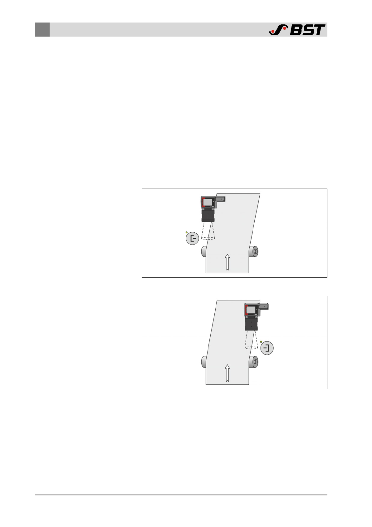
Single camera system
CAN Address = 21
Left
edge
Fig.1: Guiding to the left web edge
CAN Address = 21
Right
edge
Fig.2: Guiding to the right web edge
Table of contents
Other BST Accessories manuals


Popular Accessories manuals by other brands


ROSE DISPLAYS
ROSE DISPLAYS ANOQUICK SQUARE WITH GOTCHA AND MULTICLIPS manual

Apera Instruments
Apera Instruments LabSen 853-S user manual

Helios
Helios KWL-CO2 operating instructions

PolyVision
PolyVision CopyCam installation guide

Sterilize+
Sterilize+ UV Sanitizing Wand quick start guide

Apogee
Apogee SQ-420 owner's manual


