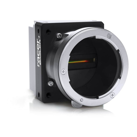
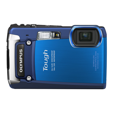
BST eltromat CCDPro 30000 Operational manual

CCD Camera EDV-No.: MD.167.01.07/2.6.8
CCDPro 30000/5000 Issued: 30.03.2011
BST-eltromat CCD Camera
CCDPro 30000/5000
Translation of the Original
Operating Manual
BST eltromat International GmbH
Heidsieker Heide 53
33739 Bielefeld, Germany
Tel: +49 (0) 5206/999 – 0
Fax: +49 (0) 5206/999 – 999
Email: info@bst-international.com

CCD Camera EDV-No.:MD.167.01.07/2.6.8
CCDPro 30000/5000 Date: 30.03.2011
Symbols used in this operating manual
Warning signs
Symbols are used in this operating manual in order to clearly
indicate particularly important places.
Attention!
You must obey this type of warning, in order to protect
yourself, as the operator, from bodily injuries arising
from mechanical movements.
Beware!
You must obey by this type of warning without fail, in
order to protect yourself, as the operator, from life
threatening injuries caused by electrical voltages.
Note
This symbol is used to point out additional useful tips,
which will help you to make optimum use of all of the
functions.
!

Contents
CCD Camera EDV-No.:MD.167.01.07/2.6.8 Chapter:
CCDPro 30000/5000: Date: 30.03.2011 Page: 1/1
Contents
Table of contents
1 Description
1.1 General information: 1-2
1.2 Utilisation 1-2
1.3 Safety information 2-2
1.4 Emissions 2-2
2 Display and operating controls
2.1 Camera control panel 1-2
2.2 Connections 2-2
3 Menus
3.1 Entering the numerical values 1-6
3.2 Foot line menu 2-6
3.3 Set-up menu 5-6
4 Assembly / Installation
4.1 Installation site requirements 1-3
4.2 Installing the camera 1-3
4.3 Installing the light source 1-3
4.4 Background determination 2-3
4.5 Fitting a support roller 2-3
4.6 Installation 3-3
5 Commissioning
5.1 Camera settings 1-18
5.2 Mechanical alignment 3-18
5.3 Camera configuration 11-18
5.4 Programming the camera for asynchronous
operation PDO transfer 18-18
6 Operation
6.1 General information 1-4
6.2 Changing the settings during operation 2-4
7 Maintenance 1-1
8 Specifications 1-2
9 Transport 1-1
10 Decommissioning 1-1
Appendix
Annex 1 CCD Pro 28 mm lens measuring distances
Annex 2 CCD Pro 50 mm lens measuring distances

Description 1
CCD Camera EDV-No.: MD.167.01.07/2.6.8 Chapter: 1.0
CCDPro 30000/5000 Date: 30.03.2011 Page: 1/2
1. Description
General information
This operating manual covers all CCDPro … model CCD-
cameras.
It describes the standard web guiding application using one or two
cameras and the width measurement application used with a
running material web.
The camera is fitted with an RGB-chip and this enables it to
evaluate the three basic colours. This ensures safe recognition as
well as reliable system operation.
The camera parameters can be stored externally in the machine
controller or PC, etc., thus ensuring that they are always available
for any repeat jobs that might occur later on.
Optimisation of the camera parameters as a result of alterations
made to the material parameters can be implemented during
ongoing operation (as necessary). This means that downtime is no
longer required if such a case occurs.
1.2 Utilisation
The CCDPro … CCD-camera has been designed for use as a non-
contact positional measurement system. It determines the position
from the contrast generated by edges, lines, grooves etc., in and on
the running material.
The camera can scan in both directions.
The measurement results are used to control the material or for
measuring the width of the material. The contrast transition is
recorded, depending on the job definition, using:
a) A transmission light process b) A reflection copy light process
Transmission light process: the light source is seen by the
camera to be behind the material web that is being scanned. Only
the edges of the material can be recorded when non-transparent
materials are being used. You can use one or two cameras to scan
the edges, depending on the job definition.
camera
Position settings for the
contrast transitions
material
0 5000 (30000)

Description 1
CCD Camera EDV-No.: MD.167.01.07/2.6.8 Chapter: 1.0
CCDPro 30000/5000 Date: 30.03.2011 Page: 2/2
!
It is important that both edges must always lie within the visual
range of the camera when using a single camera for width
measurement or web centre control. One edge must lie within each
of the camera’s visual range when using two cameras. This must
be guaranteed if the web position fluctuates.
Reflection copy light process: the light source and the camera
must be positioned on the same side of the material web that has
to be scanned. The camera records the light from the light source
that is reflected from the material web. The reflection copy process
enables lines, grooves, creases, etc., to be recorded as well.
All of the data coming from and going to the camera is transferred
via a CAN-interface.
A keypad with 8 keys and a graphics display is used for executing
the basic operating functions and displaying the web position(s).
1.3 Safety information
The safety relevant information in accordance with DIN EN ISO
13857, EN 349 and the industry specific safety regulations must be
taken into consideration when installing the BST-eltromat
equipment in the production machine, these include:
•There must be a safe distance between the BST-eltromat
equipment and the machinery already installed on-site, such as
machine panels, building structure, etc.
•The interconnecting lines between the control equipment and
the control components or edge sensors must be laid so that
nobody can trip over them, they are not taught and they are well
anchored.
Only trained specialist personnel are permitted
to carry out the assembly, installation and
commissioning!
The mains power must be switched off before the
equipment is opened.
If it becomes necessary to work on the open
equipment with voltage applied, then only Protection
class IP 20 is provided.
There is always increased danger because of the
mains voltage!
1.4 Emissions
The A-evaluated equivalent continuous noise level generated by
the equipment is les than 70 dB(A).

Operating controls 2
CCD Camera EDV-No.: MD.167.01.07/2.6.8 Chapter: 2.0
CCDPro 30000/5000 Date: 30.03.2011 Page: 1/2
2. Display and operating controls
2.1 Camera control panel
Graphics display
The graphics display is used to display the brightness curve, edge
positions, set-up menus, parameters and bus status information.
The scan direction that the camera is scanning is shown beneath
the graphic display. It shows the direction from which the image will
be taken.
Note: However, the camera is positioned to be able to scan in the
opposite direction as well.
This means: That the first pixel in the scan direction displayed
above is pixel 0 and the last pixel in this direction is
pixel 4999 (CCDPro 5000) or pixel 29999 (CCDPro
30000).
Keypad
The camera can be aligned for operation using this keypad.
Key Function
Call up set-up mode
Save the entered setting
Exit set-up mode
The function depends on the selected
menu or the planned operation and is
described in detail in the relevant section.

Operating controls 2
CCD Camera EDV-No.: MD.167.01.07/2.6.8 Chapter: 2.0
CCDPro 30000/5000 Date: 30.03.2011 Page: 2/2
2.2 Connections
24V power supply
PIN assignments: 1 = 24 V
2 = 24 V (internally connected to PIN1)
3 = 0 V
Ethernet 10/100 MB (optional)
CAN-bus connections
CAN-connection PIN assignments
(as seen from the soldered or screw side)
Socket (female) Plug (male)
PIN No. Assignments
1 shield
2 nc
3 ground
4 CAN high
5 CAN low

Menus 3
CCD Camera EDV-No.: MD.167.01.07/2.6.8 Chapter: 3.0
CCDPro 30000/5000 Date: 30.03.2011 Page: 1/6
3. Menus
Two menus are available, one for camera alignment and one for
operating the camera.
3.1. Entering the numerical values
Numerical values must be entered in different places in the menus
(e.g. setting the trigger threshold).
Procedure:
1. Select the required setting, e.g. trigger threshold A.
The value will be displayed “inversely”.
2. Press the “ENTER“ button. An input box will be displayed
on the screen.
The decimal place setting and the length of the input are
set to default settings when the input box is called up and
these cannot be altered.
3. You can now increase or decrease the value
using the arrow keys.
Keep pressing the relevant key to increase or decrease the
value by 1. If a major value change is required, keep the
relevant key pressed down until the required value is
reached.
Pressing the “SET-UP“ key will reset the value to zero.
4. Press the “ENTER“ to import the new value and to exit the
inputting routine.
Press the “ESC“ key if you do not want to import the new
value that you have entered. This will exit the inputting
routine without changing the original setting.

Menus 3
CCD Camera EDV-No.: MD.167.01.07/2.6.8 Chapter: 3.0
CCDPro 30000/5000 Date: 30.03.2011 Page: 2/6
3.2. Foot line menu
This menu is activated when the camera is operating normally. One
line from the menu will be displayed in the bottom line of the
graphic display.
3.2.1 Menu navigation
Use the “Up“ or “Down“ arrows to select the required menu line or
the entries in the sub-menu.
Use the “Right“ or “Left“ arrow keys to select from within the line
displayed on the screen.
Press the “ENTER“ key to confirm the selection.
The relevant sub-menu (if available) will be displayed afterwards.
The menu will be exited automatically after the last sub-menu has
been edited.
Press the “ESC“ key to abort the entry in the set-up menu.
The parameters of the selected edge cannot be fully displayed due
to the display size in the menu bar.
The entries in columns 1 and 2 as well as 16 and 17 are always
displayed. The parameters in columns 3 – 15 shift to the right or
left, according to which parameter is selected with the arrow key.
Example:
Trigger A selected Search mode selected
3.2.2 Menu lines and the edge parameter significances
The first 8 lines display the most important edge parameters for
the 8 edges.
Default values are shown for the first 4 edges and the values for
edges 5 - 8 are freely selectable.

Menus 3
CCD Camera EDV-No.: MD.167.01.07/2.6.8 Chapter: 3.0
CCDPro 30000/5000 Date: 30.03.2011 Page: 3/6
column
line
1 2 3 4 5 6 7 8 9 10 11 12 13 14 15 16 17
1 1 1> A 127 B 125 a 8 b 69 AB
A
12.3
N
2500
VWN
Focus value of the
corresponding edge
2 2 1< A 127 B 125 a 69 b 8 AB
3 3 1< A 125 B 127 a 8 b 69 AB
4 4 1> A 125 B 127 a 69 b 8 AB
5 5
--♦
A 125 B 127 a b
6 6 --
♦
A 125 B 127 a b
7 7 --
♦
A 125 B 127 a b
8 8 --
♦
A 125 B 127 a b
9 edge 1 edge 2 edge 3 edge 4 n = standardised
10 edge 5 edge 6 edge 7 edge 8 n
11 edge 1 edge 2 edge 3 edge 4 p = physically
12 edge 5 edge 6 edge 7 edge 8 p
13 web width left middle between the web centres
- 2500
web width right
The first 8 lines display the most important edge parameters for the
8 edges.
The first 4 edges are assigned default values.
In general, all of the edge definitions are freely selectable.
Column 1: Column 1 displays the edge number.
Column 2: Column 2 contains the edge definition.
The construction of the entry is explained in the following
example:
1>
•The number states how many edges should be
used in the search direction.
•The search direction must be set afterwards.
Search direction to the right = >
Search direction to the left = <.
•The contrast is defined in the third position.
= Contrast dark/bright
= Contrast bright/dark
Columns 3 and 4: Show trigger threshold A and the associated
trigger setting.
Columns 5 and 6: Show trigger threshold B and the associated
trigger setting.
Columns 7 and 8: Show the minimum edge width a and the
corresponding trigger setting.
Columns 9 and 10: Show the minimum edge width b and the
corresponding trigger setting.

Menus 3
CCD Camera EDV-No.: MD.167.01.07/2.6.8 Chapter: 3.0
CCDPro 30000/5000 Date: 30.03.2011 Page: 4/6
Column 11: Defines the increment used for the edge numbers.
The edge entry is possibly on Aor Bor on the
middle value between A and B (AB).
The default setting is AB.
The block entry on A or B is used in specific cases in
order to achieve better recognition (e.g. in the case
of bad splice recognition).
Column 12: Displays the selected exposure mode.
A= Automatic exposure “ON“
F= Automatic exposure “OFF“. The exposure time is
fixed and depends on the setting displayed.
Column 13: Displays the current exposure time in ms.
Column 14: The entry states whether the edge is being searched
from the first pixel of the viewing range (N) or from a
fixed starting position (P).
For standard web guide control, please keep the following in
mind: If option P is selected, the edges must be
reconfigured. The configuration should be applied to the
camera.
Example:
Searching from the first pixel in the visible field (option N)
Searching from a fixed pixel position (option P)
Column 15: The entry states the starting pixel for the edge
search when option Pis selected.
If you enter a value while option N is selected in
column 14, this value will be ignored by the system.
When searching the edge from a fixed starting position
(option P), the beginning of the search can be set in the web
centre. The advantage of this approach lies in the reduced
susceptibility of the system to contamination and thus
provides a more effective measurement.
Column 16: Displays the current curve mode in abbreviated form.
V = video curve
W = white balance curve
VW = video curve with white balance correction
VWN = VW standardised display
Scan direction edge 1 = 1>
Scan direction edge 2 = 1<
Scan direction edge 1 = 1< P 2500
Scan direction edge 2 = 1> P 2500

Menus 3
CCD Camera EDV-No.: MD.167.01.07/2.6.8 Chapter: 3.0
CCDPro 30000/5000 Date: 30.03.2011 Page: 5/6
Lines 9 and 10 show the standardised edge positions.
Lines 11 and 12 show the physical edge positions.
When line 13 is selected, alignment mode is automatically
activated. Displayed here is the width of the left web, the centre of
the web minus half the resolution and the width of the right web.
Attention: Alignment mode interrupts a running control or
web width measurement!
Thus it should never be started during normal
operation.
3.3 Set-up menu
This menu is displayed at the front of the graphics display.
Press the “SET UP“ key to call up this menu.
Other display sections are not updated whilst the “Set-up” menu is
displayed.
3.3.1 Menu navigation
Use the “Up“ or “Down“ arrow keys to select the required menu
option.
The selected entry will be displayed “inversely”.
As the screen window does not display the entire menu, scrolling
will occur as necessary when the respective end has been
reached. The menu displayed in the window will be moved upwards
automatically when scrolling downwards and downwards when
scrolling upwards.
Press the “ENTER“ key to confirm the selection.
The relevant sub-menu (if available) will be displayed afterwards.
The set-up menu will be exited automatically and the operating
screen will be displayed after the last sub-menu has been edited.
Press the “ESC“ key to abort the entry in the set-up menu.

Menus 3
CCD Camera EDV-No.: MD.167.01.07/2.6.8 Chapter: 3.0
CCDPro 30000/5000 Date: 30.03.2011 Page: 6/6
3.3.2 Menu hierarchy
The explanations of the individual menu options are given in the
chapter in which they are used.
Save parameters
Parameters
Remote
Set defaults
Curve mode
White balance
Black balance
● Language
● German
● English
● Curve mode
● dot
● line
● Bus info
● off
● on
● Yes
● No
● Remote off
● Camera x, y
● Camera x, z
● Yes
● No
● Reset communication
● Reset application
● Reset all
● WD
-Test
● Video Abs
● White Abs
● V
∗W Abs
● V ∗W standard
White bal. min. lvl.
Aut. exp. target lvl.

Assembly / Installation 4
CCD Camera EDV-No.: MD.167.01.07/2.6.8 Chapter: 4.0
CCDPro 30000/5000 Date: 30.03.2011 Page: 1/3
4 Assembly / Installation
4.1Installation site requirements
The CCDPro … camera must be installed in a dry,
non-vibrating position.
Ambient conditions: Temperature: 0 to a max. 45°C
Humidity: 5 - 90%,
no condensation
4.2 Installing the camera
A BST-eltromat-holder, which enables you to align the camera to
the material web in three axes, is provided as the camera-
mounting unit.
The installation version depends on the job definition and the site
chosen as the installation site in the production machine.
For example:
4.3 Installing the light source
The installation of the light source depends on the scanning
method that you plan to use.
However, you must bear in mind that a build up of dirt must be
prevented.
The following must also be taken into consideration when using
reflection copy:
•The light source must be installed so that the light beam being
reflected from the surface is reflected into the camera when
scanning the edges of transparent material.
For example:
Material web
Material background
camera
Light source

Assembly / Installation 4
CCD Camera EDV-No.: MD.167.01.07/2.6.8 Chapter: 4.0
CCDPro 30000/5000 Date: 30.03.2011 Page: 2/3
•The light source should be aligned so that diffuse reflection is
produced for recognising lines and colour contrasts on
transparent and non-transparent material webs. This is
dependent on the type of light source being used and the
material that is being scanned.
For example:
You must ensure without fail that the light source is never
positioned in the camera’s visual path when working with reflection
copy.
4.4 Background determination
If necessary, a matt black material background plate must be
installed behind the material web so that it is always in the
camera’s visual area. This will prevent ambient light from having
any effect and thus guarantee correct scanning of the edge of the
material web.
4.5 Fitting a support roller
You must ensure that the material web is never creased nor
becomes wavy as both of these problems will affect the edges.
You must also prevent any height fluctuations from occurring with
regard to the material web, as these will have a detrimental affect
on the measured results.
These problems can be eliminated by fitting a support roller.
Material background
Material web
Light source
camera

Assembly / Installation 4
CCD Camera EDV-No.: MD.167.01.07/2.6.8 Chapter: 4.0
CCDPro 30000/5000 Date: 30.03.2011 Page: 3/3
4.6 Installation
Connect up the electrical supplies as shown in the connection
diagram.
The CAN-bus lines must be screened and must be laid separately
from any other lines that might interfere with them or those carrying
high power.
You must ensure that and that the lines are connected up correctly,
are protected and that the insulation is not damaged.
You are only permitted to use HF-fluorescent lamps (≥30 kHz) as
the light source.

Commissioning 5
CCD Camera EDV-No.:MD.167.01.07/2.6.8 Chapter: 5.0
CCDPro 30000/5000 Date: 30.03.2011 Page: 1/18
5. Commissioning
5.1 Camera settings
5.1.1 Setting the CAN-address
If the camera is a constituent part of a BST-eltromat projection
system, then the CAN-address has already been set up in
accordance with the job details. You do not have to reset anything
with regard to this.
If the CAN-address has to be set up on site, then proceed as
follows:
There are two stoppers on the camera’s
connection side and you will find a BCD
switch or a DIL-switch for setting up the
CAN address behind these.
Remove the stoppers.
BCD switch S41 is fitted in the
upper opening and DIL-switch
S42 is fitted in the lower opening.
The CAN address is created as follows:
CAN address = Tens address + Units address
The function number (sensor 1 – 4 assignment) is set up using
DIL-switches S42.1 and S42.2. It has the following assignments:
S42.2 S42.1 Tens address Sensor
assignment
OFF OFF 20 Sensor 1
OFF ON 30 Sensor 2
ON OFF 40 Sensor 3
ON ON 50 Sensor 4
S41
S42

Commissioning 5
CCD Camera EDV-No.:MD.167.01.07/2.6.8 Chapter: 5.0
CCDPro 30000/5000 Date: 30.03.2011 Page: 2/18
The rotary switch S41 is used to determine the “units” of the CAN
address. BST-eltromat devices with the same „Units“ (e.g. EKR11,
CCD21 and CCD31) each form a control.
Example:Setting up a CCDPro … camera as sensor 2 for an
ekrPro … using node number 13:
S41 = 3; S42.1 = ON; S42.2 = OFF
This corresponds to node number 33
5.1.2 Key lock
After commissioning is complete, it is possible to protect the
camera against unauthorised parameter changes. This is achieved
with a keyboard lock. The keyboard lock can be
activated/deactivated using the DIL switch S42.3.
S 42.3 ON Key operations locked
OFF
Key operations not locked
5.1.3 Setting up the terminator resistor
The terminator resistor is set up using the DIL switch S 42.4.
S 42.4
ON
Terminator active
OFF
Terminator inactive

Commissioning 5
CCD Camera EDV-No.:MD.167.01.07/2.6.8 Chapter: 5.0
CCDPro 30000/5000 Date: 30.03.2011 Page: 3/18
5.2 Mechanical alignment
5.2.1 Mounting and optical adjustment
The first step is coarse camera adjustment, so that the line sensor
is viewing the entire viewing range with regard to background
illumination. The material web should not be fed in.
If the material web cannot be removed for making the coarse
adjustment, another option is to place a light coloured object on the
web as an alternative background (opaque white paper or white
film) on the web. This will then be illuminated from the camera
side.
Procedure:
1. Position the camera in accordance with the job details (as
edge controller or centre controller).
Align the camera’s viewing range so that it is at a 90°
angle to the material web.
2. Set camera the curve mode to “Video Abs“.
3. Black balance must be run now.
The “Set-up” menu must be called up to do this.
∗Select the “Black balance“ menu option
∗Press the “ENTER“ button
∗Press the “ESC“ button.
Black balance has now been completed and you will also
exit the “Set-up” menu.
Center line guiding
using one camera
Center line guiding
using two cameras
Camera 1
Camera 2
Edge guiding

Commissioning 5
CCD Camera EDV-No.:MD.167.01.07/2.6.8 Chapter: 5.0
CCDPro 30000/5000 Date: 30.03.2011 Page: 4/18
4. Remove the protective cover from the camera. To do this
you must undo the grub screw in the protective cover and
the one in the lens focusing ring and then pull the
protective cover downwards.
5. Switch the power on to the camera.
6. Set the aperture so that the exposing time is > 10 ms.
The exposing time will now be displayed in the bottom line
in the graphics display.
7. Set the curve mode in the “Set-up“ menu to “Dot“
8. Place an opaque strip (e.g. paper strip) in camera’s visual
area.
Now set the lens focus.
The default setting must be set up using the distance
between the camera and the material web.
Focus
Aperture
This manual suits for next models
1
Table of contents

