BTOD VERTDESK V3 User manual

Instruction #53912 • Dated: 10/17/2018
2-Leg Workstation Instruction
VertDesk Assembly Video: btod.com/v3-assembly
1 of 12

READ ALL INSTRUCTIONS BEFORE USING THIS PRODUCT.
USE THIS PRODUCT ONLY AS INSTRUCTED.
FAILURE TO COMPLY WITH ALL INSTRUCTIONS AND WARNINGS
MAY RESULT IN SERIOUS PROPERTY DAMAGE OR BODILY INJURY.
Basic Safety Instructions
1. Intended Use. This Product is exclusively designed for use as indoor ofce furniture in compliance with all instructions and safety warnings
in the user manual. Any different use, or use extending beyond the intended use, may result in property damage or bodily injury and is
prohibited. This Product should not be used, operated or maintained with additional components not authorized by K&A Manufacturing, Inc.
BY USING THIS PRODUCT OR ANY FEATURE OF THIS PRODUCT, YOU AGREE TO COMPLY WITH ALL PRODUCT TERMS
AND POLICIES, INCLUDING WITHOUT LIMITATION ANY SAFETY WARNINGS AND INSTRUCTIONS, PROVIDED BY
K&A MANUFACTURING, INC. AND ITS AFFILIATES. K&A MANUFACTURING, INC. SHALL ASSUME NO LIABILITY FOR ANY
DAMAGE OR INJURY CAUSED BY USE OF THE PRODUCT A) IN VIOLATION OF ANY SAFETY WARNINGS OR INSTRUCTIONS;
B) NOT AUTHORIZED BY K&A MANUFACTURING, INC.; OR C) BY EVENTS BEYOND K&A MANUFACTURING, INC.’S CONTROL.
DO NOT SIT, STAND OR CRAWL ON OR UNDER THE PRODUCT.
MAKE SURE NO OBSTACLES ARE IN THE PRODUCT’S PATH.
MAKE SURE ALL CORDS ARE LONG ENOUGH TO ACCOMMODATE ANY CHANGE IN HEIGHT.
DO NOT USE ATTACHMENTS NOT RECOMMENDED BY THE MANUFACTURER.
2. Electrical Height Adjustment. The height of this Product may be adjusted electronically. Contact with electrical voltage may cause serious
injury and death. Only use the Product in compliance with these instructions. This Product should not be used in environments with high
levels of humidity or moisture.
KEEP CORDS AND ELECTRICAL COMPONENTS AWAY FROM HEAT AND LIQUIDS.
DO NOT OPEN ANY OF THE COMPONENTS: CONTROL BOX OR KEYPAD.
DO NOT USE WITH A DAMAGED PLUG OR CORD.
DO NOT INSERT ANYTHING INTO ANY SEAM OR OPENING.
3. Setup and Use. This Product should only be used and operated in good condition. When in use, no one should sit, stand or crawl on or
under the Product. There is a danger of crushing, shearing, injury or damage. Keep the entire range of motion of the Product clear of all
obstacles. Devices and object on the Product can tip over, fall or be crushed by the Product.
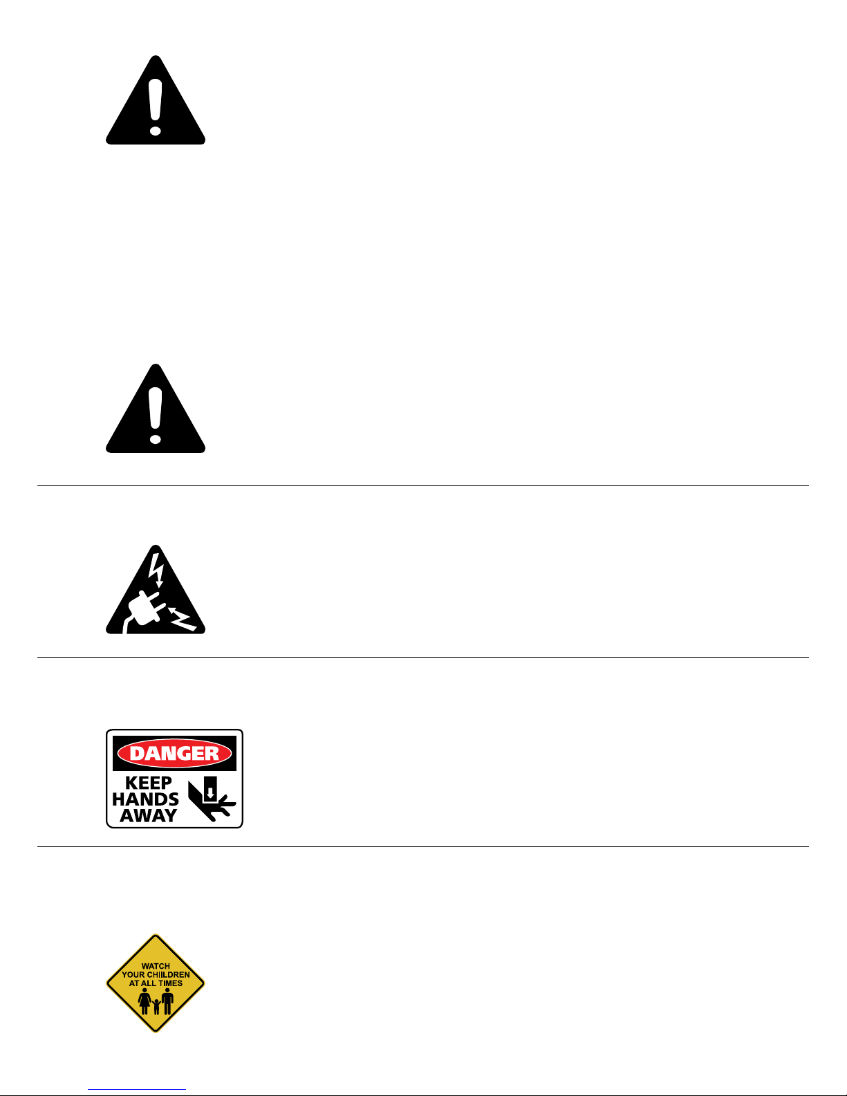
KEEP HANDS AND FINGERS CLEAR.
KEEP ALL OBSTACLES CLEAR OF THE PRODUCT’S PATH.
4. Users. This Product is not intended for use with children, individuals with restricted physical, sensory or mental capabilities, or individuals
who lack experience or knowledge, unless they are supervised by a person who is responsible for their safety or they have received
instructions from a person who is responsible for their safety concerning how the Product must be used. Children should be closely
supervised to ensure that they do not play with the Product and its height adjustment mechanism to avoid risk of physical injury or
electric shock.
KEEP CHILDREN AWAY FROM THE PRODUCT, ITS CONTROL UNITS, AND KEYPADS.
WARNING
DANGER

E. 5/8” Wood Screw x42
F. 1/4”x 5/8” Bolt x2
G. Lock Washer x2
H. 3/4” Wood Screw x4
I. Cord Clip x1
J. M6 x 10mm Bolt x4
K. Star Washer x4
L. 3/16” Allen Wrench x1
M. 4mm Allen Wrench x1
N. 6mm Hex Rod Wrench x1
Left Leg Right Leg
Note
location
of drive
input hole.
Left leg has nuts
for motor mount.
Legs must be in
their lowest position
before installation.
Tools Required for Assembly
A. Power Driver with Adjustable Torque
B. Tape Measure
C. #2 Phillips Head Driver Bit
D. #2 Square Head Drive Bit (Recommended)
A B C D
Hardware and Tools Included for Assembly (may have extra)
E F G H
I J K
L M N
VertDesk Parts
O. Cross Support x1
P. U-Channel x1
Q. Long Hex Rod x1
R. Switch x1
S. Control Box x1
T. Power Cord x1
U. Motor x1
V. Left Leg x1
W. Right Leg x1
X. J-Channel x1
O P Q R
S
T U
V
X
W

Step 1
• Lay the worksurface on a protected
surface with pilot holes facing up.
• Insert hex rod through motor assembly and into
left leg drive input hole.
• If hex rod in the motor is not aligned properly
with drive input, turn hex rod clockwise 1/6th
or 1/3rd of a turn using the motor.
• Hex rod should slide into leg.
Legs must be in
lowest position
before installing
hex rod.
Motor
Assembly
Hex
rod
V
U
Q
Step 2
• Align hex rod with right leg drive input.
• Turn hex rod counter clockwise 1/6th or
1/3rd of a turn with adjustable wrench, if
it is not aligned properly with drive input.
• Slide hex rod into leg and align pre-drilled
holes in worksurface.
W
U
Q
V
N
Important: Please be aware that 5/8” screws
are provided. If your worksurface is 5/8” or thinner,
you will need to supply your own hardware.
N

F
G
Step 3
• Tighten motor mounting bolts after
hex rod is installed.
F G
L
Step 4
• Install u-channel.
• Hole placement may vary,
depending on width of table.
AEE
D
P
Tip: For proper alignment of
pre-drilled holes, start screws
but do not fully tighten until
all are installed.
F
G

Step 5
• Slide cross support over leg
cross support brackets.
Step 6
• Install bolts and do not fully tighten.
O
J K
JK
J
JK
M

Step 7
• Install wood screws and tighten.
Step 9
E
AE
Note:
if you have
a programmable
switch (shown), please refer
to the installation instructions
included with the switch.
Optional:
Programmable
Switch
Step 8
• Fully tighten bolts
in cross support.
Tighten bolts
Switch

Step 10
• Install wire management
J-channel and control box.
Note: The control box, switch
and clips can be installed in any
location, wire lengths permitting.
A
HE
H
S
EE
Control Box Orientation
must be mounted this way
Control box can be relocated but
the orientation of the box must
remain the same. Long side of
control box must align with long
side of the worksurface.
I
II
X
X
R
H

Step 11
Cable Routing Diagram
Use J-channel to Hold Extra Lengths of Cable
Switch Cable
Motor Cable
Switch
Motor Power Cable
Control Box
Power Cable Control Box
End View
Motor Cable
Switch Cable
For the safety of the user and the workstation; the control box contains an internal sensor that is
sensitive to movement, vibration, and collision. For faultless operation, ensure all cables, electronics,
and accessories are cable managed and secured. Excessive load or weight must be distributed evenly.
Failure to follow these guidelines may cause intermittent functionality.
Caution:

If the leg assemblies are at uneven heights, it is usually caused by an improperly installed hex rod. Disassemble one
of the leg assemblies from the worksurface and make sure both ends of the hex rod are properly engaged in the hex
drives near the top of the leg assemblies.
Note
Save for Reference
Standard Switch
Start Up Procedure:
• Plug the power cord into a standard 110V receptacle. A power surge protector
is recommended.
• Press the down arrow until the worksurface reaches its lowest position.
• The workstation is ready for use.
• If the table is not functioning normally or has lost power, perform the reset procedure.
Reset Procedure:
• Unplug the unit from the wall for 10 seconds.
• Clear all obstructions from the travel path of the desk.
• Plug the unit back in the wall.
• Press and hold the down arrow key until the table reaches its lowest position.
Add Container Stops:
• Move the table to the upper or lower desired height.
• Rapidly press 4 times. You will hear a musical tone.
• Rapidly press 2 times. A musical tone plays two times.
- To add the upper container stop press A musical tone plays two times.
- To add the lower container stop press A musical tone plays two times.
Remove Container Stops:
• Move the table to the upper or lower preset height.
• Rapidly press 4 times. You will hear a musical tone.
• Rapidly press 2 times. A musical tone plays two times.
- To delete the upper container stop press You will hear a musical tone.
- To delete the lower container stop press You will hear a musical tone.
Troubleshooting:
If you are having any problems with the operation, contact Beyond the Ofce Door at 866.733.0698

Start Up Procedure:
• Plug the power cord into a standard 110V receptacle. A power surge protector
is recommended.
• Press the down arrow until the worksurface reaches its lowest position.
• The workstation is ready for use.
• If the table is not functioning normally, or has lost power,
perform the reset procedure.
Reset Procedure:
• Unplug the unit from the wall for 10 seconds.
• Clear all obstructions from the travel path of the desk.
• Plug the unit back in the wall.
• Press and hold the down arrow key until the table reaches its lowest position.
See Packaged Instructions for Programmable Options
Optional Programmable Switch (full instructions packaged with switch)

Instructions to Install a Track on a Vert Desk Workstation
Tools Required for Assembly
A. Power Driver with Adjustable Torque
A
Hardware Included for Assembly
B. 3/4” Wood Screw x2
B
Step 1: Place the front of the track against the bottom of the worksurface 1/8”- 5/8” from the front edge of the
worksurface and place the back of the track on top of the U-channel’s lip.
Step 2: Attach the track to the worksurface using four wood screws. Do not over-tighten the wood screws.
Use a low torque setting on the power driver.
Step 3: Complete the installation using the instructions that came with the product you are installing.
Other manuals for VERTDESK V3
1
Table of contents