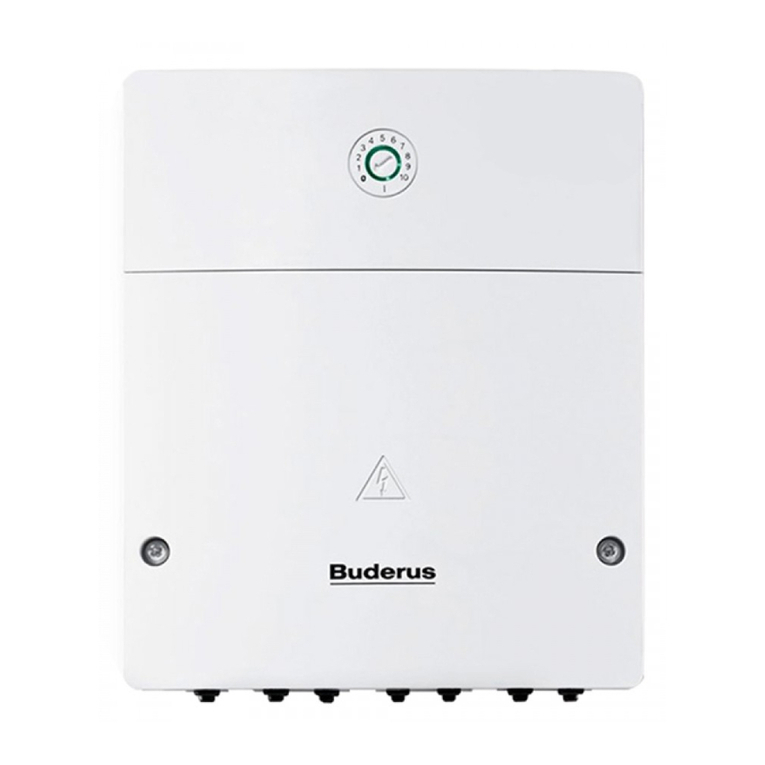
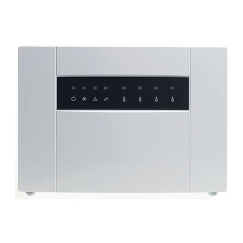
Buderus MP100 EMS plus User manual

[de] Installationsanleitung für das Fachhandwerk 2
[en] Installation instructions for skilled labour 7
[fr] Notice d'installation pour le professionnel 12
[cs] Návod kinstalaci pro odbornou firmu 17
[da] Installationsvejledning til installatøren 22
[el] Οδηγίες εγκατάστασης για τον τεχνικό 27
[fi] Asennusohje alan ammattiasentajalle 32
[fl] Installatiehandleiding voor de vakman 37
[it] Istruzioni d’installazione per i tecnici specializzati 42
[no] Installasjonsveiledning for autorisert personell 47
[pl] Instrukcja montażu dla instalatora 52
[sk] Návod na inštaláciu pre odborných pracovníkov 57
[sl] Navodila za montažo 62
[sv] Installationsanvisning 67
[tr] Yetkili Servis İçin Montaj Kılavuzu 72
MP100
1
2
3
4567
8
9
10
0
1
2
3
4567
8
9
10
0
EMS plus
6 720 645 409-00.2O
6 720 808 905 (2014/04)

6 720 808 905 (2014/04) MP100
2 |
Inhaltsverzeichnis
Inhaltsverzeichnis
1 Symbolerklärung und Sicherheitshinweise . . . . . . . . 2
1.1 Symbolerklärung . . . . . . . . . . . . . .. . . . . . . . . . . . . 2
1.2 Allgemeine Sicherheitshinweise . . . . . . . . . . . . . . 2
2 Angaben zum Produkt . . . . . . . . . . . . . . . . . . . . . . . . . . 3
2.1 Lieferumfang . . . . . . . . . . . . . .. . . . . . . . . . . . . . . . 3
2.2 Technische Daten . . . . . . . . . . . . . . . .. . . . . . . . . . 3
2.3 Reinigung und Pflege . . . . . . . . . . . . .. . . . . . . . . . 4
2.4 Ergänzendes Zubehör . . . . . . . . . . . . . . . . . . . . . . . 4
3 Installation . . . . . . . . . .. . . . . . . . . . . . . . . .. . . . . . . . . . 4
3.1 Installation . . . . . . . . . . . . . . . . . . . . . . . . . . . . . . . 4
3.2 Elektrischer Anschluss . . . . . . . . . . . . . .. . . . . . . 4
3.2.1 Anschluss BUS-Verbindung und
Temperaturfühler (Kleinspannungsseite) . . . . . . .4
3.2.2 Anschluss Spannungsversorgung, Pumpe und
Mischer (Netzspannungsseite) . . . . . . . . . . . . . ..4
3.2.3 Anschlusspläne mit Anlagenbeispielen . . . . . . . . 5
4 Inbetriebnahme . . . . . . . . . . . . . . . . . . . . . . . . . . . .. . . . 5
5 Störungen beheben . . . . . . . . . . . . . . . . . . . . .. . . . . . . 5
6 Umweltschutz/Entsorgung . . . . . . . . . . . . . . . . . . . . . . 6
1 Symbolerklärung und Sicherheits-
hinweise
1.1 Symbolerklärung
Warnhinweise
Folgende Signalwörter sind definiert und können im vorliegen-
den Dokument verwendet sein:
•HINWEIS bedeutet, dass Sachschäden auftreten können.
•VORSICHT bedeutet, dass leichte bis mittelschwere Per-
sonenschäden auftreten können.
•WARNUNG bedeutet, dass schwere bis lebensgefährliche
Personenschäden auftreten können.
•GEFAHR bedeutet, dass schwere bis lebensgefährliche
Personenschäden auftreten werden.
Wichtige Informationen
Weitere Symbole
1.2 Allgemeine Sicherheitshinweise
Diese Installationsanleitung richtet sich an Fachleute für Was-
serinstallationen, Heizungs- und Elektrotechnik.
▶ Installationsanleitungen (Wärmeerzeuger, Module, usw.)
vor der Installation lesen.
▶ Sicherheits- und Warnhinweise beachten.
▶ Nationale und regionale Vorschriften, technische Regeln
und Richtlinien beachten.
▶ Ausgeführte Arbeiten dokumentieren.
Bestimmungsgemäße Verwendung
▶ Produkt ausschließlich zur Regelung von Heizungsanlagen
in Ein- oder Mehrfamilienhäusern verwenden.
Jede andere Verwendung ist nicht bestimmungsgemäß. Daraus
resultierende Schäden sind von der Haftung ausgeschlossen.
Installation, Inbetriebnahme und Wartung
Installation, Inbetriebnahme und Wartung darf nur ein zugelas-
sener Fachbetrieb ausführen.
▶ Nur Originalersatzteile einbauen.
Elektroarbeiten
Elektroarbeiten dürfen nur Fachleute für Elektroinstallationen
ausführen.
▶ Vor Elektroarbeiten:
– Netzspannung (allpolig) spannungsfrei schalten und
gegen Wiedereinschalten sichern.
– Spannungsfreiheit feststellen.
Warnhinweise im Text werden mit einem
Warndreieck gekennzeichnet.
Zusätzlich kennzeichnen Signalwörter die Art und
Schwere der Folgen, falls die Maßnahmen zur Ab-
wendung der Gefahr nicht befolgt werden.
Wichtige Informationen ohne Gefahren für
Menschen oder Sachen werden mit dem ne-
benstehenden Symbol gekennzeichnet.
Symbol Bedeutung
▶Handlungsschritt
Querverweis auf eine andere Stelle im Dokument
• Aufzählung/Listeneintrag
– Aufzählung/Listeneintrag (2. Ebene)
Tab. 1

6 720 808 905 (2014/04)MP100
Angaben zum Produkt
| 3
▶ Produkt benötigt unterschiedliche Spannungen.
Kleinspannungsseite nicht an Netzspannung anschließen
und umgekehrt.
▶ Anschlusspläne weiterer Anlagenteile ebenfalls beachten.
Übergabe an den Betreiber
Weisen Sie den Betreiber bei der Übergabe in die Bedienung
und die Betriebsbedingungen der Heizungsanlage ein.
▶ Bedienung erklären – dabei besonders auf alle sicherheits-
relevanten Handlungen eingehen.
▶ Darauf hinweisen, dass Umbau oder Instandsetzungen nur
von einem zugelassenen Fachbetrieb ausgeführt werden
dürfen.
▶ Auf die Notwendigkeit von Inspektion und Wartung für den
sicheren und umweltverträglichen Betrieb hinweisen.
▶ Installations- und Bedienungsanleitungen zur Aufbewah-
rung an den Betreiber übergeben.
Schäden durch Frost
Wenn die Anlage nicht in Betrieb ist, kann sie einfrieren:
▶ Hinweise zum Frostschutz beachten.
▶ Anlage immer eingeschaltet lassen, wegen zusätzlicher
Funktionen, z. B. Warmwasserbereitung oder Blockier-
schutz.
▶ Auftretende Störung umgehend beseitigen.
2 Angaben zum Produkt
• Das Modul dient zur Ansteuerung eines Schwimmbades in
Verbindung mit einer Wärmepumpe mit einer EMS plus-
Schnittstelle.
• Das Modul dient zur Erfassung der Schwimmbadtempera-
tur und zur Ansteuerung eines Mischers auf Vorgabe der
Wärmepumpe.
• Blockierschutz: Der angeschlossene Mischermotor wird
überwacht und nach 24Stunden Stillstandautomatisch für
kurze Zeit in Betrieb genommen. Dadurch wird ein Festsit-
zen des Mischers verhindert.
Unabhängig von der Anzahl anderer BUS-Teilnehmer, ist maxi-
mal ein MP100 in einer Anlage erlaubt.
2.1 Lieferumfang
Bild 1, Seite 77:
[1] Modul
[2] Beutel mit Installationszubehör
[3] Installations-Set Schwimmbad-Temperaturfühler TC1
[4] Installationsanleitung
2.2 Technische Daten
Dieses Produkt entspricht in Konstruktion und
Betriebsverhalten den europäischen Richtlinien
sowie den ergänzenden nationalen Anforderun-
gen. Die Konformität wurde mit der CE-Kennzeichnung nachge-
wiesen.
Technische Daten
Abmessungen
(B×H×T)
151 × 184 × 61 mm (weitere
Maße Bild 2, Seite 77)
Maximaler
Leiterquerschnitt
•Anschlussklemme
230 V
•Anschlussklemme
Kleinspannung
•2,5mm
2
•1,5mm
2
Nennspannungen
•BUS
• Spannungsversor-
gung des Moduls
• Bedieneinheit
•Mischer
• 15 V DC (verpolungssicher)
• 230 V AC, 50 Hz
• 15 V DC (verpolungssicher)
• 230 V AC, 50 Hz
Sicherung 230 V, 5 AT
BUS-Schnittstelle EMS plus
Leistungsaufnahme –
Standby
< 1 W
maximale
Leistungsabgabe
• pro Anschluss (VC1) • 100 W
Messbereich
Temperaturfühler
• untere Fehlergrenze
•Anzeigebereich
•obereFehlergrenze
•<–10°C
• 0 ... 100 °C
•>125°C
zulässige Umgebungs-
temperatur
0 ... 60 °C
Schutzart
•beiEinbauinWär-
meerzeuger
• bei Wandinstallation
•wirdvonSchutzartdes
Wärmeerzeugers bestimmt
•IP44
Schutzklasse I
Ident.-Nr. Typschild (Bild 15, Seite 82)
Tab. 2

6 720 808 905 (2014/04) MP100
4 |
Installation
2.3 Reinigung und Pflege
▶ BeiBedarfmiteinemfeuchtenTuchdasGehäuseabreiben.
Dabei keine scharfen oder ätzenden Reinigungsmittel ver-
wenden.
2.4 Ergänzendes Zubehör
Genaue Angaben zu geeignetem Zubehör entnehmen Sie bitte
dem Katalog.
• Für gemischten Schwimmbadkreis:
– Mischermotor; Anschluss an VC1
– Schwimmbad-Temperaturfühler; Anschluss an TC1.
Installation des ergänzenden Zubehörs
▶ Ergänzendes Zubehör entsprechend den gesetzlichen Vor-
schriften und der mitgelieferten Anleitungen installieren.
3 Installation
3.1 Installation
▶ Modul an einer Wand (Bild 3 bis Bild 5, Seite 78) oder
an einer Hutschiene (Bild 6, Seite 79) installieren.
▶ Beim Entfernen des Moduls von der Hutschiene Bild 7 auf
Seite 79 beachten.
▶ Schwimmbad-Temperaturfühler TC1 (Bild 1 [3],
Seite 77) an geeigneter Stelle installieren (Bild 16,
Seite 83).
3.2 Elektrischer Anschluss
▶ Unter Berücksichtigung der geltenden Vorschriften für den
Anschluss mindestens Elektrokabelder Bauart H05 VV-...
verwenden.
3.2.1 Anschluss BUS-Verbindung und Temperaturfühler
(Kleinspannungsseite)
▶ Bei unterschiedlichen Leiterquerschnitten Verteilerdose
für den Anschluss der BUS-Teilnehmer verwenden.
▶ BUS-Teilnehmer [B] über Verteilerdose [A] in Stern
(Bild 12, Seite 81) oder über BUS-Teilnehmer mit 2
BUS-Anschlüssen in Reihe (Bild 16, Seite 83) schalten.
Maximale Gesamtlänge der BUS-Verbindungen:
• 100 m mit 0,50 mm2Leiterquerschnitt
• 300 m mit 1,50 mm2Leiterquerschnitt
▶ Um induktive Beeinflussungen zu vermeiden: Alle
Kleinspannungskabelvon NetzspannungführendenKabeln
getrennt verlegen (Mindestabstand 100 mm).
▶ Bei induktiven äußeren Einflüssen (z. B. von PV-Anlagen)
Kabel geschirmt ausführen (z. B. LiYCY) und Schirmung
einseitig erden. Schirmung nicht an Anschlussklemme für
Schutzleiter im Modul anschließen, sondern an Hauser-
dung, z. B. freie Schutzleiterklemme oder Wasserrohre.
Bei Verlängerung der Fühlerleitung folgende Leiterquerschnit-
te verwenden:
• Bis 20 m mit 0,75 mm2bis 1,50 mm2Leiterquerschnitt
• 20 m bis 100 m mit 1,50 mm2Leiterquerschnitt
▶ Kabel durch die bereits vormontierten Tüllen führen und
gemäß den Anschlussplänen anklemmen.
3.2.2 Anschluss Spannungsversorgung, Pumpe und
Mischer (Netzspannungsseite)
▶ Nur Elektrokabel gleicher Qualität verwenden.
▶ Auf phasenrichtige Installation des Netzanschlusses ach-
ten.
Netzanschluss über einen Schutzkontaktstecker ist nicht
zulässig.
°C Ω°C Ω°C Ω
20 14772 44 5730 68 2488
26 11500 50 4608 74 2053
32 9043 56 3723 80 1704
38 7174 62 3032 86 1421
Tab. 3 Widerstandswerte des beiliegenden Schwimmbad-
Temperaturfühlers
GEFAHR: Stromschlag!
▶ Vor Installation dieses Produktes: Wär-
meerzeuger und alle weiteren BUS-Teil-
nehmer allpolig von der Netzspannung
trennen.
▶ Vor Inbetriebnahme: Abdeckung anbrin-
gen (Bild 14, Seite 81).
Wenn die maximale Gesamtlänge der BUS-Ver-
bindungen zwischen allen BUS-Teilnehmern
überschritten wird oder im BUS-System eine
Ringstruktur vorliegt, ist die Inbetriebnahme
der Anlage nicht möglich.
Die Belegung der elektrischen Anschlüsse ist
von der installierten Anlage abhängig. Die in
Bild 8 bis 11, ab Seite 79 dargestellte Be-
schreibung ist ein Vorschlag für den Ablauf des
elektrischen Anschlusses. Die Handlungs-
schritte sind teilweise nicht schwarz darge-
stellt. Damit ist leichter zu erkennen, welche
Handlungsschritte zusammengehören.

6 720 808 905 (2014/04)MP100
Inbetriebnahme
| 5
▶ An den Ausgängen nur Bauteile und Baugruppen gemäß
dieser Anleitung anschließen. Keine zusätzlichen
Steuerungen anschließen, die weitere Anlagenteile steu-
ern.
▶ Kabeldurchdie Tüllenführen,gemäß den Anschlussplänen
anklemmen und mit den im Lieferumfang enthaltenen Zug-
entlastungen sichern (Bild 8 bis 11, ab Seite 79).
3.2.3 Anschlusspläne mit Anlagenbeispielen
Die hydraulischen Darstellungen sind nur schematisch und ge-
ben einen unverbindlichen Hinweis auf eine mögliche hydrauli-
sche Schaltung.
▶ Sicherheitseinrichtungen nach den gültigen Normen und
örtlichen Vorschriften ausführen.
▶ Weitere Informationen und Möglichkeiten den Planungsun-
terlagen oder der Ausschreibung entnehmen.
Legende zu Bild 16:
Schutzleiter
ϑTemperatur/Temperaturfühler
LPhase(Netzspannung)
N Neutralleiter
Anschlussklemmenbezeichnungen:
230 V AC Anschluss Netzspannung
BUS Anschluss BUS-System EMS plus
MC1 Externes Reinigungssystem der Schwimmbadsteu-
erung (Monitor Circuit, optional)
MD1 Externe Sperre durch Kunden (Monitor Dew point,
optional)
OC1 Ohne Funktion
PC1 Ohne Funktion
T0 Ohne Funktion
TC1 Anschluss Schwimmbad-Temperaturfühler (Tem-
perature sensor Circuit)
VC1 Anschluss Mischermotor (Valve Circuit):
Anschlussklemme 43: Mischer auf (mehr Wärmezu-
fuhr zum Schwimmbad)
Anschlussklemme 44: Mischer zu (weniger Wärme-
zufuhr zum Schwimmbad)
Bestandteile der Anlage:
230 V AC Netzspannung
BUS BUS-System EMS plus
CON Bedieneinheit EMS plus
HS Wärmeerzeuger (Heat Source)
MC1 Temperaturwächter im zugeordneten Heizkreis (bei
ungemischtem Heizkreis optional; wenn kein Tem-
peraturwächter,Brücke(Bild 1 [2],Seite 77) an
Anschlussklemme MC1 anschließen)
MP100 Modul MP100
TC1 Schwimmbad-Temperaturfühler
VC1 Mischermotor
4 Inbetriebnahme
1. Der gesamten Anlage die Netzspannung zuschalten.
Wenn die Betriebsanzeige des Moduls dauernd grün leuchtet:
2. Bedieneinheit gemäß beiliegenderInstallationsanleitung in
Betrieb nehmen und entsprechend einstellen.
5Störungenbeheben
Die Betriebsanzeige zeigt den Betriebszustand des Moduls.
Die maximale Leistungsaufnahme der ange-
schlossenenBauteile und Baugruppen darfdie
in den technischen Daten des Moduls angege-
bene Leistungsabgabe nicht überschreiten.
▶ Wenn die Netzspannungsversorgung nicht
über die Elektronik des Wärmeerzeugers
erfolgt, bauseits zur Unterbrechung der
Netzspannungsversorgung eine allpolige
normgerechte Trennvorrichtung (nach
EN 60335-1) installieren. Alle elektrischen Anschlüsse richtig anschlie-
ßen und erst danach die Inbetriebnahme
durchführen!
▶ Installationsanleitungen aller Bauteile und
Baugruppen der Anlage beachten.
▶ Spannungsversorgung nur einschalten,
wenn alle Module eingestellt sind.
Nur Originalersatzteile verwenden. Schäden,
die durch nicht vom Hersteller gelieferte Er-
satzteile entstehen, sind von der Haftung aus-
geschlossen.
Wenn sich eine Störung nicht beheben lässt,
bitte an den zuständigen Servicetechniker
wenden.
0
1
2
3
4567
8
9
10
6 720 645 409-20.1o

6 720 808 905 (2014/04) MP100
6 |
Umweltschutz/Entsorgung
Einige Störungen werden auch im Display der dem Heizkreis
zugeordneten und ggf. der übergeordneten Bedieneinheit an-
gezeigt.
6 Umweltschutz/Entsorgung
Umweltschutz ist ein Unternehmensgrundsatz der Bosch
Gruppe.
Qualität der Produkte, Wirtschaftlichkeit und Umweltschutz
sind für uns gleichrangige Ziele. Gesetze und Vorschriften zum
Umweltschutz werden strikt eingehalten.
Zum Schutz der Umwelt setzen wir unter Berücksichtigung
wirtschaftlicher Gesichtspunkte bestmögliche Technik und
Materialien ein.
Verpackung
Bei der Verpackung sind wir an den länderspezifischen Verwer-
tungssystemen beteiligt, die ein optimales Recycling gewähr-
leisten.
AlleverwendetenVerpackungsmaterialien sind umweltverträg-
lich und wiederverwertbar.
Elektro- und Elektronik-Altgeräte
Nicht mehr gebrauchsfähige Elektro- oder
Elektronikgeräte müssen getrennt gesammelt
und einer umweltgerechten Verwertung zuge-
führt werden (Europäische Richtlinie über
Elektro- und Elektronik-Altgeräte).
Nutzen Sie zur Entsorgung von Elektro- oder
Elektronik-Altgeräten die länderspezifischen
Rückgabe- und Sammelsysteme.
Betriebs-
anzeige
Mögliche
Ursache Abhilfe
dauernd
aus
Spannungsver-
sorgung unter-
brochen.
▶ Spannungsversorgung ein-
schalten.
Sicherung
defekt
▶ Bei ausgeschalteter Span-
nungsversorgung Siche-
rung austauschen
(Bild 13, Seite 81).
Kurzschluss
in der BUS-Ver-
bindung
▶ BUS-Verbindungprüfenund
ggf. instandsetzen.
dauernd
rot
interne Störung ▶ Modul austauschen.
grün
blinkend
maximale Ka-
bellänge BUS-
Verbindung
überschritten
▶KürzereBUS-Verbindung
herstellen.
Störungs-
anzeige im
Display der
Bedieneinheit
▶ Zugehörige Anleitung der
Bedieneinheit und das Ser-
vicehandbuch enthalten
weitere Hinweise zur Stö-
rungsbehebung.
dauernd
grün
keine Störung Normalbetrieb
Tab. 4

6 720 808 905 (2014/04)MP100
Contents
| 7
Contents
1 Key to symbols and safety instructions . . . . . . . . . . . . 7
1.1 Key to symbols . . . . . . . . . . . . . . . . . .. . . . . . . . . . . 7
1.2 General safety instructions . . . . . . . . . . . . . . . . . . . 7
2 Product details . . . . . . . . . . . . . . . . . . . . . . . . . . . . .. . . . 8
2.1 Standard delivery . . . . . . . . . . . . .. . . . . . . . . . . . . . 8
2.2 Technical data . . . . . . . . . . . . . . . . . . . . . . . . . .. . . . 8
2.3 Cleaning and care . . . . . . . . . . . . . . . .. . . . . . . . . . . 9
2.4 Supplementary accessories . . . . . . . . . . . . . . . . . . . 9
3 Installation . . . . . . . . . . . . . . . . . . . .. . . . . . . . . . . . . . . .. 9
3.1 Installation . . . . . . . . . . . . . . . . . . . . . . . . . . . .. . . . 9
3.2 Electrical connection . . . . . . . . . . . . . . . . . . . . . . . 9
3.2.1 Connecting the BUS connection and
temperature sensor (extra-low voltage side) . . . . 9
3.2.2 Connecting the power supply, pump and
mixing valve (mains voltage side) . . . . . . . . . . . .. 9
3.2.3 Wiring diagrams with system examples . . . . . . . 10
4 Commissioning . . . . . . . . . . . . . . . . . . .. . . . . . . . . . . . 10
5 Troubleshooting . . . . . . . . . . . . . . .. . . . . . . . . . . . . . . 10
6 Environment/disposal . . . . . . . . . . . . . . . . . . . . . . . . . 11
1 Key to symbols and safety instructions
1.1 Key to symbols
Warnings
The following keywords are defined and can be used in this
document:
•NOTICEindicates a situation that could resultin damage to
property or equipment.
•CAUTION indicates a situation that could result in minor to
medium injury.
•WARNING indicates a situation that could result in severe
injury or death.
•DANGER indicates a situation that will result in severe
injury or death.
Important information
Additional symbols
1.2 General safety instructions
These installation instructions are intended for a competent
person.
▶ Read the installation instructions (heat appliances,
modules, etc.) before installation.
▶ Observe safety instructions and warnings.
▶ Observe national and regional regulations, technical rules
and guidelines.
▶ Keep a record of any work carried out.
Determined use
▶ The product must only be used for controlling heating
systems.
Any other use is considered improper. Any damage that may
result is excluded from liability.
Installation, commissioning and maintenance
Installation, commissioning and maintenance must only be
carried out by a competent person.
▶ Only install genuine spare parts.
Electrical work
Electrical work must only be carried outby qualified
electricians.
▶ Before carrying out electrical work:
– Isolateall polesof the mains voltage and secure against
reconnection.
– Using suitable means, test the power supply is
disconnected.
Warnings in this document are identified by
a warning triangle printed against a grey
background.
Keywords at the start of a warning indicate
the type and seriousness of the ensuing risk
if measures to prevent the risk are not taken.
This symbol indicates important information
where there is no risk to people or property.
Symbol Explanation
▶ Step in an action sequence
Cross-reference to another part of the document
•Listentry
– List entry (second level)
Table 1

6 720 808 905 (2014/04) MP100
8 |
Product details
▶Theproductrequiresdifferent voltages.
Do not connect the extra-low voltage side to the mains
voltage or vice versa.
▶ Also observe connection diagrams of other system
components.
Handover to the end user
When handing over the heating system, explain the operating
conditions to the user.
▶ Explain how to operate the heating system, with particular
emphasis on all safety-related actions.
▶ Explain that conversions or maintenance must only be
carried out by a competent person.
▶ Point out the need for inspections and maintenance for
safe and environmentally friendly operation.
▶ Theinstallation and operatinginstructions must be givento
the end user for keeping.
Damage caused by frost
The system can freeze if it is switched off:
▶ Observe the notices regarding frost protection.
▶ Due to the additional functions, e.g. DHW heating or anti-
seizing protection, the system should always be left on.
▶ Correct any faults immediately.
2 Product details
• The module serves to activate a swimming pool connected
to a heat pump with a EMS plus interface.
• The module serves to determine the swimming pool
temperature and activate a mixer as required by the heat
pump.
• Anti-seizing function: the connected mixing valve actuator
is monitored and run automatically for a short period after
24 hours of downtime. This prevents the mixer from
seizing up.
A maximum of one MP100 is permitted in a system,
irrespective of the number of other BUS nodes.
2.1 Standard delivery
Fig. 1, page 77:
[1] Module
[2] Bag with installation accessories
[3] Swimming pool temperature sensor TC1 installation set
[4] Installation instructions
2.2 Technical data
Design and operation of this product conform to
European Directives and the supplementary
national requirements. Its conformityis
demonstrated by the CE marking .
Technical data
Measurements
(W × H × D)
151 × 184 × 61 mm (further
dimensions Fig. 2, page 77)
Maximum conductor
cross-section
• 230 V terminal
•Extra-lowvoltage
terminal
•2.5mm
2
•1.5mm
2
Rated voltages
•BUS
• Module power supply
•Userinterface
•Mixer
• 15 V DC (reverse-polarity-
protected)
• 230 V AC, 50 Hz
• 15 V DC (reverse-polarity-
protected)
• 230 V AC, 50 Hz
Circuit breaker 230 V, 5 AT
BUS interface EMS plus
Power consumption on
– standby
<1W
Maximum output
• Per connection
(VC1) • 100 W
Temperature sensor
capturing range
• lower fault limit
•displayrange
• upper fault limit
•<–10°C
• 0 ... 100 °C
•>125°C
Permissible ambient
temperature
0 ... 60 °C
IP rating
• For installation in
heat source
• For wall-mounted
installation
• Determined by the IP rating of
the heat appliance
•IP44
Protection class I
ID no. Data plate (Fig. 15, page 82)
Table 2

6 720 808 905 (2014/04)MP100
Installation
| 9
2.3 Cleaning and care
▶ If required, wipe the enclosure with a damp cloth. Never
use chemically aggressive or acidic cleaning agents.
2.4 Supplementary accessories
Forpreciseinformationregardingsuitableaccessories,referto
the catalogue.
• For mixed swimming pool circuit:
– Mixer motor; connection to VC1
–
Swimming pool temperature sensor; connection to TC1.
Installation of supplementary accessories
▶ Fit accessories according to legal requirements and the
installation instructions provided.
3 Installation
3.1 Installation
▶ Install the module on a wall (Fig. 3 to Fig. 5, page 78) or
on a mounting rail (Fig. 6, page 79).
▶ When removing the module from the mounting rail, refer to
Fig. 7 on page 79.
▶ Install the swimming pool temperature sensor TC1
(Fig. 1 [3], page 77) in a suitable place (Fig. 16,
page 83).
3.2 Electrical connection
▶ Observe current regulations applicable to power
connections, and use at least cable type H05 VV-…
3.2.1 Connecting the BUS connection and temperature
sensor (extra-low voltage side)
▶ If the conductor cross-sections are different, use the
junction box to connect the BUS nodes.
▶ Connect BUS nodes [B] via junction box [A] in star
(Fig. 12, page 81) or via BUS nodes with 2 BUS
connections in series (Fig. 16, page 83).
Maximum total length of BUS connections:
• 100 m at 0.50 mm2conductor cross-section
• 300 m at 1.50 mm2conductor cross-section
▶ Alllow voltage leadsmust be routed separatelyfromcables
carrying mains voltage to avoid inductive interference
(minimum separation 100 mm).
▶ In the case of external inductive interferences (e.g. from
PV systems), use shielded cables (e.g. LIYCY) and earth
the shield on one side. The shield should be connected to
the building's earthing system, e.g. to a free earth
conductor terminal or water pipe, and not to the earth
connecting terminal in the module.
When sensor leads are extended, apply the following lead
cross-sections:
• Up to 20 m with 0.75 mm2to 1.50 mm2conductor cross-
section
• 20 m up to 100 m with 1.50 mm2conductor cross-section
▶ Route cables through the grommets provided and connect
them as shown in the connection diagrams.
3.2.2 Connecting the power supply, pump and mixing
valve (mains voltage side)
▶ Only use cable of comparable quality.
▶ Ensure correct polarity on the power supply.
Do not use standard plugs on fly leads for power supply.
°C Ω°C Ω°C Ω
20 14772 44 5730 68 2488
26 11500 50 4608 74 2053
32 9043 56 3723 80 1704
38 7174 62 3032 86 1421
Table 3 Pressure drop values of the connected swimming
pool temperature sensor
DANGER: Risk of electric shock!
▶Beforeinstallingthisproduct: completely
disconnect heat appliances and all other
BUS nodes from the mains voltage.
▶ Before commissioning: fit the cover
(Fig. 14, page 81).
If the maximum total length of the BUS
connections between all BUS nodes is
exceeded, or if the BUS system is realised as a
ring structure, the system cannot be
commissioned.
The assignment of the electrical connections
depends on the system installed. The
description shown in Fig. 8 to Fig. 11, from
page 79onwards, suggestsa possibleprocess
for assigning the electrical connections. Some
ofthe steps arenotshown in black.This makes
it easier to see which steps belong together.
6 720 808 905 (2014/04) MP100
10 |
Commissioning
▶ Only connect components not exceeding the outputs
stated in these instructions. Do not connect additional
control units that regulate other system components.
▶ Route cables through the grommets provided, connect
them as shown in the connection diagrams and secure
them with the strain relief supplied inthe standard delivery
(Fig. 8 to 11, from page 79 onwards).
3.2.3 Wiring diagrams with system examples
The circuit diagrams are only schematic illustrations and
provide a non-binding indication of possible hydraulic circuits.
▶ Install safety equipment in accordance with applicable
standards and local regulations.
▶ For further information and options referto the technical
guides or the tendering documents.
Key to Fig. 16:
Earth lead
ϑTemperature/temperature sensor
L Phase (mains voltage)
N Neutral conductor
Terminal designations:
230 V AC Mains voltage connection
BUS EMS plus BUS system connection
MC1 External cleaning system of swimming pool control
system (Monitor Circuit, optional)
MD1 External customer block (Monitor Dew point,
optional)
OC1 No function
PC1 No function
T0 No function
TC1 Swimming pool temperature sensor connection
(Temperature sensor Circuit)
VC1 Mixer motor connection (Valve Circuit):
Terminal 43: mixer open (more heat supply to
swimming pool)
Terminal 44: mixer closed (less heat supply to
swimming pool)
System components:
230 V AC Mains voltage
BUS EMS plus BUS system
CON EMS plus user interface
HS Heating appliance (heat source)
MC1 Temperature limiter in assigned heating circuit
(optional for heating circuit without mixing valve;
if there is no temperature switch, connect jumper
(Fig. 1 [2], page 77) to terminal MC1)
MP100 module MP100
TC1 Swimming pool temperature sensor
VC1 Mixer motor
4 Commissioning
1. Connect the entire system to the mains voltage.
When the module indicator lights up green continuously:
2. Commission and set up the user interface as described in
the accompanying installation instructions.
5 Troubleshooting
The indicator shows the operating condition of the module.
The maximum power consumption of the con-
nected components and assemblies must not
exceed the output stated in the module
specification.
▶ If the mains voltage is not supplied via the
heat appliance electronic system, install a
standard isolator (in accordance with
EN 60335-1) on site to disconnect all
poles from the power supply. First make all electrical connections and then
carry out the commissioning!
▶ Follow all installation instructions for all
components and assemblies in the
system.
▶ Only switch on the power supply when all
modules are set up.
Use only original spare parts. Any damage
resultingfromsparepartsthatarenotsupplied
by the manufacturer is excluded from liability.
Ifafaultcannotbe rectified,pleasecontactthe
responsible service engineer.
0
1
2
3
4567
8
9
10
6 720 645 409-20.1o

6 720 808 905 (2014/04)MP100
Environment/disposal
| 11
Certain faults are also shown on the display of the user
interface assigned to the heating circuit,and on the display of
the higher-level user interface where applicable.
6 Environment/disposal
Environmental protection is a fundamental corporate strategy
of the Bosch Group.
The quality of our products, their economy and environmental
safety are all of equal importance to us and all environmental
protection legislation and regulations are strictly observed.
We use the best possible technologyand materials for
protecting the environment taking account of economic
considerations.
Packaging
We participate in the recycling programmes of the countries in
which our products are sold to ensure optimum recycling.
All of our packaging materials are environmentally compatible
and can be recycled.
Old electrical and electronic appliances
Electrical or electronic devices that are no
longer serviceable must be collected
separately and sent for environmentally
compatible recycling (in accordance with the
European Waste Electrical and Electronic
Equipment Directive).
To dispose of old electrical or electronic
devices, you should use the return and
collection systems put in placein the country
concerned.
Indicator Possible cause Remedy
Constantly
OFF
Power supply
interrupted.
▶ Switch on the power
supply.
Fuse is broken ▶ When the power supply
is switched off, replace
the fuse (Fig. 13,
page 81).
Short circuit in
the BUS
connection
▶ Check BUS connection
and repair if required.
Constantly
red
Internal fault ▶ Replace module.
Flashing
green
Maximumcable
length for BUS
connection
exceeded.
▶ Make shorter BUS
connection.
Fault shown
on user
interface
display
▶Theuserinterface
instructions and the
service manual contain
further information on
troubleshooting.
Constantly
green
No fault Standard operation.
Table 4

6 720 808 905 (2014/04) MP100
12 |
Table des matières
Table des matières
1 Explication des symboles et mesures de sécurité . . 12
1.1 Explication des symboles . . . . . . . . . . . . . . . . . . . 12
1.2 Consignes générales desécurité . . . . . . . . . . . . . 12
2 Informations produit . . . . . . . . . . . . . .. . . . . . . . . . . . 13
2.1 Pièces fournies . . . . . . . . . . . . . . . . . .. . . . . . . . . 13
2.2 Données techniques . . . . . . . . . . . . . . . . . . . . . . . 13
2.3 Nettoyage et entretien . . . . . . . . . . . . . . . . . . . . . 14
2.4 Accessoires complémentaires . . . . . . . . . . . . . . . 14
3 Installation . . . . . . . . . . . . . . . . . . . . . . . . . .. . . . . . . . . 14
3.1 Installation . . . . . . . . . . . . . . . . . . . . . . . . . . .. . . 14
3.2 Raccordement électrique . . . . . . . . . . . . . . . . . . 14
3.2.1 Raccordement liaison BUS et sonde de
température (côté basse tension) . . . . . . . . . . . 14
3.2.2 Raccordement tension réseau, pompe et
mélangeur (côté tension de réseau) . . . . . . . . . 14
3.2.3 Schémas de branchement avec exemples
d'installation . . . . . . . . . . . . . . . . . . . . . . . . . . . . 15
4 Mise en service . . . . . . . . . . . . . . . . . . . . . . . . .. . . . . . 15
5 Elimination des défauts . . . . . . . . . . . . . . .. . . . . . . . . 15
6 Protection de l’environnement/Recyclage . . . . . . . . 16
1 Explication des symboles et mesures
de sécurité
1.1 Explication des symboles
Avertissements
Les mots de signalement suivants sont définis et peuvent être
utilisés dans le présent document :
•AVIS signale le risque de dégâts matériels.
•PRUDENCEsignale lerisque d’accidentscorporels légers à
moyens.
•AVERTISSEMENT signale le risque d’accidents corporels
graves à mortels.
•DANGER signalela survenued’accidents mortels en cas de
non respect.
Informations importantes
Autres symboles
1.2 Consignes générales de sécurité
Cette notice d’installation s’adresse aux spécialistes des installa-
tions gaz et eau, des techniques de chauffage et de l’électronique.
▶ Lire les notices d’installation (générateur de chaleur,
modules, etc.) avant l’installation.
▶ Respecter les consignes de sécurité et d’avertissement.
▶ Respecter les prescriptions nationales et régionales, ainsi
que les règles techniques et directives.
▶ Documenter les travaux effectués.
Utilisation conforme à l’usage prévu
▶ Ce produit doit être utilisé exclusivement pour réguler les
installations de chauffage dans les maisons individuelles et
petits immeubles collectifs.
Toute autre utilisation n’est pas conforme. Les dégâts éven-
tuels qui en résulteraient sont exclus de la garantie.
Installation, mise en service et entretien
L’installation, la première mise en service et l’entretien doivent
être exécutés par un professionnel agréé.
▶ N’utiliser que des pièces de rechange d’origine.
Travaux électriques
Les travaux électriques sont réservés à des spécialistes en
matière d’installations électriques.
▶ Avant les travaux électriques :
– couper le courant sur tous les pôles et sécuriser contre
tout réenclenchement involontaire.
– Vérifier que l’installation est hors tension.
Les avertissements sont indiqués dans le texte
par un triangle de signalisation.
Enoutre,lesmots designalement caractérisent
le type et l’importance des conséquenceséven-
tuelles si les mesures nécessaires pour éviter le
danger ne sont pas respectées.
Les informations importantes ne concernant pas
de situations à risques pour l’homme ou le maté-
riel sont signalées par le symbole ci-contre.
Symbole Signification
▶Etapeàsuivre
Renvois à un autre passage dans le document
• Enumération/Enregistrement dans la liste
– Enumération/Enregistrement dans la liste
(2e niveau)
Tab. 1

6 720 808 905 (2014/04)MP100
Informations produit
| 13
▶ Le produit nécessite différentes tensions.
Ne pas raccorder le côté basse tension à la tension de
réseau et inversement.
▶ Respecter également les schémas de connexion d’autres
composants de l’installation.
Remise à l’exploitant
Initier l’exploitant à l’utilisation et aux conditions d’exploitation
de l’installation de chauffage lors de la remise.
▶ Expliquer la commande, en insistant particulièrement sur
toutes les opérations déterminantes pour la sécurité.
▶ Attirer l’attention sur le fait que toute transformation ou
réparation doit être impérativement réalisée par une entre-
prise spécialisée agréée.
▶ Signaler la nécessité de l’inspection et de l’entretien pour
assurer un fonctionnement sûr et respectueux de l’environ-
nement.
▶ Remettre à l’exploitant lanotice d’installation et d’entretien
en le priant de la conserver à proximité de l’installation de
chauffage.
Dégâts dus au gel
Si l’installation n’est pas en marche, elle risque de geler :
▶
Tenir compte des consignes relatives à la protection hors gel.
▶ L’installation doit toujours rester enclenchée pour les fonc-
tions supplémentaires comme la production d’eau chaude
sanitaire ou la protection antiblocage.
▶ Eliminer immédiatement le défaut éventuel.
2 Informations produit
•
Le module sert à la commande d'une piscine en association
avec une pompe à chaleur équipée d'une interface EMS plus.
• Le module sert à relever la température de la piscine et de
commander une vanne de mélange selon la prescription de
la pompe à chaleur.
• Protection antiblocage : le moteur de la vanne de mélange
raccordée est contrôlé et remis en marche automatique-
ment pour une courte période après un arrêt de 24 heures.
Cette protection permet d’éviterun blocage de la vanne de
mélange.
Indépendamment du nombre des autres participants BUS, un
seul MP100 est autorisé dans une installation.
2.1 Pièces fournies
fig. 1, page 77:
[1] Module
[2] Sachet contenant les accessoires d'installation
[3] Set d'installation Sonde de température piscine TC1
[4] Notice d’installation
2.2 Données techniques
La fabrication et le fonctionnement de ce produit
répondent aux directives européennes en
vigueur ainsi qu’aux conditions complémentaires
requises par le pays concerné. La conformité a été confirmée
par le label CE.
Données techniques
Dimensions (l×h×p) 151×184×61mm(autres
dimensions fig. 2, page 77)
Section maximale du
conducteur
• Borne de raccorde-
ment 230 V
• Borne de raccorde-
ment basse tension
•2,5mm
2
•1,5mm
2
Tensions nominales
•BUS
• Alimentation élec-
trique du module
•
Module de commande
• VANNE DE MÉLANGE
•
15 V DC (câbles sans polarité)
• 230 VCA, 50 Hz
•
15 V DC (câbles sans polarité)
• 230 VCA, 50 Hz
Fusible 230 V, 5 AT
Interface BUS EMS plus
Puissance absorbée –
stand-by
< 1 W
Puissance utile
maximale
• par raccordement
(VC1)
•100W
Plagedemesuresondes
de température
• Limite de défaut
inférieure
• Zone d’affichage
• Limite de défaut
supérieure
•<–10°C
• 0 ... 100 °C
•>125°C
Température ambiante
admissible
0 ... 60 °C
Type de protection
•
Installation dans
générateur de chaleur
• Installation murale
•
déterminé par le type de protec-
tion du générateur de chaleur
•IP44
Classe de protection I
N° ident. Plaque signalétique (fig. 15,
page 82)
Tab. 2

6 720 808 905 (2014/04) MP100
14 |
Installation
2.3 Nettoyage et entretien
▶ Si nécessaire, frotter le boîtier avec un chiffon humide.
Veiller à ne pas utiliser de produits nettoyants corrosifs ou
caustiques.
2.4 Accessoires complémentaires
Vous trouverez les indications précises des accessoires corres-
pondants dans le catalogue.
•Pourlescircuitpiscinemixtes:
– Moteur vanne de mélange ; raccordement à VC1
– Sonde de température piscine ; raccordement à TC1.
Installation des accessoires complémentaires
▶ Installer les accessoires complémentaires conformément
aux règlementsen vigueur et aux notices fournies.
3 Installation
3.1 Installation
▶ Installer le module sur un mur (fig. 3 à 5, page 78) ou
sur un rail oméga (fig. 6, page 79).
▶ En retirant le module du rail oméga, tenir compte de la
figure 7 page 79.
▶ Installer la sonde de température piscine TC1 (fig. 1
[3], page 77) à un emplacement adapté (fig. 16,
page 83).
3.2 Raccordement électrique
▶ Utiliser au moins des câbles électriques modèle H05 VV-…
en tenant comptedes prescriptions en vigueur pour le rac-
cordement.
3.2.1 Raccordementliaison BUS etsondedetempérature
(côté basse tension)
▶
Si les sections des conducteurs ne sont pas les mêmes, utili-
ser la boîte de distribution pour relier les participants BUS.
▶ Raccorder le participant BUS [B] par le boîtier distributeur
[A] en étoile (fig. 12, page 81) ou via le participant BUS
avec deux raccords BUS en série (fig. 16, page 83).
Longueur totale maximale des connexions BUS :
• 100 m avec section de conducteur de 0,50 mm2
• 300 m avec section de conducteur de 1,50 mm2
▶ Pour éviter les influences inductives : poser tous les câbles
basse tension séparément des câbles conducteurs de ten-
sion réseau (distance minimale 100 mm).
▶ En cas d’influences inductives externes (par ex. installa-
tions PV), les câbles doivent être blindés (par ex. LiYCY) et
mis à la terre unilatéralement.Nepas raccorderle blindage
à la borne de raccordement pour conducteur de protection
dans le module mais à la mise à laterre de lamaison, par ex.
borne libre du conducteur de protection ou conduite d’eau.
Pour rallonger le câble de la sonde, utiliser les sections suivantes :
• Jusqu’à 20 m de 0,75 mm2à section de conducteur de
1,50 mm2
• 20 m à 100 m avec section de conducteur de 1,50 mm2
▶ Faire passer les câbles par les raccords prémontés et bran-
cher conformément aux schémas de connexion.
3.2.2 Raccordementtensionréseau,pompeetmélangeur
(côté tension de réseau)
▶ Des câbles électriques d’une qualité constante doivent
impérativement être utilisés.
▶ Veillez à ce que l’installation du raccordement secteur soit
en phase.
Le raccordement secteur par une fiche de prise de courant
de sécurité n’est pas autorisé.
°C Ω°C Ω°C Ω
20 14772 44 5730 68 2488
26 11500 50 4608 74 2053
32 9043 56 3723 80 1704
38 7174 62 3032 86 1421
Tab. 3 Valeurs de résistance de la sonde de température
piscine fournie
DANGER : Risques d’électrocution !
▶ Avant l'installation de ce produit : dé-
brancher le générateur de chaleur et
tous les autres participants BUS sur tous
les pôles du réseau électrique.
▶ Avant la mise en service : monter le cou-
vercle (fig. 14, page 81).
Si la longueur totale maximale des connexions
BUS entre tous les participants BUS est dépas-
sée ou en cas de réseau en anneau dans le sys-
tème BUS, l’installation ne peut pas être mise
en service.
L’affectation des raccords électriques dépend
de l’installation en place. La description repré-
sentée dans les fig. 8 à 11, à partir de la
page 79 sert de proposition de raccordement
électrique. Les différentes étapes ne sont pas
représentées en noir en partie. Ceci permet de
reconnaître plus facilement les étapes qui vont
ensemble.

6 720 808 905 (2014/04)MP100
Mise en service
| 15
▶ Ne raccorder aux différentes sorties que des composants
conformes aux indications. Ne pas raccorder de com-
mandes supplémentaires pilotant d’autres composants de
l’installation.
▶ Fairepasser lescâblespar les raccords, conformément aux
indications. et les fixer avec les serre-câble joints à la livrai-
son (fig. 8 à 11, à partir de la page 79).
3.2.3 Schémas de branchement avec exemples
d'installation
Les représentations hydrauliques ne sont que des schémas
donnés à titre indicatif pour une commutation hydraulique
éventuelle.
▶ Les systèmes de sécurité doivent être installés selon les
prescriptions locales et les normes en vigueur.
▶ Vous trouverez des informations et possibilités complé-
mentaires dans les documents techniques de conception
ou les appels d’offre.
Légende de la figure 16:
Conducteur de protection
ϑTempérature/Sonde de température
L Phase (tension de réseau)
N Conducteur neutre
Désignations des bornes de raccordement:
230 V AC Raccordement tension secteur
BUS Raccordement système BUS EMS plus
MC1 Système de nettoyage externe de la commande de
la piscine (Monitor Circuit, en option)
MD1 Verrouillage externe par le client (Monitor Dew
point, en option)
OC1 Sans fonction
PC1 Sans fonction
T0 Sans fonction
TC1 Raccordement de la sonde de température de la pis-
cine (Temperature sensor Circuit)
VC1 Raccordement du moteur de la vanne de mélange
(Valve Circuit) :
Borne de raccordement 43 : vanne ouverte (augmen-
tation de l'alimentation thermique vers la piscine)
Borne de raccordement 44 : vanne fermée (diminu-
tion de l'alimentation thermique vers la piscine)
Composants de l’installation:
230 V AC Tension de réseau
BUS Système BUS EMS plus
CON Module de commande EMS plus
HS Générateur de chaleur (Heat Source)
MC1 Thermostat dans le circuit de chauffage attribué
(en option pour les circuits de chauffage sans vanne
de mélange ; en l’absence de thermostat, raccorder
le pont (fig. 1 [2], page 77) à la borne MC1)
MP100 Module MP100
TC1 Sonde de température piscine
VC1 Moteur vanne de mélange
4 Mise en service
1. Rétablir la tension de réseau de l’ensemble de l’installation.
Si le témoin de fonctionnement du module est vert en
permanence :
2. Mettre le module de commande en marche et régler confor-
mément à la notice d’installation.
5 Elimination des défauts
Letémoindefonctionnementindiquel’étatde servicedumodule.
La puissance absorbée maximale ne doit pas
dépasser les valeurs indiquées.
▶ Si la tension secteur n’est pas alimentée
par l’électronique du générateur de cha-
leur, installer un dispositif de séparation
normalisé sur tous les pôles pour inter-
rompre l’alimentation secteur (conformé-
ment à la norme EN 60335-1).
Brancher correctement les raccords élec-
triques et n’effectuer la mise en service
qu’après cela !
▶ Tenir compte des notices d’installation de
tous les composants et groupes de l’instal-
lation.
▶ Ne démarrer l’alimentation électrique que
si tous les modules sont réglés.
Utiliser uniquement des pièces de rechange
d’origine. Les dégâts occasionnés par des
pièces derechange nonlivrées parle fabricant
ne sont pas garantis.
Si un défaut ne peut pas être éliminé, veuillez
vous adresser au SAV compétent.
0
1
2
3
4567
8
9
10
6 720 645 409-20.1o

6 720 808 905 (2014/04) MP100
16 |
Protection de l’environnement/Recyclage
Certains défauts sont également affichés sur l’écran du module
de commande attribué au circuit de chauffage et le cas échéant
du module decommande en amont.
6 Protection de l’environnement/
Recyclage
La protection de l’environnement est un principe fondamental
du groupe Bosch.
Pour nous, la qualité de nos produits, la rentabilité et la protec-
tion de l’environnement constituent des objectifs aussi impor-
tants l’un que l’autre. Les lois et les règlements concernant la
protection de l’environnement sont strictement observés.
Pour la protection de l’environnement, nous utilisons, tout en
respectant les aspects économiques, les meilleurs technolo-
gies et matériaux possibles.
Emballage
En ce qui concerne l’emballage, nous participons aux systèmes
de recyclage des différents pays, qui garantissent un recyclage
optimal.
Tous les matériaux d’emballage utilisés respectent l’environne-
ment et sont recyclables.
Appareils électriques et électroniques usagés
Les appareils électriques et électroniques
hors d'usage doivent être collectés séparé-
ment et soumis à une élimination écologique
(directive européenne sur les appareils usa-
gés électriques et électroniques).
Pour l'élimination des appareils électriques et
électroniques usagés, utiliser les systèmes de
renvoi et de collecte spécifiques au pays.
Voyant Cause possible Remède
conti-
nuelle-
ment
éteint
Alimentation
électrique
coupée.
▶ Allumer la tension d’alimen-
tation.
Fusible défec-
tueux
▶ Remplacer le fusible après
avoir coupé l’alimentation
électrique (fig. 13,
page 81).
Court-circuit
dans la liaison
BUS
▶ Contrôler la connexion BUS
et rétablir si nécessaire.
rouge en
perma-
nence
Défaut interne ▶ Remplacer le module.
vert cli-
gnotant
Longueur maxi-
male du câble de
la connexion
BUS dépassée
▶ Raccourcir la connexion
BUS.
Affichage des
défauts sur
l’écran du
module de com-
mande
▶ La notice correspondant au
module de commande et le
manuel d’entretien
contiennent de informa-
tions complémentaires rela-
tives à l’élimination des
défauts.
vert en
perma-
nence
Pas de défaut Fonctionnement normal
Tab. 4

6 720 808 905 (2014/04)MP100
Obsah
| 17
Obsah
1 Vysvětlení symbolů a bezpečnostní pokyny . . . . . . . 17
1.1 Použité symboly . . . . . . . . . . . . . .. . . . . . . . . . . . 17
1.2 Všeobecné bezpečnostní pokyny . . . . . . . . . . . . 17
2 Údaje o výrobku . . . . . . . . . . . . . . . . . . . . .. . . . . . . . . 18
2.1 Rozsah dodávky . . . . . . . . . . . . . . . . . . . . . . . . . . 18
2.2 Technické údaje . . . . . . . . . . . . . . . . . . . . . . . .. . 18
2.3 Čištění a ošetřování . . . . . . . . . . . . . . . . .. . . . . . 19
2.4 Doplňkové příslušenství . . . . . . . . . . . . . . . . . . . . 19
3 Instalace . . . . . . . . . . . . . . . . . . . . . .. . . . . . . . . . . . . . . 19
3.1 Instalace . . . . . . . . . . . . . . . . . . . . . . . . . . . . . . . 19
3.2 Elektrické připojení . . . . . . . . . . . . . . . . . . . . . . . 19
3.2.1 Připojení sběrnicového spojení a čidla teploty
(strana malého napětí) . . . . . . . . . . . . . . . . . . . .19
3.2.2 Připojení napájení el. proudem, čerpadla a
směšovače (strana síťového napájení) . . . . . . . .19
3.2.3 Schémata připojení s příklady systémů . . . . . . . 20
4 Uvedení do provozu . . . . . . . . . . . . . . . . . .. . . . . . . . . 20
5 Odstraňování poruch . . . . . . . . . . . . . . . . . . . .. . . . . . 20
6 Ochrana životního prostředí a likvidace odpadu . . . 21
1 Vysvětlení symbolů a bezpečnostní
pokyny
1.1 Použité symboly
Výstražné pokyny
Následujícísignální výrazy jsou definovány amohoubýt použity
v této dokumentaci:
•OZNÁMENÍznamená,že můžedojítk materiálnímškodám.
•UPOZORNĚNÍznamená, žemůže dojítk lehkýmaž středně
těžkým poraněním osob.
•VAROVÁNÍ znamená, že může dojít ke vzniku těžkých až
život ohrožujících poranění osob.
•NEBEZPEČÍznamená,že vzniknoutěžké ažživotohrožující
újmy na zdraví osob.
Důležité informace
Další symboly
1.2 Všeobecné bezpečnostní pokyny
Tento návod k instalaci je určen odborníkům pracujícím
v oblasti vodovodních instalací, tepelné techniky a
elektrotechniky.
▶ Návody k instalaci (zdrojů tepla, modulů, atd.) si přečtěte
před instalací.
▶ Řiďte se bezpečnostními a výstražnými pokyny.
▶ Dodržujte národní a regionální předpisy, technická
pravidla a směrnice.
▶ O provedených pracích veďte dokumentaci.
Použití v souladu se stanoveným účelem
▶ Výrobek používejte výhradně k regulaci topných systémů
v rodinných nebo vícegeneračních rodinných domech.
Každé jiné použití se považuje za použití v rozporu s původním
určením. Škody, které by tak vznikly, jsou vyloučeny ze záruky.
Instalace, uvedení do provozu a údržba
Instalaci, uvedení do provozu a údržbu smí provádět pouze
autorizovaná odborná firma.
▶ K montáži požívejte pouze originální náhradní díly.
Práce na elektrické instalaci
Práce na elektrické instalaci smějí provádět pouze odborní
pracovníci pracující v oboru elektrických instalací.
▶ Před započetím prací na elektrické instalaci:
– Odpojte (kompletně) elektrické napětí a zajistěte, aby
nedošlo k náhodnému opětovnému zapnutí.
– Zkontrolujte, zda není přítomné napětí.
Výstražná upozornění uvedená v textu jsou
označena výstražným trojúhelníkem.
Signální výrazy navíc označují druh a
závažnost následků, které mohou nastat,
nebudou-li dodržena opatření k odvrácení
nebezpečí.
Důležité informace neobsahující ohrožení
člověka nebo materiálních hodnot jsou
označeny vedle uvedeným symbolem.
Symbol Význam
▶ požadovaný úkon
odkaz na jiné místo v dokumentu
•výčet/položkaseznamu
–výčet/položkaseznamu(2.rovina)
Tab. 1

6 720 808 905 (2014/04) MP100
18 |
Údaje o výrobku
▶ Výrobek vyžaduje různá napětí.
Stranu s malým napětím nepřipojujte na síťové napětí a
opačně.
▶ Řiďte se též podle schémat zapojení dalších komponent
systému.
Předání provozovateli
Při předání poučte provozovatele o obsluze a provozních
podmínkách topného systému.
▶ Vysvětlete obsluhu - přitom zdůrazněte zejména
bezpečnostní aspekty.
▶ Upozorněte na to, že přestavbu nebo opravy smějí
provádět pouze autorizované odborné firmy.
▶ Aby bylzaručen bezpečný a ekologický provoz, upozorněte
na nutnost servisních prohlídek a údržby.
▶ Předejte provozovateli návody k instalaci a obsluze
kuschování.
Poškození mrazem
Je-li zařízení mimo provoz, hrozí jeho zamrznutí:
▶ Dodržujte pokyny týkající se protizámrazové ochrany.
▶ Zařízení ponechejte vždy zapnuté, abyste nevyřadili
dodatečné funkce, jako je např. příprava teplé vody nebo
ochrana proti zablokování.
▶ Dojde-li k poruše, neprodleně ji odstraňte.
2 Údaje o výrobku
• Modul slouží k ovládání bazénu v kombinaci s tepelným
čerpadlem s rozhraním EMS plus.
• Modul slouží k záznamu teploty bazénu a k ovládání
směšovače na požadavek tepelného čerpadla.
• Ochrana proti zablokování: Připojený pohon směšovacího
ventilu je hlídán a po 24 hodinách nečinnosti automaticky
uveden na krátkou dobu do provozu. Tím se zamezí zadření
směšovače.
Nezávisle na počtu jiných sběrnicových spotřebičů je v jednom
systému dovolen maximálně jeden MP100.
2.1 Rozsah dodávky
Obr. 1, str. 77:
[1] Modul
[2] Sáček s instalačním příslušenstvím
[3] Instalační sada čidla teploty bazénu TC1
[4] Návod k instalaci
2.2 Technické údaje
Tento výrobek vyhovuje svou konstrukcí a
provozními vlastnostmi příslušným evropským
směrnicím i doplňujícím národním požadavkům.
Shoda byla prokázána udělením značky CE .
Technické údaje
Rozměry (Š × V × H)151 × 184 × 61 mm (další
rozměry obr. 2, str. 77)
Maximální průřez vodiče
•Připojovacísvorka
230 V
•Připojovacísvorka
pro malé napětí
•2,5mm
2
•1,5mm
2
Jmenovitá napětí
•Sběrnice
• Napájení modulu
•Regulace
•Směšovač
• 15 V DC (chráněno proti
záměně polarity)
• 230 V AC, 50 Hz
• 15 V DC (chráněno proti
záměně polarity)
• 230 V AC, 50 Hz
Pojistka 230 V, 5 AT
Sběrnicové rozhraní EMS plus
Příkon – standby < 1 W
Maximální
odevzdávaný výkon
• na každou přípojku
(VC1)
•100W
Měřicí rozsah čidla
teploty
•Spodnímezchyby
• Zobrazovací rozsah
•Hornímezchyby
•<–10°C
• 0 ... 100 °C
•>125°C
Přípustná teplota okolí 0 ... 60 °C
Elektrické krytí
• Při montáži do zdroje
tepla
• Při instalaci na stěnu
• je určeno el. krytím zdroje
tepla
•IP44
Třída ochrany I
Ident. č. Typový štítek
(obr. 15, str. 82)
Tab. 2

6 720 808 905 (2014/04)MP100
Instalace
| 19
2.3 Čištění a ošetřování
▶ V případě potřeby otřete vlhkým hadříkem skříňku.
Nepoužívejte přitom hrubé mechanické nebo chemicky
agresivní čisticí prostředky.
2.4 Doplňkové příslušenství
Podrobné informace o vhodném příslušenství najdete v katalogu.
•Prosměšovanýokruhbazénu:
– Pohon směšovacího ventilu; připojení na VC1
– Čidlo teploty bazénu; připojení na TC1.
Instalace doplňkového příslušenství
▶ Doplňkové příslušenství instalujte podle platných
zákonných předpisů a dodaných návodů.
3 Instalace
3.1 Instalace
▶Modulinstalujtenastěnu(obr. 3 ažobr. 5, str. 78)nebo
na kloboučkovou lištu (obr. 6, str. 79).
▶ Při snímánímoduluz montážnílištypostupujtepodle obr. 7
na str. 79.
▶ Čidlo teploty bazénu TC1 (obr. 1 [3], str. 77) instalujte
na vhodné místo (obr. 16, str. 83).
3.2 Elektrické připojení
▶ S ohledem na platné předpisy použijte pro připojení
alespoň elektrokabely konstrukce H05 VV-....
3.2.1 Připojení sběrnicového spojení a čidla teploty
(strana malého napětí)
▶ Jsou-li průřezy vodičů rozdílné, použijte krabici
rozdělovače k připojení spotřebičů sběrnice.
▶ Sběrnicové spotřebiče [B] zapojte přes krabici
rozdělovače [A] do hvězdy (obr. 12, str. 81) nebo přes
sběrnicové spotřebiče se 2 BUS sběrnicovými přípojkami
do série (obr. 16, str. 83).
Maximální celková délka sběrnicových spojení:
• 100 m s průřezem vodiče 0,50 mm2,
• 300 m s průřezem vodiče 1,50 mm2,
▶ Abyste zamezili indukčním vlivům, instalujte všechny
kabely malého napětí odděleně od kabelů síťového napětí
(minimální odstup 100 mm).
▶ Při vlivu indukce (např. fotovoltaické systémy) použijte
stíněné vodiče (např. LiYCY) a stínění na jedné straně
uzemněte. Stínění nepřipojujte na připojovací svorku pro
ochranný vodič v modulu, ale na uzemnění domu, např. na
volnou svorku ochranného vodiče nebo na vodovodní
potrubí.
Při prodloužení vodiče čidla použijte tyto průřezy vodičů:
• do 20 m s průřezem vodiče 0,75 mm2až 1,50 mm2,
• 20 m až 100 m s průřezem vodiče 1,50 mm2
▶ Kabel protáhněte již předběžně namontovanými
průchodkami a připojte podle schémat připojení.
3.2.2 Připojení napájení el. proudem, čerpadla a
směšovače (strana síťového napájení)
▶ Používejte pouze elektrokabely stejné kvality.
▶ Dbejte na správnou instalaci fází při připojení na síť.
Připojení na síť pomocí zástrčky s ochranným kontaktem
není přípustné.
▶ Na výstupy připojujte pouze díly a konstrukční celky podle
tohoto návodu. Nepřipojujte žádná dodatečná řízení, která
by řídila další díly systému.
▶ Kabel protáhněte průchodkami, připojte podle schémat
připojení a zajistěte odlehčeními v tahu, která se nacházejí
vrozsahudodávky(obr. 8 až 11, od str. 79).
°C Ω°C Ω°C Ω
20 14772 44 5730 68 2488
26 11500 50 4608 74 2053
32 9043 56 3723 80 1704
38 7174 62 3032 86 1421
Tab. 3 Hodnoty odporu přiloženého čidla teploty bazénu
NEBEZPEČĺ: Nebezpečí úrazu elektrickým
proudem!
▶
Před instalací tohoto výrobku: Proveďte
kompletní odpojení zdroje tepla a všech
dalších spotřebičů připojených na sběrnici.
▶ Před uvedením do provozu: Připevněte
kryt (obr. 14, str. 81).
Dojde-li k překročení maximální celkové délky
sběrnicového spojení mezi všemi spotřebiči
sběrnice, nebo existuje-li ve sběrnicovém
systémukruhovástruktura,nelzesystémuvést
do provozu.
Obsazení elektrických přípojek závisí na
nainstalovanémsystému.Popis znázorněnýna
obr. 8 až 11 od str. 79 je návrh na postup
elektrického připojení. Úkony nejsou částečně
znázorněny černě. Lze tak snadněji rozpoznat,
které úkony spolu souvisejí.

6 720 808 905 (2014/04) MP100
20 |
Uvedení do provozu
3.2.3 Schémata připojení s příklady systémů
Vyobrazení hydraulických systémů jsou pouze schematická a
představují nezávaznédoporučení možného hydraulického
zapojení.
▶ Bezpečnostní zařízení proveďte podle platných norem a
místních předpisů.
▶ Další informace a možnosti najdete v projekčních
podkladech nebo v rozpisu.
Legenda k obr. 16:
Ochranný vodič
ϑTeplota/čidlo teploty
L Fáze (síťové napětí)
NNulovývodič
Označení připojovacích svorek:
230 V AC Připojení síťového napětí
BUS Připojení sběrnicového systému EMS plus
MC1 Externí čisticí systém řízení bazénu (Monitor
Circuit, alternativně)
MD1 Externí blokace zákazníkem (Monitor Dew point,
alternativně)
OC1 bez funkce
PC1 bez funkce
T0 bez funkce
TC1 Připojení čidla teploty bazénu (Temperature sensor
Circuit)
VC1 Připojení pohonu směšovacího ventilu (Valve
Circuit):
připojovací svorka 43: směšovač otevřený (větší
přívod tepla do bazénu)
připojovací svorka 44: směšovač zavřený (menší
přívod tepla do bazénu)
Součásti systému:
230 V AC Síťové napětí
BUS Sběrnicový systém EMS plus
CON Regulace EMS plus
HS Zdroj tepla (Heat Source)
MC1 Hlídač teploty v přiřazeném otopném okruhu
(u nesměšovaného otopného okruhu alternativně;
není-lipřítomenžádnýhlídač teploty,připojtemůstek
(
obr.
1
[2], str.
77
) na připojovací svorku MC1)
MP100 Modul MP100
TC1 Čidlo teploty bazénu
VC1 Pohon směšovacího ventilu
4 Uvedení do provozu
1. K celému systému připojte síťové napětí.
Pokud indikátor provozu modulu svítí trvale zeleně:
2. Regulaci uveďte podle přiloženého návodu k instalaci do
provozu a odpovídajícím způsobem nastavte.
5 Odstraňování poruch
Provozní indikace oznamuje provozní stav modulu.
Maximální příkon připojených dílů nebo
konstrukčních celků nesmí překročit
odevzdaný výkon, který je uveden
v technických datech modulu.
▶ Neuskutečňuje-li se síťové napájení
prostřednictvím elektroniky zdroje tepla,
instalujte na straně stavby k přerušení
tohotonapájenínormalizovanéodpojovací
zařízení připojené na všech pólech
(dle ČSN EN 60335-1).
Správně připojte všechny elektrické přípojky
a teprve poté proveďte uvedení do provozu!
▶ Řiďte se návodem k instalaci všech dílů
a montážních celků systému.
▶ Napájeníelektrickýmproudemzapnětejen
tehdy, jsou-li všechny moduly nastavené.
Používejte pouze originální náhradní díly.
Škody, které vzniknou použitím náhradních
dílů nedodaných výrobcem, jsou vyloučeny ze
záruky.
Nelze-liněkterouporuchuodstranit,obraťtese
na příslušného servisního technika.
0
1
2
3
4567
8
9
10
6 720 645 409-20.1o
Table of contents
Languages:
Other Buderus Control Unit manuals

Buderus
Buderus Logamatic 4211 User manual

Buderus
Buderus EM100 User manual

Buderus
Buderus Logamatic 4121 User manual

Buderus
Buderus FM443 User manual

Buderus
Buderus Logamatic web KM200 User manual

Buderus
Buderus MCM10 User manual

Buderus
Buderus RC35 User manual

Buderus
Buderus FM441 User manual

Buderus
Buderus EM10 User manual

Buderus
Buderus MCM10 User manual