BuildMark 1245BM User manual

GARAGE DOOR OPENER
Models 1245BM (1/3HP)
1255BM (1/2HP)
For Residential Use Only
®
Owner’s Manual
■Please read this manual and the enclosed safety materials carefully!
■asten the manual near the garage door after installation.
■The door WILL NOT CLOSE unless the Protector System®is connected and
properly aligned.
■Periodic checks of the opener are required to ensure safe operation.
■The model number label is located on the front panel of your opener.
BuildMark™ Garage Doors
1101 E. River Road
Dixon, Illinois 61021

2
Introduction 2-5
Safe y symbol and signal word review........................2
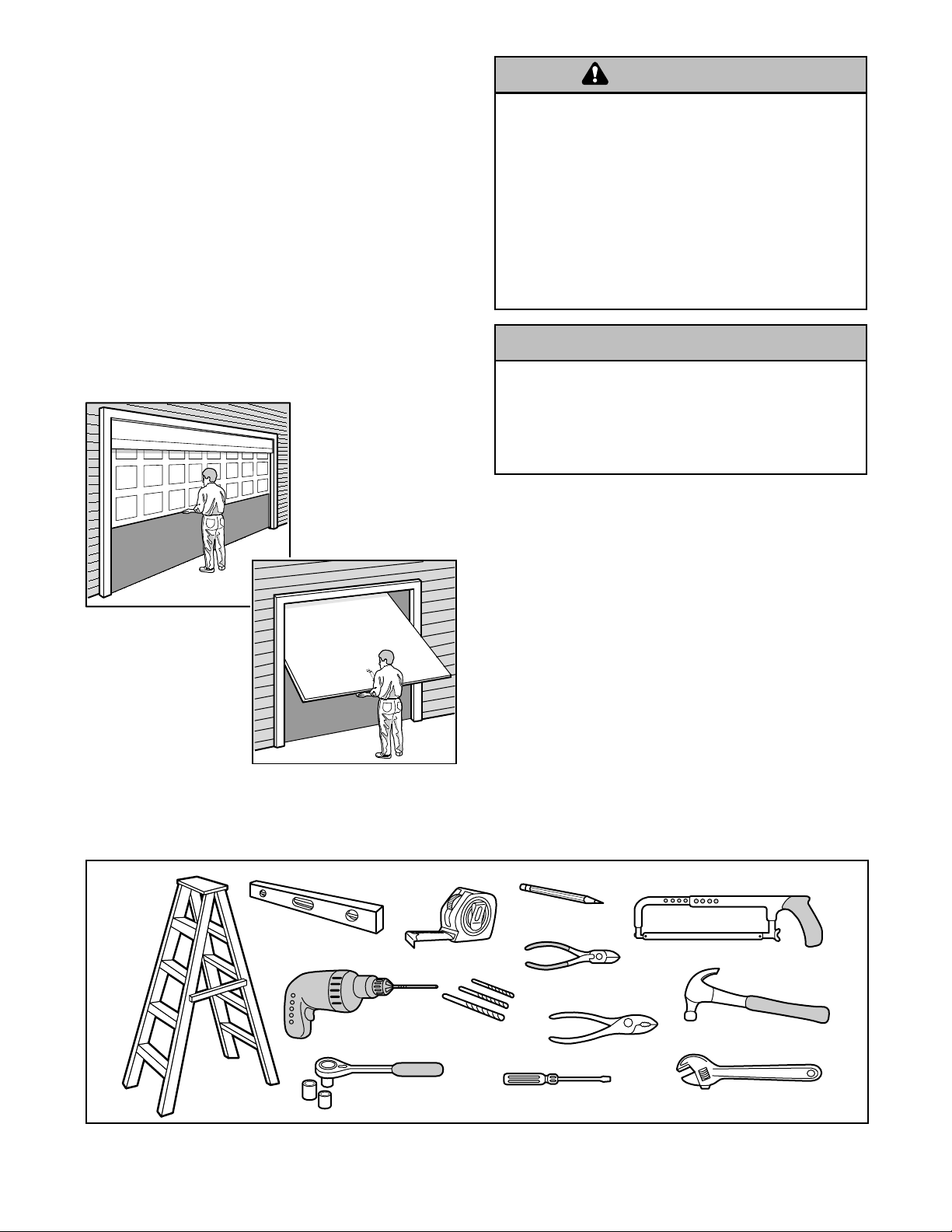
Preparing your garage door ........................................3
Tools needed...............................................................3
Planning .....................................................................4
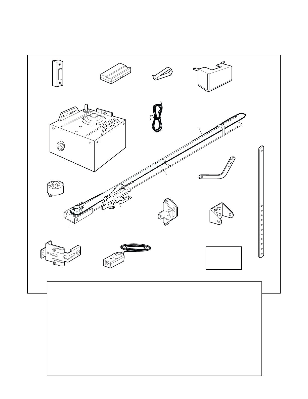
Car on inven ory..........................................................5
Hardware inven ory .....................................................5
Assembly 6-7
A ach he rail o he mo or uni ...................................6
A ach he chain o he sprocke ..................................6
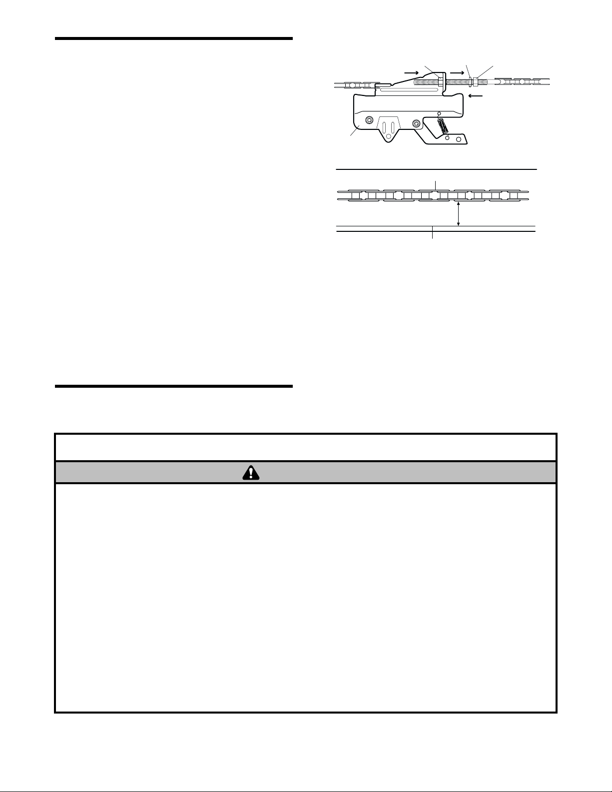
Tigh en he chain.........................................................7
Installation 7-23
Ins alla ion safe y ins ruc ions .....................................7
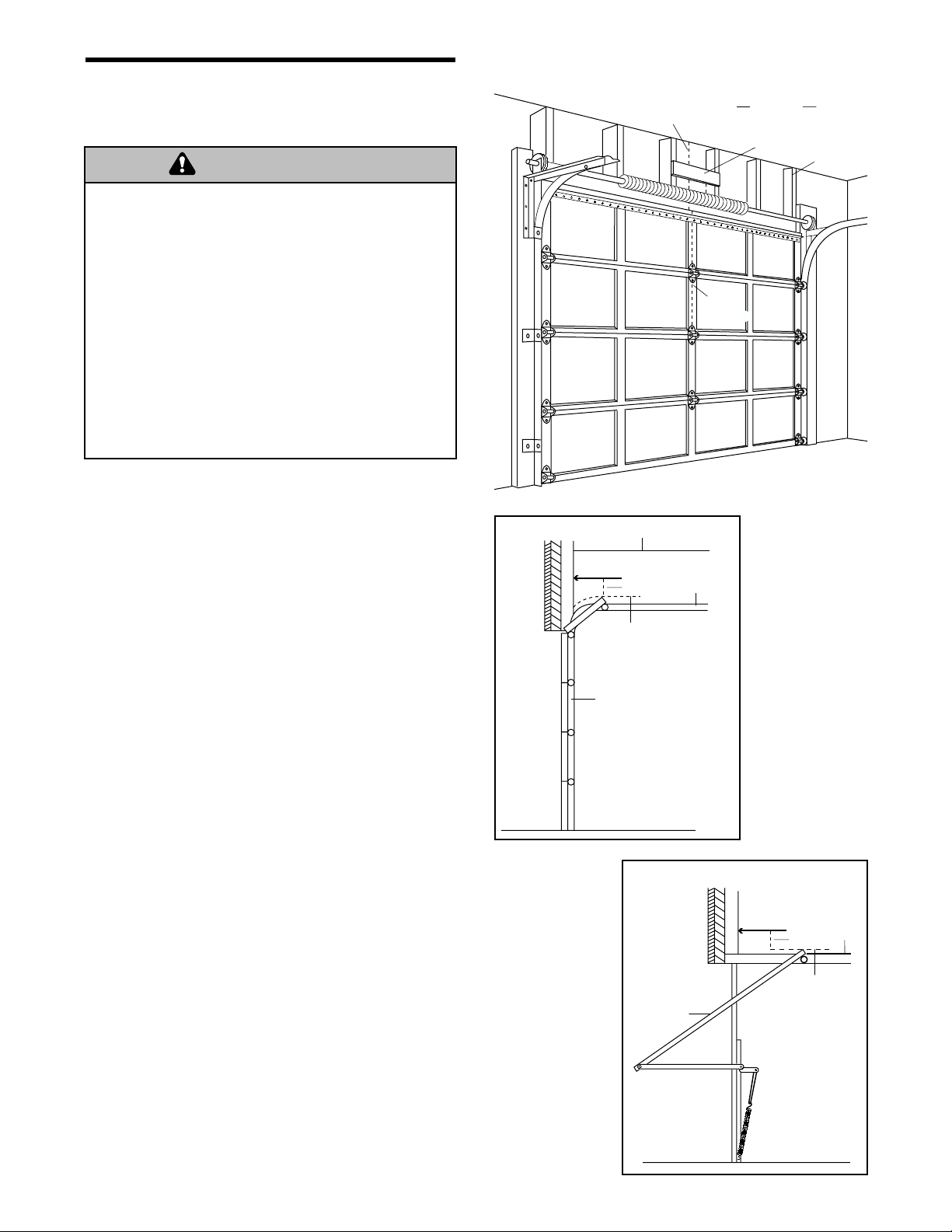
De ermine he header bracke loca ion....................8-9
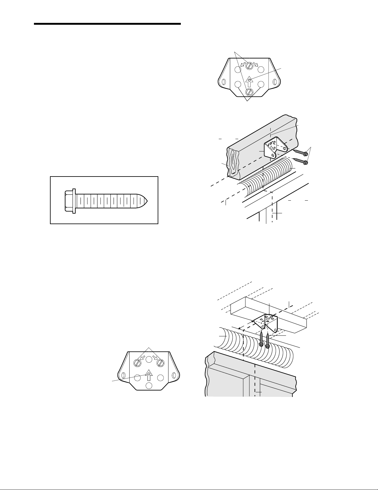
Ins all he header bracke ..........................................10
A ach he rail o he header bracke .........................11
Posi ion he opener ...................................................12
Hang he opener .......................................................13
Ins all he door con rol...............................................14
Ins all he ligh s .........................................................15
A ach he emergency release rope and handle .......15
Elec rical requiremen s..............................................16
Ins all he Pro ec or Sys em®................................17-19
Fas en he door bracke .......................................20-21
Connec he door arm o he rolley .....................22-23
Adjustment 24-26
Adjus he ravel limi s ...............................................24
Adjus he force .........................................................25
Tes he safe y reversal sys em.................................26
Tes he Pro ec or Sys em®........................................26
Operation 27-30
Opera ion safe y ins ruc ions.....................................27
Using your garage door opener ................................27
Using he wall-moun ed door con rol ........................28
To open he door manually........................................28
Care of your garage door opener..............................29
Having a problem?...............................................29-30
Programming 31-32
To add a hand-held remo e con rol ...........................31
To erase all codes .....................................................31
3-Channel remo es....................................................31
To add or change a Keyless En ry PIN.....................32
Repair Parts 33-34
Rail assembly par s...................................................33
Ins alla ion par s ........................................................33
Mo or uni assembly par s .........................................34
Accessories 35
Repair Parts and Service 36
Warranty 36
TABLE OF CONTENTS
When you see hese Safe y Symbols and Signal
Words on he following pages, hey will aler you o
he possibili y of serious injury or death if you do
no comply wi h he warnings ha accompany hem.
The hazard may come from some hing mechanical
or from elec ric shock. Read he warnings carefully.
When you see his Signal Word on he following
pages, i will aler you o he possibili y of damage o
your garage door and/or he garage door opener if
you do no comply wi h he cau ionary s a emen s
ha accompany i . Read hem carefully.
INTRODUCTION
Safety Symbol
and Signal Word Review
This garage door opener has been designed and es ed o offer safe service provided i is ins alled, opera ed,
main ained and es ed in s ric accordance wi h he ins ruc ions and warnings con ained in his manual.
Mechanical
Electrical
WARNING
CAUTION WARNING
WARNING
WARNING
CAUTION WARNING
WARNING
WARNING
CAUTION
WARNING
WARNING

3
To prevent damage to garage door and opener:
• ALWAYS disable locks BEFORE installing and operating
t e opener.
• ONLY operate garage door opener at 120V, 60 Hz to
avoid malfunction and damage.
To prevent possible SERIOUS INJURY OR DEATH:
• ALWAYS call a trained door systems tec nician if
garage door binds, sticks, or is out of balance. An
unbalanced garage door may not reverse w en
required.
• NEVER try to loosen, move or adjust garage door, door
springs, cables, pulleys, brackets or t eir ardware, all
of w ic are under EXTREME tension.
• Disable ALL locks and remove ALL ropes connected to
garage door BEFORE installing and operating garage
door opener to avoid entanglement.
Preparing your garage door
Before you begin:
• Disable locks.
• Remove any ropes connec ed o garage door.
•Complete the following test o make sure your
garage door is balanced and is no s icking or
binding:
1. Lif he door abou halfway as shown. Release
he door. If balanced, i should s ay in place,
suppor ed en irely by i s springs.
2. Raise and lower he door o see if here is any
binding or s icking.
If your door binds, s icks, or is ou of balance, call a
rained door sys ems echnician.
Tools needed
During assembly, ins alla ion and adjus men of he
opener, ins ruc ions will call for hand ools as
illus ra ed below.
WARNING
CAUTION WARNING
WARNING
WARNING
CAUTION
WARNING
WARNING
Pliers
Wire Cu ers
Claw Hammer
Hack Saw
Screwdriver Adjus able End Wrench
1/2" and 7/16" Socke s
and Wrench
Drill
Tape Measure
2
1
S epladder
Pencil
3/16", 5/16" and
5/32" Drill Bi s
Carpen er's
Level
Sectional Door
One-Piece Door

Safe y Reversing Sensor
Horizon al and ver ical reinforcemen
is needed for ligh weigh garage doors
(fiberglass, s eel, aluminum,
door wi h glass panels, e c.).
See page 20 for de ails.
FINISHED CEILING
Suppor bracke &
fas ening hardware
is required.
See page 13.
Mo or Uni
— — — — — — — —
Door
Cen er
Header Wall
Safe y
Reversing
Sensor
Gap be ween floor and bo om of door
mus no exceed 1/4"
Ex ension Spring
Torsion Spring
Access Door
OR
Slack in chain ension
is normal when
garage door is closed.
Wall-
moun ed
Door
Con rol
4
SECTIONAL DOOR INSTALLATION
Planning
Iden ify he ype and heigh of your garage door. Survey your garage area o see if any of he condi ions below
apply o your ins alla ion. Addi ional ma erials may be required. You may find i helpful o refer back o his page
and he accompanying illus ra ions as you proceed wi h he ins alla ion of your opener.
FINISHED CEILING
Suppor bracke
& fas ening
hardware is required.
See page 13.
Slack in chain ension
is normal when
garage door is closed.
Safe y
Reversing Sensor
Header
Wall
Access
Door
Safe y
Reversing Sensor
Gap be ween floor and bo om of
door mus no exceed 1/4"
Wall-
moun ed
Door
Con rol
Mo or Uni
ONE-PIECE DOOR WITHOUT TRACK
Access
Door
Safe y
Reversing Sensor
Safe y
Reversing
Sensor
Slack in chain ension is normal when
garage door is closed
Gap be ween floor
and bo om of door
mus no exceed 1/4"
ONE-PIECE DOOR WITH TRACK

5
S raigh Door
Arm Sec ion
Curved Door
Arm Sec ion
Safe y Labels
and
Li era ure
Header Bracke
UP
CEILING MOUNT ONLY
Sprocke Cover
2-Conduc or Bell Wire
Whi e & Whi e/Red
Ligh Lens (1)
Remo e Con rol
Visor Clip
Door Bracke
BuildMark
Single-Func ion
Remo e Con rol
Door Con rol Bu on
wi h (2) 6ABx1-1/2" screws
(2) Safe y Reversing Sensors
(1 Sending Eye and 1 Receiving Eye)
wi h 2-Conduc or Whi e &
Whi e/Black Bell Wire a ached
Safe y Sensor
Bracke (2)
One-Piece
Rail
Chain Pulley Bracke
Trolley
Chain
Mo or Uni
Your garage door opener is packaged in wo car ons
which con ain he mo or uni and all par s illus ra ed
below. Accessories will depend on he model
purchased. If any hing is missing, carefully check he
packing ma erial. Par s may be s uck in he foam.
Hardware for ins alla ion is also lis ed below.
Carton Inventory
INSTALLATION HARDWARE
Hex Bol 5/16"-18x7/8" (4)
Lag Screw 5/16"-9x1-5/8" (2)
Lag Screw 5/16"-18x1-7/8" (2)
Clevis Pin 5/16"x2-3/4" (1)
Clevis Pin 5/16"x1-1/4" (1)
Clevis Pin 5/16"x1" (1)
Nu 5/16"-18 (4)
Lock Washer 5/16" (4)
Screw 6ABx1-1/4" (2)
Screw 6-32x1" (2)
Self-Threading Screw 1/4"-14x5/8" (2)
Insula ed S aples (30)
Ring Fas ener (3)
Dry Wall Anchors (2)
Rail Grease
Carriage Bol 1/4"-20x1/2" (2)
Wing Nu 1/4”-20 (2)
Rope
Handle

6
ASSEMBLY STEP 1
Attach the Rail to the Motor Unit
To avoid installation difficulties, do not run the
garage door opener until instructed to do so.
• Remove he wo washered bol s moun ed in op of
mo or uni .
• Posi ion Rail a a 45˚ angle o opener so one hole
in Rail and mo or uni line up.
• Thread one of he washered bol s par way in.
Use only these bolts! Use of any other
bolts/fasteners will cause serious damage to
door opener.
• Align Rail over sprocke . Cu ape from Rail and
chain.
USE ONLY THIS
TYPE AND SIZE
BOLT Washered Bol
5/16"-18x1/2"
Rail
Hole
To avoid SERIOUS damage to opener, ONLY use
bolts/fasteners mounted in top of motor unit.
WARNING
CAUTION
WARNING
WARNING
ASSEMBLY STEP 2
Attach the Chain to the Sprocket
and Install the Sprocket Cover
• Posi ion chain over he sprocke . If necessary,
loosen he ou er nu on he rolley o ob ain more
chain slack.
• Inser he second washered bol . CAUTION: Use
only the bolt previously removed from motor
unit!
• Tigh en bo h bol s securely hrough he Rail in o
he mo or uni as shown.
• Ins all he sprocke cover: Inser he back ab in he
slo . Squeeze he cover sligh ly and inser he fron
ab in he slo on he moun ing pla e.
Proceed to Assembly Step 3.
To avoid possible SERIOUS INJURY to fingers from
moving garage door opener:
• ALWAYS keep and clear of sprocket w ile operating
opener.
• Securely attac sprocket cover BEFORE operating.
WARNING
CAUTION WARNING
WARNING
Washered Bol
5/16"-18x1/2"
Sprocke
Sprocke Cover
Moun ing
Pla e
Fron Tab Slo
Back Tab Slo
USE ONLY THIS
TYPE AND SIZE
BOLT

7
ASSEMBLY STEP 3
Tighten the Chain
• Spin he inner nu and lock washer down he
hreaded shaf , away from he rolley.
• To igh en he chain, urn ou er nu in he direc ion
shown. As you turn the nut, keep the chain
from twisting.
• When he chain is approxima ely 1/2" above he
base of he Rail a i s midpoin , re- igh en he inner
nu o secure he adjus men .
Sprocket noise can result if chain is either too
loose or too tight.
When ins alla ion is comple e, you may no ice some
chain droop wi h he door closed. This is normal. If
he chain re urns o he posi ion shown when he
door is open, do no re-adjus he chain.
NOTE During future maintenance, ALWAYS pull the
emergency release handle to disconnect trolley
before adjusting chain.
You have now finished assembling your garage
door opener. Please read the following warnings
before proceeding to the installation section.
Lock
Washer
To Tigh en Ou er Nu
Inner Nu
Trolley
Chain
Base of Rail
1/2 Inch
To Tigh en
Inner Nu
Ou er Nu
IMPORTANT INSTALLATION INSTRUCTIONS
1. READ AND FOLLOW ALL INSTALLATION WARNINGS
AND INSTRUCTIONS.
2. Install garage door opener only on properly balanced
and lubricated garage door. An improperly balanced
door may not reverse w en required and could result in
SEVERE INJURY or DEATH.
3. All repairs to cables, spring assemblies and ot er
ardware MUST be made by a trained door systems
tec nician BEFORE installing opener.
4. Disable all locks and remove all ropes connected to
garage door BEFORE installing opener to avoid
entanglement.
5. Install garage door opener 7 feet or more above floor.
6. Mount emergency release andle 6 feet above floor.
7. NEVER connect garage door opener to power source
until instructed to do so.
8. NEVER wear watc es, rings or loose clot ing w ile
installing or servicing opener. T ey could be caug t in
garage door or opener mec anisms.
9. Install wall-mounted garage door control:
• wit in sig t of t e garage door
• out of reac of c ildren at minimum eig t of 5 feet
• away from all moving parts of t e door.
10. Place entrapment warning label on wall next to garage
door control.
11. Place manual release/safety reverse test label in plain
view on inside of garage door.
12. Upon completion of installation, test safety reversal
system. Door MUST reverse on contact wit a one-
inc ig object (or a 2x4 laid flat) on t e floor.
To reduce the risk of severe injury or death:
WARNING
WARNING
INSTALLATION

8
INSTALLATION STEP 1
Determine the Header Bracket
Location
Ins alla ion procedures vary according o garage door
ypes. Follow he ins ruc ions which apply o your
door.
SECTIONAL DOOR
AND ONE-PIECE DOOR WITH TRACK
1. Close he door and mark he inside ver ical
cen erline of he garage door.
2. Ex end he line on o he header wall above he
door.
You can fasten the header bracket within 4 feet
of the left or right of the door center only if a
torsion spring or center bearing plate is in the
way; or you can attach it to the ceiling (see
page 10) when clearance is minimal. (It may be
mounted on the wall upside down if necessary,
to gain approximately 1/2".)
If you need o ins all he header bracke on a 2x4
(on wall or ceiling), use lag screws (no provided)
o securely fas en he 2x4 o s ruc ural suppor s as
shown here and on page 10.
3. Open your door o he highes poin of ravel as
shown. Draw an in ersec ing horizon al line on he
header wall 2" above he high poin . This heigh
will provide ravel clearance for he op edge of he
door.
Proceed to Step 2, page 10. One-piece
door with
horizontal
track
To prevent possible SERIOUS INJURY or DEATH:
• Header bracket MUST be RIGIDLY fastened to
structural support on eader wall or ceiling, ot erwise
garage door mig t not reverse w en required. DO NOT
install eader bracket over drywall.
• Concrete anc ors MUST be used if mounting eader
bracket or 2x4 into masonry.
• NEVER try to loosen, move or adjust garage door,
springs, cables, pulleys, brackets, or t eir ardware, all
of w ic are under EXTREME tension.
• ALWAYS call a trained door systems tec nician if
garage door binds, sticks, or is out of balance. An
unbalanced garage door mig t not reverse w en
required.
Header Wall
Ceiling
Track
Highes Poin
of Travel
Door
2"
Sectional door
with curved
track
Door
Track
Header Wall
Highes Poin
of Travel
2"
Finished
Ceiling
Ver ical
Cen erline
Header
Wall 2x4 S ruc ural
Suppor s
Ver ical
Cen erline
WARNING
CAUTION WARNING
WARNING

9
Header Wall Ver ical
Cen erline
Ver ical
Cen erline
of Garage
Door
2x4
Unfinished
Ceiling
2x4
OPTIONAL
CEILING MOUNT
OR
HEADER BRACKET
S ruc ural
Suppor s
ONE-PIECE DOOR WITHOUT TRACK
1. Close he door and mark he inside ver ical
cen erline of your garage door. Ex end he line
on o he header wall above door, as shown.
If headroom clearance is minimal, you can ins all
he header bracke on he ceiling. See page 10.
If you need o ins all he header bracke on a 2x4
(on wall or ceiling), use lag screws (no provided)
o securely fas en he 2x4 o s ruc ural suppor s
as shown.
2. Open your door o he highes poin of ravel as
shown. Measure he dis ance from he op of he
door o he floor. Sub rac he ac ual heigh of he
door. Add 8" o he remainder. (See Example).
3. Close he door and draw an in ersec ing horizon al
line on he header wall a he de ermined heigh .
NOTE If the total number of inches exceeds the
height a ailable in your garage, use the maximum
height possible, or refer to page 10 for ceiling
installation.
Door
Highes Poin
of Travel
Header Wall
Pivo
Dis ance
Floor
One-piece door without track:
pivot hardware
Header Wall
Highes Poin
of Travel
Door
Floor
Dis ance
Jamb
Hardware
One-piece door without track:
jamb hardware
EXAMPLE
Dis ance from op of door
(a highes poin of ravel) o floor ...................... 92"
Ac ual heigh of door .......................................... -88"
Remainder.......................................................... 4"
Add..................................................................... +8"
Bracke heigh on header wall............................ =12"
(Measure UP from op of CLOSED door.)
Proceed to Step 2, page 10.

10
INSTALLATION STEP 2
Install the Header Bracket
You can a ach he header bracke ei her o he wall
above he garage door, or o he ceiling. Follow he
ins ruc ions which will work bes for your par icular
requiremen s. Do not install the header bracket
over drywall. If installing into masonry, use
concrete anchors (not provided).
WALL HEADER BRACKET INSTALLATION
• Cen er he bracke on he ver ical cen erline wi h
he bo om edge of he bracke on he horizon al
line as shown (wi h he arrow poin ing oward he
ceiling).
• Mark he ver ical se of bracke holes (do no use
he holes designa ed for ceiling moun ). Drill 3/16"
pilo holes and fas en he bracke securely o a
s ruc ural suppor wi h he hardware provided.
Lag Screw
5/16"-9 x 1-5/8"
HARDWARE SHOWN ACTUAL SIZE
Lag Screws
5/16"-9x1-5/8"
Highes Poin of
Garage Door Travel
Ver ical
Cen erline
Header
Wall
Garage
Door
UP
CEILING MOUNT ONLY
Wall Moun ing Holes
Op ional
Wall Moun ing Holes
The nail hole is for
posi ioning only.
You mus use lag screws
o moun he header bracke .
UP
CEILING MOUNT ONLY
Door Spring
Header
Bracke
2x4
S ruc ural
Suppor
Ver ical
Cen erline
UP
CEILING MOUNT ONLY
Ceiling Moun ing Holes
The nail hole is for
posi ioning only.
You mus use lag screws
o moun he header bracke .
UP
Lag Screws
5/16"-9x1-5/8"
Garage Door
Ver ical Cen erline
Header Wall
– inished Ceiling –
Header
Bracke
6" Maximum
Ver ical
Cen erline
Door
Spring
CEILING HEADER BRACKET INSTALLATION
• Ex end he ver ical cen erline on o he ceiling as
shown.
• Cen er he bracke on he ver ical mark, no more
han 6" from he wall. Make sure he arrow is
poin ing oward he wall. The bracke can be
moun ed flush agains he ceiling when clearance
is minimal.
• Mark he side holes. Drill 3/16" pilo holes and
fas en bracke securely o a s ruc ural suppor wi h
he hardware provided.

Clevis Pin
5/16"x2-3/4" Ring Fastener
11
INSTALLATION STEP 3
Attach the Rail to the Header
Bracket
• Position the opener on the garage floor belo the
header bracket. Use packing material as a
protective base. NOTE: If the door spring is in the
way you’ll need help. Have someone hold the
opener securely on a temporary support to allow
the Rail to clear the spring.
• Position the rail bracket against the header
bracket.
• Align the bracket holes and join ith a clevis pin
as sho n.
• Insert a ring fastener to secure.
Header
Bracket
Chain
Pulley
Bracket
Temporary
Support
Header Wall
Garage
Door
Rail
Clevis Pin
5/16"x2-3/4"
Ring Fastener
Header Bracket
Chain
Pulley
Bracket
Rail
Motor Unit
HARDWARE SHOWN ACTUAL SIZE

12
ONE-PIECE DOOR WITHOUT TRACK
• With the door fully open and parallel to the floor,
measure the distance from the floor to the top of
the door.
• Using a stepladder as a support, raise the top of
the opener to this height.
• The top of the door should be level ith the top of
the motor unit. Do not position the opener more
than 2" above this point.
INSTALLATION STEP 4
Position the Opener
Follo instructions hich apply to your door type as
illustrated.
SECTIONAL DOOR OR ONE-PIECE DOOR WITH
TRACK
A 2x4 laid flat is convenient for setting an ideal door-
to-Rail distance.
• Raise the opener onto a stepladder. You ill need
help at this point if the ladder is not tall enough.
• Open the door all the ay and place a 2x4 laid flat
on the top section beneath the Rail.
• If the top section or panel hits the trolley hen you
raise the door, pull do n on the trolley release arm
to disconnect inner and outer sections. Slide the
outer trolley to ard the motor unit. The trolley can
remain disconnected until Installation Step 12
is completed.
Rail 2x4
Door
Stepladder
Trolley
Release Arm
ENGAGED RELEASED
To prevent damage to garage door, rest garage door
opener Rail on 2x4 placed on top section of door.
WARNING
CAUTION
WARNING
WARNING
Top of Motor Unit
Header
Bracket
Stepladder
Top of Door

13
INSTALLATION STEP 5
Hang the Opener
T o representative installations are sho n. Yours
may be different. Hanging brackets should be angled
(Figure 1) to provide rigid support. On finished
ceilings (Figure 2), attach a sturdy metal bracket to
structural supports before installing the opener. This
bracket and fastening hard are are not provided.
1. Remove foam packaging. Measure the distance
from each side of the motor unit to the structural
support.
2. Cut both pieces of the hanging bracket to required
lengths.
3. Drill 3/16" pilot holes in the structural supports.
4. Attach one end of each bracket to a support ith
5/16"-18x1-7/8" lag scre s.
5. Fasten the opener to the hanging brackets ith
5/16"-18x7/8" hex bolts, lock ashers and nuts.
6. Check to make sure the Rail is centered over the
door (or in line ith the header bracket if the
bracket is not centered above the door).
7. Remove the 2x4. Operate the door manually. If the
door hits the Rail, raise the header bracket.
8. Grease the top and underside of the Rail surface
here the trolley slides ith rail grease.
To avoid possible SERIOUS IN URY from a falling
garage door opener, fasten it SECURELY to structural
supports of the garage. Concrete anchors MUST be used
if installing any brackets into masonry.
Lag Scre 5/16"-18x1-7/8"
Hex Bolt
5/16"-18x7/8" Nut 5/16"-18 Lock Washer 5/16"
HARDWARE SHOWN ACTUAL SIZE
Measure
Distance
Lag Scre s
5/16"x1-7/8"
Bracket
(Not Provided)
Lag Scre s
5/16"x1-7/8"
(Not Provided)
Bolt 5/16"-18x7/8"
Lock Washer 5/16"
Nut 5/16"-18
— FINISHED CEILING —
Structural
Supports
Bolt 5/16"-18x7/8"
Lock Washer 5/16"
Nut 5/16"-18
Bolt 5/16"-18x7/8"
Lock Washer 5/16"
Nut 5/16"-18
Hidden
Support
Figure 1
Figure 2
WARNING
CAUTION WARNING
WARNING

14
INSTALLATION STEP 6
Install the Door Control
Locate door control ithin sight of the door at a
minimum height of 5 feet here small children
cannot reach, and a ay from moving parts of the
door and door hard are. If installing into dry all drill
5/32” holes and use the anchors provided.
1. Strip 1/4" of insulation from one end of bell ire
and connect to the t o scre terminals on back of
door control by color: hite ire to 2 and hite/red
ire to 1.
2. Run bell ire up all and across ceiling to motor
unit. Use insulated staples to secure ire in
several places. Do not pierce ire ith a staple,
creating a short or open circuit.
3. Connect bell ire to the opener terminal scre s as
follo s: hite to 2 and hite/red to 1.
4. Use tacks or staples to permanently attach
entrapment arning label to all near door control,
and manual release/safety reverse test label in a
prominent location on inside of garage door.
NOTE: DO NOT connect the power and operate the
opener at this time. The trolley will travel to the full
open position but will not return to the close position
until the sensor beam is connected and properly
aligned. ee afety Reversing ensor Instructions
beginning on page 17.
Dry Wall Anchors Insulated
Staples
Scre 6ABx1-1/2"
Lighted Door Control Button
HARDWARE SHOWN ACTUAL SIZE
To prevent possible SERIOUS IN URY or DEATH from
electrocution:
• Be sure power is not connected BEFORE installing door
control.
• Connect only to 24 VOLT low voltage wires.
To prevent possible SERIOUS IN URY or DEATH from a
closing garage door:
• Install door control within sight of garage door, out of
reach of children at a minimum height of 5 feet, and
away from all moving parts of door.
• NEVER permit children to operate or play with door
control push buttons or remote control transmitters.
• Activate door only when it can be seen clearly, is
properly adjusted, and there are no obstructions to door
travel.
• ALWAYS keep garage door in sight until completely
closed. NEVER permit anyone to cross path of closing
garage door.
WARNING
CAUTION
WARNING
WARNING
ATTENTION
AVERTISSEMENT AVERTISSEMENT
AVERTISSEMENT
2-Conductor
Bell Wire
Door
Control
Terminal
Scre s
2-Conductor
Bell Wire
WHT
2
RED
1
Door Control
Button
Opener
Terminal
Scre s
Antenna
Back Panel
of Opener
K
G
K
G
1
9
7
5
1
9
7
5
2
1

15
INSTALLATION STEP 7
Install the Light and Lens
INSTALL THE LIGHT
• Install a 75 att maximum light bulb in the socket.
The light ill turn ON and remain lit for
approximately 4-1/2 minutes hen po er is
connected. Then the light ill turn OFF.
• If the bulb burns out prematurely due to vibration,
replace ith a Garage Door Opener bulb.
INSTALL THE LENS
• Locate and loosen (approximately 1/8") the t o
scre s near top of opener front panel. Position lens
against panel ith slotted tabs directly belo
scre s. Slide lens up to seat tabs behind scre s.
Snap bottom tabs of lens into panel slots. Retighten
top panel scre s to secure lens.
INSTALLATION STEP 8
Attach the Emergency Release
Rope and Handle
• Thread one end of the rope through the hole in the
top of the red handle so "NOTICE" reads right side
up as sho n. Secure ith an overhand knot at
least 1" from the end of the rope to prevent
slipping.
• Thread the other end of the rope through the hole
in the release arm of the outer trolley.
• Adjust rope length so the handle is 6 feet above
the floor. Secure ith an overhand knot.
NOTE: If it is necessary to cut the rope, heat seal
the cut end with a match or lighter to prevent
unraveling.
• To prevent possible SERIOUS IN URY or DEATH from
a falling garage door:
– If possible, use emergency release handle to
disengage trolley ONLY when garage door is
CLOSED. Weak or broken springs or unbalanced
door could result in an open door falling rapidly
and/or unexpectedly.
– NEVER use emergency release handle unless garage
doorway is clear of persons and obstructions.
• NEVER use handle to pull door open or closed. If rope
knot becomes untied, you could fall.
Trolley
NOTICE
Overhand
Knot
Emergency
Release Handle
Rope
Trolley
Release Arm
WARNING
CAUTION WARNING
WARNING
Lens Slot
75 Watt Max.
Light Bulb
Lens Tab
Light
Lens
Panel Scre

16
INSTALLATION STEP 9
Electrical Requirements
To avoid installation difficulties, do not run the
opener at this time.
To reduce the risk of electric shock, your garage door
opener has a grounding type plug ith a third
grounding pin. This plug ill only fit into a grounding
type outlet. If the plug doesn't fit into the outlet you
have, contact a qualified electrician to install the
proper outlet.
If permanent wiring is required by your local
code, refer to the following procedure.
To make a permanent connection through the 7/8"
hole in the top of the motor unit:
• Remove the motor unit cover scre s and set the
cover aside.
• Remove the attached 3-prong cord.
• Connect the black (line) ire to the scre on the
brass terminal; the hite (neutral) ire to the
scre on the silver terminal; and the ground ire
to the green ground scre . The opener must be
grounded.
• Reinstall the cover.
To avoid installation difficulties, do not run the
opener at this time.
RIGHT WRONG
To prevent possible SERIOUS IN URY or DEATH from
electrocution or fire:
• Be sure power is not connected to the opener, and
disconnect power to circuit BEFORE removing cover to
establish permanent wiring connection.
• Garage door installation and wiring MUST be in
compliance with all local electrical and building codes.
• NEVER use an extension cord, 2-wire adapter, or
change plug in ANY way to make it fit outlet. Be sure
the opener is grounded.
Ground Tab
Green
Ground Scre
Ground Wire
Black Wire
PERMANENT WIRING
CONNECTION
White Wire
Black
Wire
WARNING
CAUTION WARNING
WARNING

17
Invisible Light Beam
Protection Area
Sensor Beam
6" max.
above floor
Sensor Beam
6" max.
above floor
Facing the door from inside the garage
INSTALLATION STEP 10
Install The Protector System®
The safety reversing sensor must be connected
and aligned correctly before the garage door
opener will move in the down direction.
IMPORTANT INFORMATION ABOUT
THE SAFETY REVERSING SENSOR
When properly connected and aligned, the sensor
ill detect an obstacle in the path of its electronic
beam. The sending eye ( ith an orange indicator
light) transmits an invisible light beam to the
receiving eye ( ith a green indicator light). If an
obstruction breaks the light beam hile the door is
closing, the door ill stop and reverse to full open
position, and the opener lights ill flash 10 times.
The units must be installed inside the garage so that
the sending and receiving eyes face each other
across the door, no more than 6" above the floor.
Either can be installed on the left or right of the door
as long as the sun never shines directly into the
receiving eye lens.
The mounting brackets are designed to clip onto the
track of sectional garage doors ithout additional
hard are.
If it is necessary to mount the units on the all, the
brackets must be securely fastened to a solid
surface such as the all framing. Extension brackets
(see accessories) are available if needed. If
installing in masonry construction, add a piece of
ood at each location to avoid drilling extra holes in
masonry if repositioning is necessary.
The invisible light beam path must be unobstructed.
No part of the garage door (or door tracks, springs,
hinges, rollers or other hard are) may interrupt the
beam hile the door is closing.
• Be sure power is not connected to the garage door
opener BEFORE installing the safety reversing sensor.
• To prevent SERIOUS IN URY or DEATH from a closing
garage door:
– Correctly connect and align the safety reversing
sensor. This required safety device MUST NOT be
disabled.
– Install the safety reversing sensor so beam is NO
HIGHER than 6" above garage floor.
WARNING
CAUTION WARNING
WARNING

18
FLOOR MOUNT (RIGHT SIDE)
WALL MOUNT (RIGHT SIDE)
DOOR TRACK MOUNT (RIGHT SIDE)
Indicator
light
Lens
Lip
Sensor
Bracket
Door
Track
Sensor
Bracket
Extension
Bracket
(See Accessories)
Lens
Indicator
light
Attach ith
concrete anchors
(not provided)
Inside
Garage
Wall
Indicator
light
Sensor
Bracket
Lens
Extension
Bracket
(See Accessories)
Inside
Garage
Wall
(Provided ith
Extension
Bracket)
(Provided ith
Extension Bracket)
(Provided ith
Extension
Bracket)
(Provided ith
Extension Bracket)
Figure
Figure 1
Figure 2
INSTALLING THE BRACKETS
Be sure power to the opener is disconnected.
Install and align the brackets so the sensors ill face
each other across the garage door, ith the beam no
higher than 6" above the floor. They may be installed
in one of three ays, as follo s.
Garage door track installation (preferred):
• Slip the curved arms over the rounded edge of
each door track, ith the curved arms facing the
door. Snap into place against the side of the track.
It should lie flush, ith the lip hugging the back
edge of the track, as sho n in Figure 1.
If your door track ill not support the bracket
securely, all installation is recommended.
Wall installation:
• Place the bracket against the all ith curved
arms facing the door. Be sure there is enough
clearance for the sensor beam to be unobstructed.
• If additional depth is needed, an extension bracket
(see Accessories) or ood blocks can be used.
• Use bracket mounting holes as a template to
locate and drill (2) 3/16" diameter pilot holes on
the all at each side of the door, no higher than 6"
above the floor.
• Attach brackets to all ith lag scre s
(not provided).
• If using extension brackets or ood blocks, adjust
right and left assemblies to the same distance out
from the mounting surface. Make sure all door
hard are obstructions are cleared.
Floor installation:
• Use ood blocks or extension brackets (see
Accessories) to elevate sensor brackets so the
lenses ill be no higher than 6" above the floor.
• Carefully measure and place right and left
assemblies at the same distance out from the all.
Be sure all door hard are obstructions are
cleared.
• Fasten to the floor ith concrete anchors as
sho n.
Wing Nut
1/4"-20 Staples
Carriage Bolt
1/4"-20x1/2"
HARDWARE SHOWN ACTUAL SIZE

19
Carriage bolt
1/4"-20x1/2" Lens
Wing nut
MOUNTING AND WIRING THE SAFETY SENSORS
• Slide a 1/4"-20x1/2" carriage bolt head into the slot
on each sensor. Use ing nuts to fasten sensors to
brackets, ith lenses pointing to ard each other
across the door. Be sure the lens is not obstructed
by a bracket extension (Figure 4.)
• Finger tighten the ing nuts.
• Run the ires from both sensors to the opener. Use
insulated staples to secure ire to all and ceiling.
• Strip 1/4" of insulation from each set of ires.
Separate hite and hite/black ires sufficiently to
connect to the opener terminal scre s: hite to 2
and hite/black to 3 (Figure 5.)
ALIGNING THE SAFETY SENSORS
• Plug in the opener. The indicator lights in both the
sending and receiving eyes ill glow steadily if
iring connections and alignment are correct.
The sending eye orange indicator light ill glo
regardless of alignment or obstruction. If the green
indicator light in the receiving eye is off, dim, or
flickering (and the invisible light beam path is not
obstructed), alignment is required.
• Loosen the sending eye ing nut and readjust,
aiming directly at the receiving eye. Lock in place.
• Loosen the receiving eye ing nut and adjust
sensor until it receives the sender’s beam. When
the green indicator light glo s steadily, tighten the
ing nut.
TROUBLESHOOTING THE SAFETY SENSORS
1. If the sending eye indicator light does not glo
steadily after installation, check for:
• Electric po er to the opener.
• A short in the hite or hite/black ires. These
can occur at staples, or at scre terminal
connections.
• Incorrect iring bet een sensors and opener.
• A broken ire.
2. If the sending eye indicator light glo s steadily but
the receiving eye indicator light doesn't:
• Check alignment.
• Check for an open ire to the receiving eye.
3. If the receiving eye indicator light is dim, realign
either sensor.
NOTE: When the invisible beam path is obstructed
or misaligned while the door is closing, the door will
reverse. If the door is already open, it will not close.
The opener lights will blink 10 times. (If bulbs are not
installed, 10 clicks can be heard.) ee page 17.
Invisible Light Beam
Protection Area
Sensor
Sensor
Connect Wire to
Opener Terminal Scre s
Bell Wire
Bell Wire Finished
Ceiling
OPENER TERMINAL SCREWS
Sensor
Connection
s
Door Control
Connections
(dotted line)
12
Figure 4
Figure 5

20
INSTALLATION STEP 11
Fasten the Door Bracket
Follo instructions hich apply to your door type
as illustrated belo or on the follo ing page.
A horizontal reinforcement brace should be long
enough to be secured to two or three vertical
supports. A vertical reinforcement brace should
cover the height of the top panel.
Figure 1 sho s one piece of angle iron as the
horizontal brace. For the vertical brace, 2 pieces of
angle iron are used to create a U-shaped support.
The best solution is to check ith your garage door
manufacturer for an opener installation door
reinforcement kit.
NOTE: Many door reinforcement kits provide for
direct attachment of the clevis pin and door arm. In
this case you will not need the door bracket; proceed
to tep 12.
SECTIONAL DOORS
1. Center the door bracket on the previously marked
vertical centerline used for the header bracket
installation. Note correct UP placement, as
stamped inside the bracket.
2. Position the top edge of the bracket 2"-4" belo
the top edge of the door, OR directly belo any
structural support across the top of the door.
3. Mark, drill holes and install as follo s, depending
on your door’s construction:
Metal or light weight doors using a vertical angle
iron race etween the door panel support and
the door racket:
• Drill 3/16" fastening holes. Secure the door bracket
using the t o 1/4"-14x5/8" self-threading scre s.
(Figure 2A)
• Alternately, use t o 5/16" bolts, lock ashers and
nuts (not provided). (Figure 2B)
Metal, insulated or light weight factory reinforced
doors:
• Drill 3/16" fastening holes. Secure the door bracket
using the self-threading scre s (Figure 3).
Wood Doors:
• Use top and bottom or side to side door bracket
holes. Drill 5/16" holes through the door and
secure bracket ith 5/16"x2" carriage bolts, lock
ashers and nuts (not provided). (Figure 4)
NOTE: The 1/4"-14x5/8"
self-threading screws are
not intended for use on
wood doors.
To prevent damage to garage door, reinforce inside of
door with angle iron both vertically and horizontally.
WARNING
CAUTION
WARNING
WARNING
Vertical
Centerline
Door
Bracket
Location
Header
Bracket
HORIZONTAL AND VERTICAL
REINFORCEMENT IS NEEDED
FOR LIGHTWEIGHT GARAGE
DOORS (FIBERGLASS,
ALUMINUM, STEEL, DOORS
WITH GLASS PANEL, ETC).
(NOT PROVIDED)
Door
Bracket
Vertical
Centerline
UP
Vertical
Reinforcement
Self-Threading
Scre
1/4"-14x5/8"
Door
Bracket
Nut
5/16"-18
Bolt
5/16"-18x2"
Lock Washer
5/16"
Vertical
Centerline
UP
Vertical
Reinforcement
(Not Provided)
UP
Vertical
Centerline
Self-Threading
Scre
1/4"-14x5/8"
UP
Inside Edge
of Door or
Reinforcement Board
Bolt
5/16"x2"
Vertical
Centerline
(Not Provided)
Figure 1
Figure 2A
Figure 2B
Figure
Figure 4
Self-Threading
Scre
1/4"-14x5/8"
HARDWARE
SHOWN
ACTUAL SIZE
This manual suits for next models
1
Table of contents
Other BuildMark Garage Door Opener manuals
Popular Garage Door Opener manuals by other brands

Chamberlain
Chamberlain Grifco CG3800 instruction manual

Chamberlain
Chamberlain Power Drive 182638D owner's manual

Genie
Genie 2042 installation manual

Chase Doors
Chase Doors DuraShield installation manual

Chamberlain
Chamberlain Elite 3575S owner's manual

Automatic Technology
Automatic Technology Dominator AM800 instruction manual

Chamberlain
Chamberlain 4000 instructions

Optex
Optex PROSWING OA-EDGE T Original instructions

Beninca
Beninca MS4 Operating instructions and spare parts catalogue

Chamberlain
Chamberlain 8550 user manual

Craftsman
Craftsman 139.53982SRT owner's manual

Genie
Genie Screw Drive Assembly/installation instructions