Seite 9 / 12
Carefully collect them so that
they can not get lost. Pay
attention to reassemble
them in the right manner.
7.3.4 Lower walls
All lower separation walls
can be vertically pulled out
from the machine body. Prior to doing so, all
upper rollers must have been removed and the
belt must have been loosened.
7.3.5 Gear Belt
Easing the gear belt and demounting the down-
holder were already discussed in 7.3.3 (lower
transportation rolls). Here now the description of
the remaining tasks to do to remove the belt com-
pletely. After demounting the lower walls, the slit
pipe, in which the gear belt runs, can be pressed
from the lateral mounting plates to the center of
the machine. Particularly consider when re-in-
stalling the pipe that it must lie with the slit side
downward, in order to prevent leaking of etching
agent into the rinsing zone. In the discharge zone
the gear belt runs in a loop by two recesses of a
cover plate. The cover plate is levered off, if ne-
cessary with help of a screwdriver, upward and
removed. Under the cover one sees the connec-
tion to the gear motor. To remove the gear belt,
loosen two attachments screws of the gear mo-
tor. Move the gear motor until you can take out
the gear belt.
Caution! Do not bend the
a is of the gear motor.
The engine must be
fastened right after remov-
ing the gear belt again.
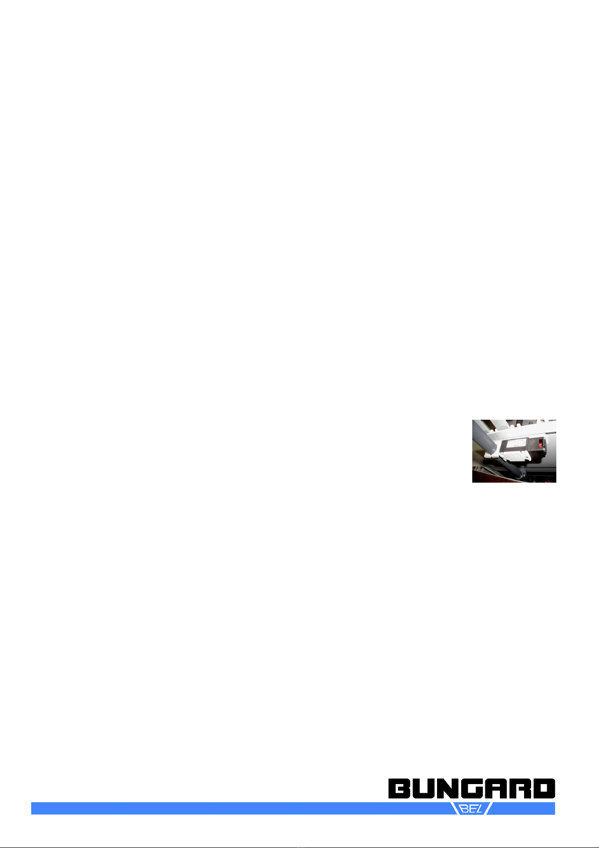
The gear belt together
with the slit pipe can now
be taken out of the ma-
chine (14). In order to remove it from the pipe, e -
pand the pipe by hand at an end a little slit the
pipe between two teeth of the gear belt. The con-
dition of the gear belt should be e amined with
each cleaning or disassembly of the machine.
Possible etching agent deposits must be re-
moved, since they can effect the operation
smoothness.
The gear belt tension changes normally only
slightly. A sudden, larger change of the belts ten-
sion points possibly to a wrong assembly of the
transportation rolls or the downholder. The two
first clamp blocks in the feeding zone of the ma-
chine possess adjusting screws for stretching the
belt. The screws must be adjusted parallel. A
loose gear belt is likely to slip over the rolls. This
becomes apparent in clear crack noises and
leads to uneven etching results and increased
wear of the drive components. A sufficient ten-
sion of the belt is given, if the first transport roles
are slightly movable in longitudinal direction.
Avoid a too high tension of the belt.
If the gear belt is properly adjusted and still not all
roles run evenly, check first if the fleeces are
clamped and if all upper rolls lie on the lower
roles. In the second step e amine the free move-
ment of the downholders. If necessary the pres-
sure of the downholders on the gear belt can be
varied adjusting the grub screws on top of the
holders.
7.4 Manifolds
Important: The upper and lower manifolds have
different length and nozzle equipment. They must
under no circumstances be interchanged. The
manifolds are fi ed in snap-in brackets. To re-
move them, pull them forward until they come
free from the fitting connectors and then carefully
lift them from the brackets. The nozzles are fi ed
to the manifold tubes also by a simple snap-in
system. You may use a pair of pliers to carefully
turn and twist the nozzles off.
Do not use screw drivers or similar! Damage
would result.
To reassemble the manifolds, insert the nozzles
manually. You may put them one by one on a
table with the flat side down and then press the
manifold tube on the nozzle until it snaps in. The
nozzle slots must all be aligned parallel to the
manifold tube a is.
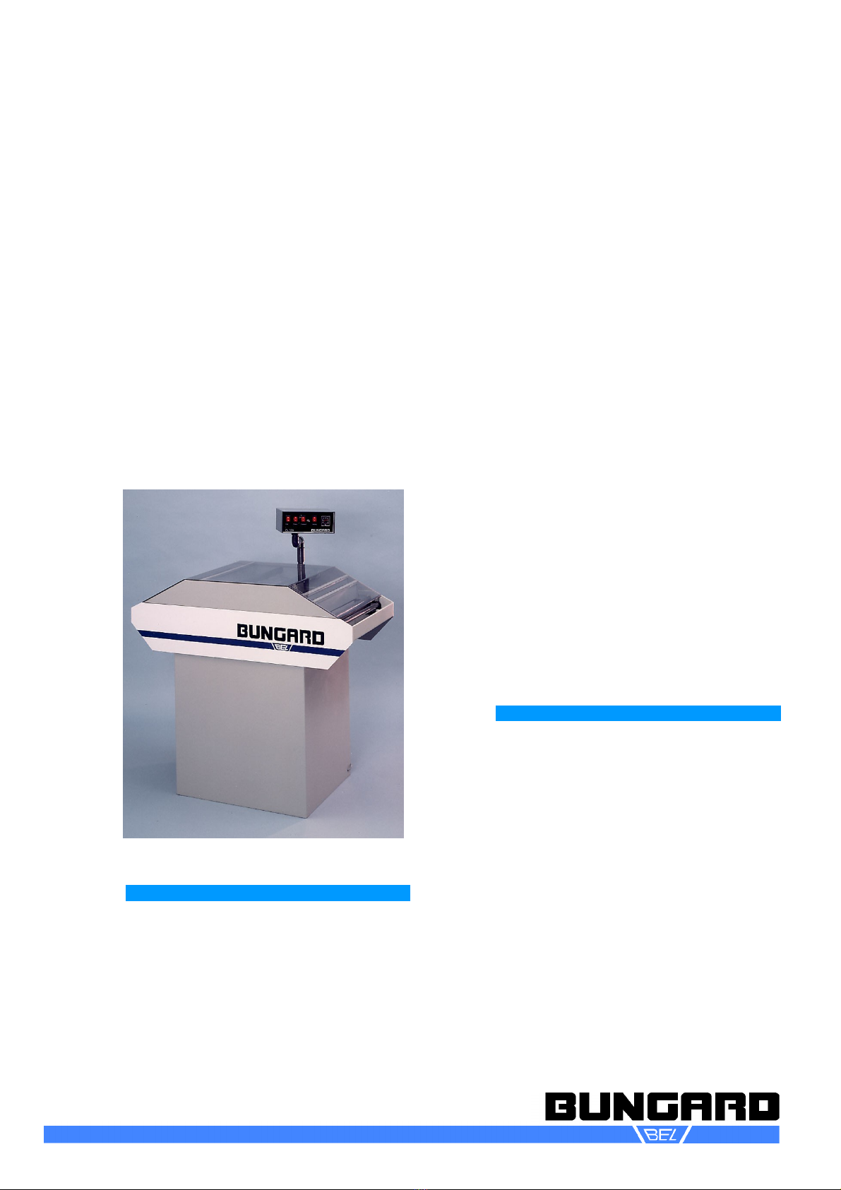
DL 500
Etching Machine
Instructions for Use
(13)
(14)
Bungard Elektronik GmbH & Co. KG, Rilkestraße 1, 51570 Windeck – Germany
Tel.: +49 (0) 2292/5036, Fa : +49 (0) 2292/6175, E-mail: support@bungard.de