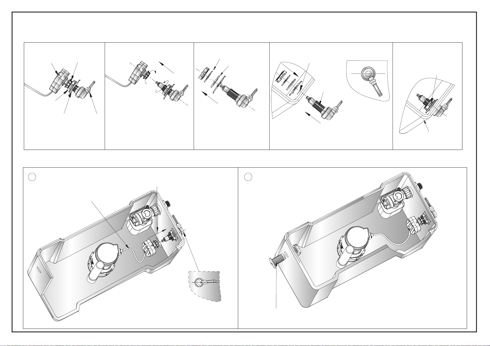
Burlington C5 User manual

A
1 - 1
High Level Cistern C5
Half flush float
Should be set on the "2"
mark
Half flush adjustor
Full flush adjustor Should be set on
the "2.25" mark
Should be set on the "1.75" mark
Note:
The Flush Valve can be adjusted to suit the High Level Cistern - C5.
The valve is preset for 6L full flush and 3L half flush.
The above diagram indicates the correct setting for 4.5L full flush and 2.6L half flush.
For adjustment method, please refer to the installation instruction supplied with the cistern fittings.
75mm
Note:
The Inlet Valve can be adjusted to suit the
High Level Cistern - C5.
The valve is preset for 6L full flush and 3L
half flush.
The above diagram indicates the correct setting
for 4.5L full flush and 2.6L half flush.
For adjustment method, please refer to the
installation instruction supplied with the cistern
fittings.
1: Inlet Valve 2: Flush Valve
5
4
3
2

C
1 - 5
All WC’s come with a 3/6 litre flush as standard which can be reduced to a 2.5/4.5 litre flush for the slimline cisterns
On the High Level WC you must lightly pull the rod down for the 6 litre flush and lightly push the rod up for the 3 litre flush
High Level WC
Please note that it is imperative that there are no loops or kinks in the yellow tube when installed and that the lever is not
operated with excessive force as this will damage the cable inside the tube that lifts and lowers the flush valve causing the
flush to fail beyond repair

C
Parts supplied:
1: Inlet Valve installation and adjustment settings
tuN
2 - 5
●Please read these instructions carefully to avoid damage
to the valves, and to ensure correct installation.
●Do not use bleach or bleach based cleaning products in
the cistern, as these will cause damage to the seals.
We cannot be held responsible or liable for any failure
which results from the use of bleach based products.
●Water temperature range +2C to +45C.
●Water pressure 0.2 to 8 bar.
Flush Valve
1x
Inlet Valve
1x1x
High Level WC
citsalP
rehsaw
rebbuR
rehsaw
rebbuR
rehsaw
citsalP
rehsaw
tuN
nretsiC
evlaVtelnI
Cover
12
1x
Lever
1x
Flush
Cone
1x
Plastic
Washer
1x
Cone
Washer
1x
Fixing
Nut

C
2: Filter cleaning (Please clean periodically)
Leakage
Inlet Valve does not work Clean the filter.
Tighten the nut.
The filter is blocked.
Water supply is closed.
Incorrect water level
Problem Solution
Open the water supply
Adjust the Water level correctly as per diagram above..
Adjust the adjustment rod.
The Stop Float has been over adjusted beyond its operational range.
The Inlet Valve fixing nut has not been tightened.
Incorrect adjustment.
Reason
3:
Inlet Valve trouble shooting
Pull out the filter from the Inlet valve. Clean by rinsing the filter.
Filter
Reinstall the filter and the water supply pipe.
3 - 5
evlavtelnI
retliF
Water
ylppus
Note:
To ensure the full flushing volume of 6.0 litres, and the half flushing
volume of 3.0 litres. We suggest you adjust the height from top of the
adjustment rod to the stop float to be 60mm.
60mm
tnemtsujdA
doR
retaW
ylppus
Turn off the water supply, screw off the water supply pipe.
evlavtelnI
retliF
34
1234
taolFpotS
Tighten the nut, connect the water supply to the cistern.
Adjustment the rod:
A: By adjusting clockwise the
water level rises and flush
volume increases.
B: By adjusting anti-clockwise
the water level falls and the
flush volume decreases.

C
Note: The Flush Valve could be adjusted to reach a full flushing volume of 6.0 litres, and a half flushing volume of 3.0 litres.
Please see below diagram A for the recommended settings and adjust method for the flush valve.
Flush Valve Installation And Problem Solving
1: Flush Valve scale and adjustment setting
2: Flush Valve installation
3: Flush Valve trouble shooting
1.Install again according to the correct installation procedure.
3.Disconnet and wash flush valve body.
Adjust water level.
Half flush water level is too high or too low. Water level is adjusted incorrectly.
Cable is distorted.
3.Flush valve body is stuck.
2.Flush valve seat does not fit flush valve body.
1.Incorrect installation.
No flush, low flush or half flush volume
Problem
Leakage 2.Install again.
noituloSnosaeR
Remove kinks or sharp bends in the cable.
4 - 5
123
A
Half Flush Float : should be set on the 4.5 mark
Half Flush Adjustor : should be set at '1' mark
Full Flush Adjustor : should be set on the '2.5' mark
lf,nwodtaolfevoM ulovhsu esaercniem s.
emulovhsulf,putaolfevoM .sesaerced
taolfhsulfflaH
rotsujdahsulflluF
aercniemulovhsulf,nwodrotsujdaevoM .ses
edemulovhsulf,putaolfevoM .sesaerc
rotsujdahsulfflaH
ulf,nwodrotsujdaevoM .sesaercniemulovhs
putaolfevoM .sesaercedemulovhsulf,
hsulF
evlaV
nretsiC
tungnixiF
evlaVhsulF
ydoB
evlaVhsulF
taeS
23
1
2
1
3
nretsiC
Use the brass nut from High Level Flush Pipe
Kit to fix the Flush Valve onto the cistern.
ssarB
tun
Screw off the fixing nut and discard.
1234
Fix the flush valve body onto the flush valve seat.

C
1: Install Flush
Lever Onto Cistern
2: Install Lever To Flush Lever box
5 - 5
* The fixing nut should be
tightened as much as
possible to avoid the
cistern lever working
loose during operation.
* Raise the lever so that
it fits into the flush box
in the correct position.
* Make sure the cable is not
distorted or kinked.
Insert the box and
tighten the nut.
noitceriDB
hsulF
Lever Box tuNgnixiF
noitator-itnA
Washer
Nut
reveL
nretsiC
ehTnItolS
daerhT
rehsaWcitsalP
Rubber
Washer
Pull
Flush Lever Installation
B
Cistern Lever
Hole
* The inlet valve can be installed on either side of the cistern,
and a cap is supplied to cover the spare inlet hole.
12
ehtnotolsehtdnadrawtuognicafrevelehthtiW*
.nretsicotrevelehtxif,sdrawpugnicafdaerht

A
1 - 3
Assembly
●Mount the cistern securely on the wall at the height of 2405mm from the underside of
the cistern to the floor using the fixing holes through the rear of the cistern (See hint 1).
●Join the four flush pipes (flush pipe A, flush pipe B, flush pipe C and flush pipe D)
together and silicone the joint.
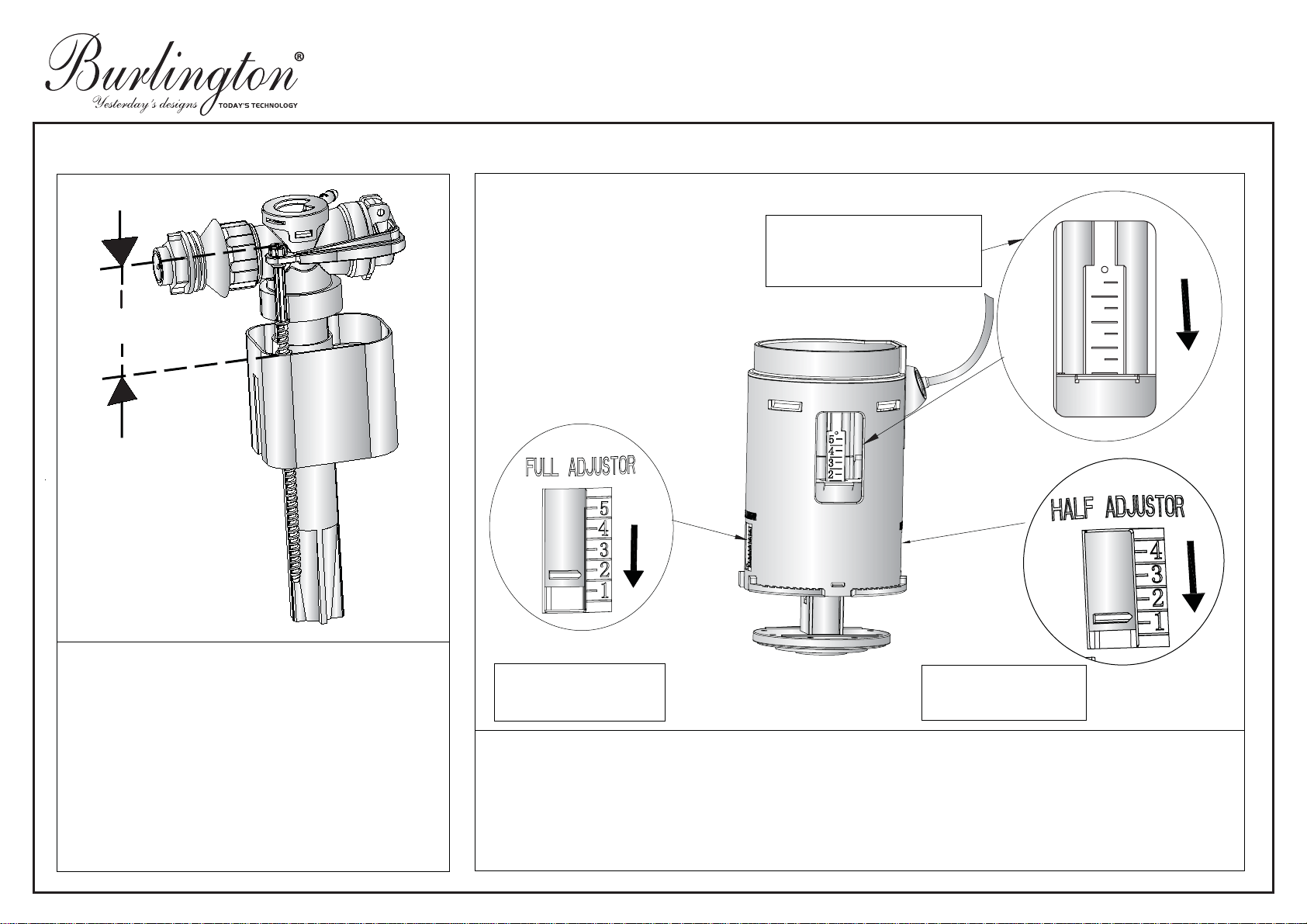
●Use the brass fixing nut (as part of the decorative cover) to fix in the cistern fittings.
Place the
decorative cover
and plastic fixing nut, plastic washer, cone shaped
washer (supplied as parts of the cistern fittings) over the top of the flush pipe (flush
pipe D) and insert into the threaded siphon stem (supplied as part of the
cistern fittings). Once the flush pipe is secured by the plastic fixing nut, screw the
decorative cover
up to the brass fixing nut.
●Insert the lower end of the flush pipe (flush pipe A) into the pan via the flush cone
(supplied as part of the cistern fittings).
●Locate the two buffer clips so as to secure the flush pipe to wall by fixing the wall
bracket upto wall. The buffer clip A will also prevent collision between the seat and
flush pipe.
●Put in the control bracket first,then join the pull handle to the lever arm. Fix the
control bracket to the wall 180mm above the pull handle.
●Mount the ornate brackets using the screws provided snugly under the cistern
(See hint 2).
Angled High Level Flush pipes (4 parts) T34 CHR
1. When installing your cistern, ensure that the rubber spacing washers are used to create
a small gap between the cistern back and the wall. There are two reasons for this; firstly it
will help to reduce the possibility of condensation when cold mains pressure is contained
within a humid environment and secondly, the gap will help prevent “thermal shock”. This is
when rapid temperature change occurs (usually overnight) and causes the wall to contract
or expand, thus cracking the sanitaryware. When fixing the cistern to the wall it is advisable
to insert the screw through a washer (not supplied) on the inside of the cistern. This will
prevent the screw damaging the sanitary ware when the screw “bites”.
* If required, for example if the wall is not level, please add additional spacers which are not
provided to ensure the cistern is level for fixing to the flush pipe.
2. The ornate brackets are purely decorative. They should not be used as support for the
cistern. Always ensure that the cistern is firmly and securely fixed to the wall via the fixing
holes at the rear of the tank.
HANDY HINT

A
2 - 3
Parts supplied:
1x
2x
decorative cover & brass fixing nut
flush pipe A
pull handle
ornate bracket
1x
buffer clip A
1x
control bracket
1x
screw
14x
rawl plug
14x
rubber spacing washer
4x
pin screw
1x
1x
flush pipe B
1x
flush pipe C
1x
flush pipe D
1x
1x
buffer clip B

A
3 - 3
Brass
Fixing Nut
Cone Shaped
Washer
Plastic Washer
Plastic
Fixing Nut
Decorative
Cover
Flush Pipe
Threaded
Siphon Stem
Ornate
Bracket
Pin Screw
4x
4x
2405mm
180mm
* The maximum overall height is 2405mm.
645mm
WALL
Note:
645mm measure is only
recommended installation
and the final decision
should be made by the
plumber on site depending
on the installation circumstance.
D
C
B
A
Buffer clip A
Control bracket
I
f necessary both
pipes (C, D)can be
cut at the end.
Buffer clip B
Inlet Hole
Flush Cone
Pan
Some adhesives
need to be added
at the joints.
Table of contents
Other Burlington Plumbing Product manuals
Popular Plumbing Product manuals by other brands

METHVEN
METHVEN 01-2053 installation guide

Kraus
Kraus KTCS-10 installation manual

Creda
Creda Aquawave White Installation and user guide

Luxart
Luxart EMBELLISH EB511TO Installation

Presenza
Presenza QL058 Installation guide and user's manual

Hans Grohe
Hans Grohe Sanibel 5001 A18 14736000 Instructions for use/assembly instructions

Vola
Vola RS1 FITTING INSTRUCTION

Tylo
Tylo Space Vision 200 Assembly instructions

ALDER TAPWARE
ALDER TAPWARE Vito Bertoni Series manual

PEERLESS
PEERLESS P188104LF-SD quick start guide

IKEA
IKEA RINNEN installation instructions

Hans Grohe
Hans Grohe Metris 110 Series Instructions for use/assembly instructions