BUSCH DUPLEX User manual

Operating instructions
DUPLEX / TRIPLEX
Vacuum systems
VRD 2072
VRD
3108
0870S03226/-0000_en / Translation of the original operating instructions / Subject to change without notice 10.02.2021
Dr.-Ing. K. Busch GmbH
Schauinslandstraße 1, 79689 Maulburg
Germany

2
/ 44 0870S03226_VRD 2072-3108_-
0000_IM_en

1 | Contents
0870S03226_VRD 2072-3108_-0000_IM_en
3/
44
1Contents
1.1 Table of contents
1Contents ......................................................................................... 3
1.1 Table of contents .............................................................................................................3
1.2 Register of tables .............................................................................................................5
1.3 Register of illustrations.....................................................................................................5
2Safety.............................................................................................. 6
2.1 Safety devices..................................................................................................................6
2.2 Emergency information....................................................................................................6
3Product description......................................................................... 7
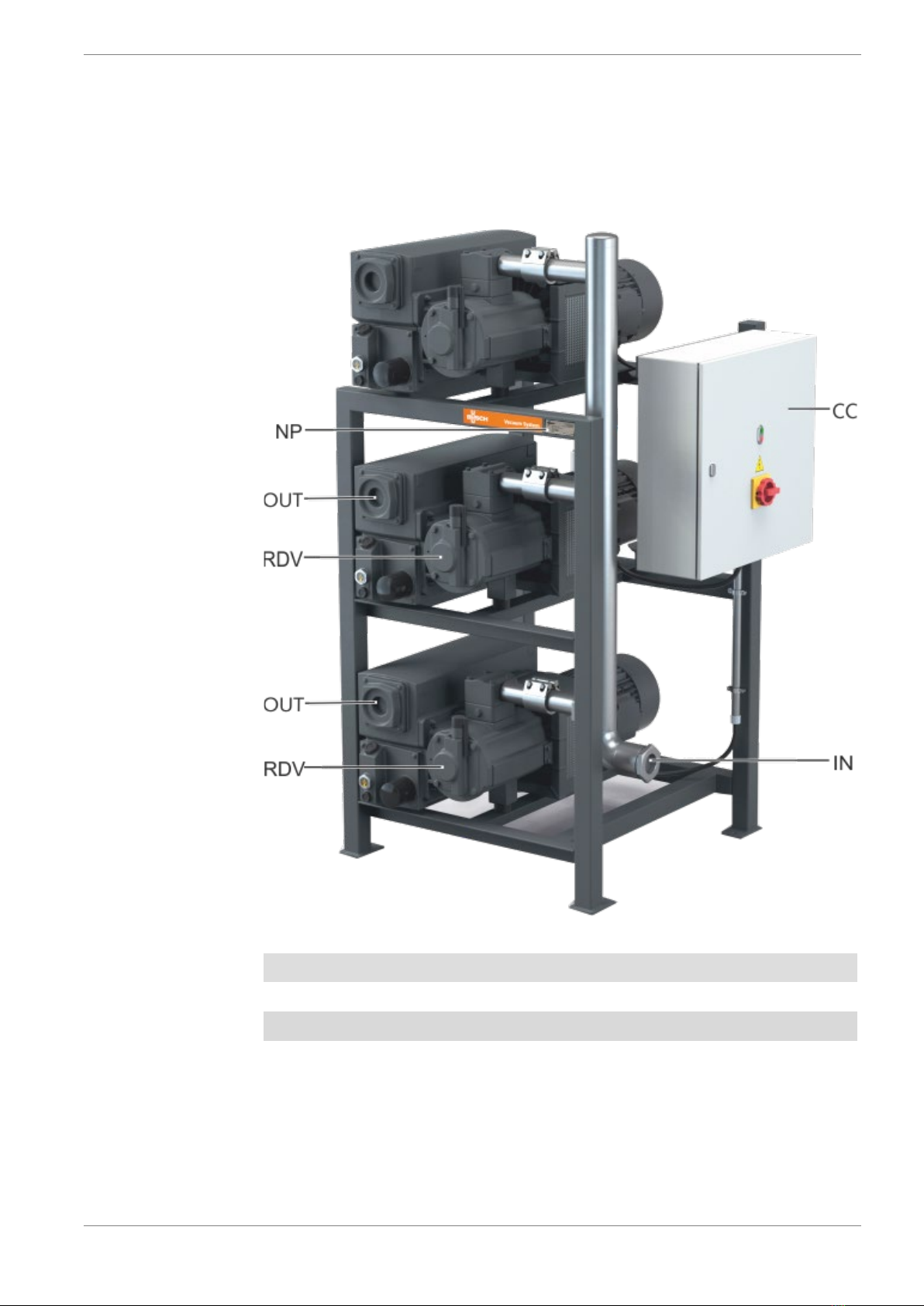
3.1 View vacuum system VRD (TRIPLEX) ..............................................................................7
3.2 View of the rotary vane vacuum pump RD......................................................................8
3.3 Setup ...............................................................................................................................8
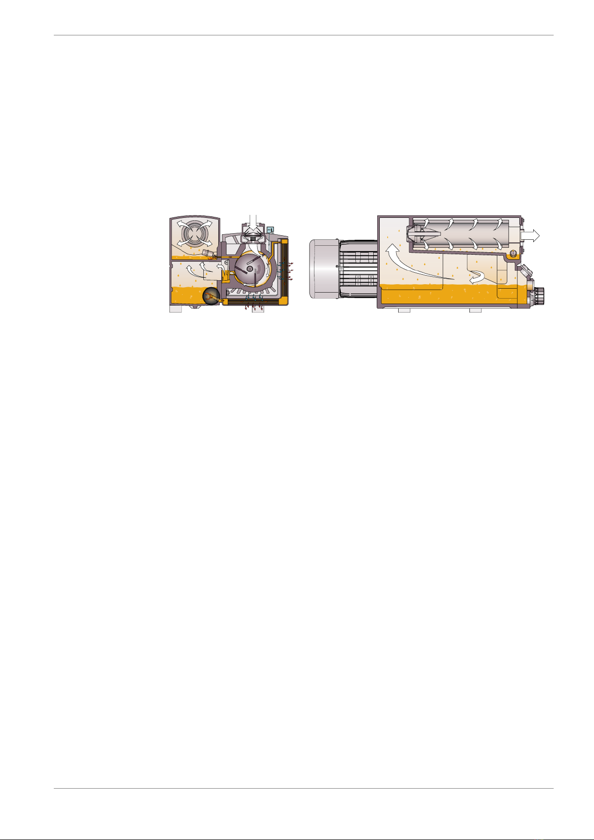
3.4 Function principle ............................................................................................................9
3.4.1 Vacuum system VRD .......................................................................................................9
3.4.2 Rotary vane vacuum pump R5 RD...................................................................................9
3.4.3 Gas ballast valve ..............................................................................................................9
3.5 Intended use....................................................................................................................9
4Transport ...................................................................................... 10
5Storage ......................................................................................... 13
6Installation.................................................................................... 14
6.1 Installation .....................................................................................................................14
6.2 Connection lines/pipes ..................................................................................................15
6.2.1 Gas inlet ........................................................................................................................15
6.2.2 Gas outlet ......................................................................................................................16
6.2.3 Cooling water connection (optional)..............................................................................17
6.3 Electrical connection ......................................................................................................18
6.3.1 Connection of the power supply....................................................................................18
7Start-up......................................................................................... 19
7.1 Indication and control elements .....................................................................................19
7.1.1 Topping up with oil........................................................................................................19
7.1.2 Display and control elements at the switching and control cabinet ................................20
7.1.3 Indicators and control elements on the vacuum system .................................................20
7.2 Operation ......................................................................................................................20
7.3 Conveying condensing vapors .......................................................................................21
8Maintenance................................................................................. 22
8.1 Maintenance plan..........................................................................................................22
8.2 Check oil level................................................................................................................23
8.3 Oil and oil filter change .................................................................................................23
8.4 Replacing the exhaust filters ..........................................................................................25
8.5 Cleaning the air heat exchanger ....................................................................................26

1 | Contents
4
/ 44 0870S03226_VRD 2072-3108_-
0000_IM_en
9Troubleshooting ........................................................................... 27
9.1 General faults ................................................................................................................27
9.2 Failure table and measures.............................................................................................28
10 Spare parts and accessories .......................................................... 30
10.1 Spare parts.....................................................................................................................30
10.2 Accessories ....................................................................................................................30
11 Repair ........................................................................................... 31
12 Decommissioning and disposal .................................................... 32
12.1 Stop operating vacuum system ......................................................................................32
12.2 Disassembly and disposal...............................................................................................32
13 Dimensions sheets........................................................................ 33
14 Connection values of the vacuum system VRD ............................ 38
14.1 Connection values .........................................................................................................38
14.2 Signal exchange.............................................................................................................38
15 Technical data............................................................................... 39
16 Oil ................................................................................................ 40
17 EU Declaration of conformity ....................................................... 41

1 | Contents
0870S03226_VRD 2072-3108_-0000_IM_en
5/
44
1.2 Register of tables
Tab. 1: Connections of the vacuum system DUPLEX VRD 2072 ..................................33
Tab. 2:Connections of the vacuum system DUPLEX VRD 2072
(water-cooled version) ........................................................................................34
Tab. 3: Connections of the vacuum system TRIPLEX VRD 3108..................................35
Tab. 4: Connections of the vacuum system DUPLEX VRD (connecting line)................36
Tab. 5: Connections of the vacuum system TRIPLEX VRD (connecting line) ...............37
Tab. 6: Connecting values of the vacuum systems VRD ...............................................38
1.3 Register of illustrations
Fig. 1 : View vacuum system VRD (TRIPLEX) .................................................................7
Fig. 2 : View of the rotary vane vacuum pump type R5 RD 0360 A .................................8
Fig. 3 : Operating principle of the rotary vane vacuum pump R5 RD ...............................9
Fig. 4 : Transport of the vacuum system with a lift truck ................................................11
Fig. 5 : Transport of the vacuum pump on the eye bolts ................................................12
Fig. 6 : Installation environment ......................................................................................14
Fig. 7 : Gas outlet............................................................................................................16
Fig. 8 : Cooling water connection ...................................................................................17
Fig. 9 : Topping up oil .....................................................................................................19
Fig. 10 : Switch and control cabinet .................................................................................20
Fig. 11 : Drain oil ..............................................................................................................23
Fig. 12 : Replacing the oil filter .........................................................................................24
Fig. 13 : Filling in oil..........................................................................................................24
Fig. 14 : Remove the exhaust filter...................................................................................25
Fig. 15 : Insert and tighten the new exhaust filter.............................................................25
Fig. 16 : Cleaning the air heat exchanger ........................................................................26
Fig. 17 : Vacuum pump with components relevant for troubleshooting ...........................27
Fig. 18 : Dimensions of the vacuum system DUPLEX VRD 2072 ...................................33
Fig. 19 : Dimensions of the vacuum system DUPLEX VRD 2072
(water-cooled version) ........................................................................................34
Fig. 20 : Dimensions of the vacuum system TRIPLEX VRD 3108...................................35
Fig. 21 : Dimensions vacuum system DUPLEX VRD (connecting line) ...........................36
Fig. 22 : Dimensions vacuum system TRIPLEX VRD (connecting line) ..........................37

2 | Safety
6
/ 44 0870S03226_VRD 2072-3108_-
0000_IM_en
2Safety
Before commissioning of the vacuum system, read these operating instructions with care.
Please contact your contact person from Busch if there are any questions.
Keep the operating instructions so that you can use them for reference at a later time if
necessary.
These operating instructions remain valid as long as the customer does not make any
changes to the product.
The vacuum system is intended for industrial use. It must only be operated by technically
trained specialists.
Always wear personal protective equipment in accordance with local regulations.
The vacuum system has been designed and produced according to state-of-the-art
methods. Nevertheless, a residual risk remains in operation. Potential dangers are high-
lighted in these operating instructions. Safety and warning notes are marked as follows,
with the words DANGER, WARNING, CAUTION, ATTENTION and NOTE:
DANGER
... Indicates a threatening hazard. Failure to observe safety instructions will result in death
or serious injury.
WARNING
... Indicates a potential hazard. Failure to observe safety instructions may result in death
or serious injury.
CAUTION
... Indicates a potential hazard. Failure to observe safety instructions may result in slight
injury.
ATTENTION!
... Indicates a potential hazard. Failure to observe safety instructions may result in prop-
erty damage.
NOTICE
... Indicates helpful advice and recommendations as well as information for efficient and
smooth operation.
2.1 Safety devices
The motor of the rotary vane vacuum pump is safeguarded by a motor protection switch.
If an overload occurs the vacuum system is shut down.
2.2 Emergency information
In an emergency case, the vacuum system can be switched off with the main switch of
the switch and control cabinet, which has the function of an emergency-stop switch.

3 | Product description
0870S03226_VRD 2072-3108_-0000_IM_en
7/
44
3Product description
3.1 View vacuum system VRD (TRIPLEX)
IN
Gas inlet
RDV
Rotary vane vacuum pump RD
OUT
Gas outlet
CC
Switch and control cabinet
NP
Name plate
Fig. 1 : View vacuum system VRD (TRIPLEX)

3 | Product description
8
/ 44 0870S03226_VRD 2072-3108_-
0000_IM_en
3.2 View of the rotary vane vacuum pump RD
AHE
Air-oil heat exchanger
DA
Rotation direction arrow motor
EB
Eye bolt
EF
Exhaust filter
GB
Gas ballast valve
IN
Suction connection
MTB
Motor terminal box
NP
Name plate
ODP
Oil drain plug
OF
Oil filter
OFP
Oil fill plug
OS
Oil separator
OSG
Oil sight glass
OUT
Gas outlet
Fig. 2 : View of the rotary vane vacuum pump type R5 RD 0360 A
3.3 Setup
The vacuum system DUPLEX / TRIPLEX VRD consists of two or three rotary vane vacu-
um pumps of the type R 5 RD 0360 A. These are arranged horizontally one above the
other in a base frame and connected on the suction side to a collecting line.
The strainer installed in the suction flange prevents the ingression of dirt particles into the
vacuum pump.
The gas ballast valve is used for the addition of a limited quantity of ambient air to the
process gas, to counteract the condensation of vapor in the vacuum pump.
The vacuum system is completely piped and the electrical components are wired on a
switch and control cabinet.

3 | Product description
0870S03226_VRD 2072-3108_-0000_IM_en
9/
44
3.4 Function principle
3.4.1 Vacuum system VRD
The switch and control cabinet is installed on the vacuum system. The rotary vane vacu-
um pumps are activated with soft-starters to avoid excessive mains loads. When
switched on, the first rotary vane vacuum pump starts immediately, the other rotary
vane vacuum pumps are switched on one after the other with a time offset of 10 s.
Gas delivery is effected by the one-stage rotary vane vacuum pumps. Pressure gas is ex-
hausted against the atmosphere.
3.4.2 Rotary vane vacuum pump R5 RD
Fig. 3 : Operating principle of the rotary vane vacuum pump R5 RD
The vacuum pump R5 RD works according to the rotary vane principle.
The oil seals the spaces, lubricates the sliders and discharges the compression heat. The
oil filter cleans the circulating oil.
Then the exhaust filters separate the oil from the discharged gas.
3.4.3 Gas ballast valve
The vacuum pumps are equipped with a gas ballast valve. The gas ballast valve is used
for the addition of a limited quantity of ambient air to the process gas, to counteract the
condensation of vapor in the vacuum pump. The gas ballast valve reduces the final pres-
sure of the vacuum pump, see “Technical data” in chap. 15.
3.5 Intended use
The vacuum system was designed for conveying air and other dry, non-aggressive, non-
toxic and non-explosive gases.
Conveying any other media leads to increased thermal and/or mechanical stress of the
vacuum system and is only permitted in coordination with Busch.
The vacuum system is designed for operation in a non-hazardous area. The vacuum sys-
tem can be operated continuously at final pressure and is suitable for continuous opera-
tion at up to 100 mbar. The permitted ambiance conditions can be found in the technical
data (chap. 15).
The vacuum system is designed for indoor use; for outdoor installation, contact Busch to
make special arrangements if necessary.

4 | Transport
10
/ 44 0870S03226_VRD 2072-3108_-
0000_IM_en
4Transport
WARNING
Danger of severe injury!
Suspended load.
•Never walk, stand or work below suspended loads.
WARNING
Hazard from vacuum system falling or tipping over!
The weight of the vacuum system can kill a person or cause severe crushing.
•The vacuum system can be moved with a forklift or lift truck.
Observe the center of gravity and the lifting points; these are indicated in the scale
drawings, see chap. 13.
ATTENTION!
Damage to the vacuum system!
If the vacuum system is already filled with oil.
•Drain the oil before transport if transport in horizontal orientation is not possible.
The vacuum system is packed in a wooden crate. It protects the system from damage
during transport.
The vacuum system is packed in a wooden structure and can be moved using a forklift.
•Unpack the vacuum system as near to the installation site as possible.
•Check scope of delivery for completeness.
•Check the vacuum system for transport damage.
•Dispose of packing material as required by current regulations.

4 | Transport
0870S03226_VRD 2072-3108_-0000_IM_en
11 /
44
WARNING
Danger of severe injury!
Lift the vacuum system by devices of the individual components.
•Do not lift the vacuum system by devices of the individual components,
e.g. the vacuum pump, motor, etc.
•Only lift the vacuum system as presented.
Fig. 4 : Transport of the vacuum system with a lift truck

4 | Transport
12
/ 44 0870S03226_VRD 2072-3108_-
0000_IM_en
The vacuum pump can be lifted by the eye bolts.
WARNING
Danger of severe injury!
Suspended load.
•Never walk, stand and work below suspended loads!
•The eye bolts (EB) must be in perfect condition and completely screwed into the ma-
chine and hand-tightened!
ATTENTION!
Damage to the vacuum system!
If the vacuum pump is already filled with oil.
Tilting a vacuum pump that is already filled with oil can cause large amounts of oil to
enter the cylinder. If the vacuum pump is started while there are excessive amounts of
oil in the cylinder, this will damage the sliders, resulting in a total damage of the vacu-
um pump.
•Drain the oil before transport if transport in horizontal orientation is not possible.
Fig. 5 : Transport of the vacuum pump on the eye bolts
Weight of the machine:
see technical data or see name plate (NP)

5 | Storage
0870S03226_VRD 2072-3108_-0000_IM_en
13 /
44
5Storage
ATTENTION!
Danger of damage to the vacuum pump drive!
Long storage periods may cause capacitors in the drive to be weakened by electro-
chemical condensation. In the most detrimental case, this may cause short-circuit and
thereby destruction of the drive.
•The vacuum pump should therefore be connected to the power supply for 30 minutes
every 18 months.
Proceed as follows for storage:
•Close all openings with the protective caps included in the scope of delivery (penetra-
tion of dirt and water is prevented)
If storage for more than 3 months is intended:
•Secure loose cables
•Drain all process and operating media
•Clean and dry the vacuum system (Prior to storing make absolutely sure that all parts
are clean, drained and dry)
•Where necessary use oil for conservation
•Wrap the vacuum system in corrosion-inhibiting film.
•Store the vacuum system in a protected, dry and dust-free room at a temperature be-
tween 0 and 40 °C.

6 | Installation
14
/ 44 0870S03226_VRD 2072-3108_-
0000_IM_en
6Installation
6.1 Installation
Fig. 6 : Installation environment
•Ensure that the vacuum system is set up horizontally (deviation 1° max.) and anchor it
in the ground with four bolts if necessary.
•Technical data must be complied with.
•The ambiance conditions must meet the protection class of the vacuum pump.
•The installation site must be vented so that sufficient cooling of the vacuum system is
ensured.
•Ensure that the ventilation openings (inlets and outlets) are not covered and that the
cooling air can flow unhindered.
•Sufficient space for maintenance work must be ensured.
•Visibility of the oil sight glass (OSG, Fig. 2) must be ensured at all times.
•Check the oil level and top up oil if necessary (for more information, see topping up
with oil (chap. 7.1.1).
•Ensure that all covers, safety devices, etc. are installed.

6 | Installation
0870S03226_VRD 2072-3108_-0000_IM_en
15 /
44
6.2 Connection lines/pipes
ATTENTION!
Danger of damage to the vacuum system from foreign bodies in the pipes.
•Remove all foreign matter (welding beads, filings, etc.) from the pipelines! This may
be done by flushing or blowing through pipelines.
•The client must ensure that the pipework at the inlet is clean.
•If the sucked gas contains dust or other solids, install a filter (separation efficiency up
to 5 micrometers) upstream of the vacuum pump inlet to protect the vacuum system.
ATTENTION!
Vacuum system can be damaged by tensile or compressive stresses on pipeline connec-
tions!
•If stresses could occur, use compensators to connect pipelines.
ATTENTION!
Condensate damages vacuum pumps!
•Lay the piping on the intake and pressure sides at an angle to prevent accumulated
condensation from entering the vacuum pump.
The line cross-section of the connection lines must have at least the same cross-section
as the connections of the vacuum system across the entire length.
In case of very long connection lines, it is recommended to use lines with larger cross-
sections to avoid loss of efficiency. Please contact your contact person from Busch.
6.2.1 Gas inlet
WARNING
Danger of severe injury!
Open gas inlet!
•Never insert your hand or fingers into the gas inlet!
Connect the suction-side tubing to the gas inlet of the vacuum system (IN, Fig. 1).
NOTICE
Before initial start-up check the pipelines to the vacuum system for leaks. Rectify any
leaks.
Dimensions see scale drawings in the appendix.

6 | Installation
16
/ 44 0870S03226_VRD 2072-3108_-
0000_IM_en
6.2.2 Gas outlet
CAUTION
Health risk!
The discharged gas contains small amounts of oil.
Ensure sufficient ventilation in the installation room when the air is routed into rooms
where there are people.
•Connect the gas outlet line to the gas outlet of the vacuum pump if necessary. Dimen-
sions, see scale drawing in the appendix (connection size: flange with thread G 2").
•Ensure that the discharged gas can flow off unhindered. Never close the gas outlet line,
do not throttle it and do not use it as a compressed air source.
If the air taken in is not discharged to the environment in the direct proximity of the vac-
uum system, observe the following:
•Place the gas outlet line dropping towards the vacuum system or install a liquid separa-
tor or a siphon with a drain valve so that no liquid can flow back into the vacuum sys-
tem.
Fig. 7 : Gas outlet

6 | Installation
0870S03226_VRD 2072-3108_-0000_IM_en
17 /
44
6.2.3 Cooling water connection (optional)
•Connect the cooling water line to the cooling water inlet of the vacuum pump (CWI,
fig. 8).
•Connect the cooling water line to the cooling water outlet of the vacuum pump
(CWO, fig. 8).
Connection size: 19 mm hose (CWI/CWO).
CWI
Cooling water supply
WHE
Oil/water heat exchanger
CWO
Cooling water drain
Fig. 8 : Cooling water connection
Regarding the cooling water, the following prerequisites must be met:
Supply capacity
l/min.
2.5
Water pressure bar 2 … 6
Supply temperature
°C
+5 … +35
Required differential pressure between the inlet and return
bar
≥ 1
We recommend the following water qualities to keep the maintenance effort limited and
extend the service life of the product:
Hardness
mg/l (ppm)
<90
Properties
pure and clear
pH value 7-8
Particle size
µm
<200
Chlorine
mg/l
<100
Electrical conductivity
µS/cm
≤100
Free chlorine
mg/l
<0.3
Materials in contact with cooling water
Rust-free steel, copper and cast iron
NOTICE
Conversion of the unit for water hardness.
1 mg/l (ppm) = 0.056 °dh (German degree) = 0.07 °e (English degree)
= 0.1 °fH (French degree).

6 | Installation
18
/ 44 0870S03226_VRD 2072-3108_-
0000_IM_en
6.3 Electrical connection
DANGER
Danger from electric shock!
Electric shock will cause death or serious injury.
•All live lines must be powered down before the electrical installation!
•Before any electrical work, ensure that the vacuum pump is disconnected from the
power supply and secured against accidental activation.
•Electrical installation work must only be performed by trained specialists.
ATTENTION!
Incorrect rotation of drive motors can seriously damage the vacuum system!
Switch vacuum pumps briefly on and off again to check the rotational direction of the
motor. The rotational direction is marked by a direction of rotation arrow on the motor.
If the direction is wrong, reverse two connection phase poles.
6.3.1 Connection of the power supply
ATTENTION!
Danger of damage to the vacuum system.
Wrong connection.
Wire the vacuum system according to the circuit diagram in the switch and control cabi-
net.
Procedure:
•Ensure that the power supply for the vacuum system corresponds to the specifications
in the circuit diagram.
•Ensure that the vacuum system is not impaired by electrical or electromagnetic impuls-
es of the power supply. Contact Busch if necessary.
•Connect the switch and control cabinet to the power supply (for connection values, see
chap. 14).
ATTENTION!
Danger of damage to the motor
Wrong rotating direction.
•Operation in the wrong rotating direction may damage the vacuum system after a
very brief time. Ensure that the rotating direction is correct before commissioning.
•Use the glued-on/cast-in arrow to determine the intended rotating direction.
•Switch on the vacuum pump for a fraction of a second.
•Observe the fan wheel and determine the rotating direction just before standstill.
To change the rotating direction:
•Swap any two phases of the power supply.

7 | Start-up
0870S03226_VRD 2072-3108_-0000_IM_en
19 /
44
7Start-up
7.1 Indication and control elements
DANGER
Danger from electric shock!
Electric shock will cause death or serious injury.
•Before commissioning, ensure that all electrical lines are covered and that the terminal
box is closed!
CAUTION
Burn hazard!
The surface of the vacuum pump may reach operating temperatures in excess of 70 °C
in operation.
Do not touch the vacuum pump during and directly after operation.
ATTENTION!
Insufficient familiarity with the indicators and operating controls may result in damage
to the vacuum system.
Wrong operation.
•Operating staff must be familiar with the indicating and operating elements.
ATTENTION!
Operation of the vacuum pump without oil will cause severe damage to it quickly.
•The vacuum system is not filled with oil at delivery. Before start-up, the vacuum
pumps have to be filled with oil and the oil level must be checked.
7.1.1 Topping up with oil
For information on the oil type and oil volume, see the technical data (chap. 15) and oil
(chap. 16).
Fig. 9 : Topping up oil
Check oil level
MAX
MIN
1 x o-ring, part no.:
see “Maintenance kit” (spare parts)

7 | Start-up
20
/ 44 0870S03226_VRD 2072-3108_-
0000_IM_en
7.1.2 Display and control elements at the switching and control
cabinet
Fig. 10 : Switch and control cabinet
1. Double pushbutton (I / 0)
Double pushbutton for switching on and off the vacuum system
2. Main switch
Switch on and off the entire vacuum system
7.1.3 Indicators and control elements on the vacuum system
The indicating devices are as follows:
•Oil sight glass (OSG, Fig. 2) at the vacuum pump
7.2 Operation
CAUTION
Burn hazard!
The surface of the vacuum pump may reach operating temperatures in excess of 70 °C
in operation.
Do not touch the vacuum pump during and directly after operation.
CAUTION
Danger of hearing damage.
Noise development of the running vacuum pump.
Use hearing protection near the vacuum pump.
•Ensure that the installation conditions (chap. 6.1) are met.
•The permitted maximum number of starts (12) per hour must not be exceeded.
When the vacuum pump is operated under normal operating conditions, proceed as fol-
lows:
•Measure the motor current and record it for reference purposes for future maintenance
work and for troubleshooting.
•After a few minutes of vacuum operation, check the oil level and top up oil if neces-
sary.
This manual suits for next models
3
Table of contents
Other BUSCH Vacuum Cleaner manuals