BUSCH SIMPLEX VO 0040 B User manual

Operating instructions
SIMPLEX
Vacuum systems
VO 0040 –0080 B
0870S03254/-0000_en / Translation of the original operating instructions / Subject to change without notice 08.03.2021
Dr.-Ing. K. Busch GmbH
Schauinslandstraße 1, 79689 Maulburg
Germany

2/ 52
0870S03254_VO 0040-0080_B_-0000_IM_en

1 | Contents
0870S03254_VO 0040-0080_B_-0000_IM_en
3/ 52
1Contents
1.1 17BTable of contents
1Contents............................................................................................. 3
1.1 Table of contents .........................................................................................................................3
1.2 Register of tables .........................................................................................................................5
1.3 Register of illustrations................................................................................................................5
2Safety................................................................................................. 6
2.1 Safety devices ..............................................................................................................................6
2.2 Emergency information ...............................................................................................................6
3Product description ............................................................................ 7
3.1 View vacuum system VO .............................................................................................................7
3.2 View of the claw-type vacuum pump MV ...................................................................................8
3.3 Setup............................................................................................................................................8
3.4 Function principle ........................................................................................................................9
3.4.1 Vacuum system VO......................................................................................................................9
3.4.2 Claw-type vacuum pump MV ......................................................................................................9
3.5 Intended use................................................................................................................................9
4Transport...........................................................................................10
5Storage..............................................................................................13
6Installation ........................................................................................14
6.1 Installation .................................................................................................................................14
6.2 Connection lines/pipes ..............................................................................................................15
6.2.1 Gas inlet.....................................................................................................................................15
6.2.2 Gas outlet ..................................................................................................................................16
6.3 Electrical connection..................................................................................................................17
6.3.1 Connection of the power supply ...............................................................................................17
7Start-up.............................................................................................19
7.1 Indication and control elements................................................................................................19
7.1.1 Topping up with oil ....................................................................................................................19
7.1.2 Indicators and control elements on the motor protection switch ............................................20
7.1.3 Indicators and control elements on the vacuum system ..........................................................20
7.1.4 LED display at the vacuum pump...............................................................................................20
7.1.5 DIP switches...............................................................................................................................21
7.1.6 Manual operating unit (option) .................................................................................................22
7.1.7 Measuring and control facilities and settings............................................................................23
7.1.8 Parameter settings ....................................................................................................................24
7.2 Operation...................................................................................................................................25
7.3 Pressure control.........................................................................................................................25

1 | Contents
4/ 52
0870S03254_VO 0040-0080_B_-0000_IM_en
8Maintenance .....................................................................................26
8.1 Maintenance plan ..................................................................................................................... 26
8.2 Check oil level............................................................................................................................ 27
8.3 Clean vacuum system from dust and dirt ................................................................................. 27
8.4 Oil change.................................................................................................................................. 28
8.5 Changing of the air filter element ............................................................................................. 29
8.6 Check and clean suction strainer............................................................................................... 29
9Troubleshooting ................................................................................30
9.1 Failure table and measures ....................................................................................................... 30
9.2 Fault messages at the manual operating unit........................................................................... 31
9.3 Resetting error .......................................................................................................................... 32
10 Spare parts and accessories ...............................................................33
10.1 Spare parts ................................................................................................................................ 33
10.2 Accessories................................................................................................................................ 33
10.2.1 Parametrization Kit.................................................................................................................... 33
10.2.2 Manual operating unit............................................................................................................... 33
10.2.3 Field bus option card................................................................................................................. 34
11 Repair................................................................................................35
12 Decommissioning and disposal ..........................................................36
12.1 Stop operating vacuum system................................................................................................. 36
12.2 Disassembly and disposal.......................................................................................................... 36
13 Dimensions sheets.............................................................................37
14 Connecting values of the vacuum system VO .....................................43
14.1 Connection values ..................................................................................................................... 43
14.2 Circuit diagram vacuum systems VO......................................................................................... 44
14.3 Circuit diagram of the claw vacuum pump MV 0040 D / MV 0060 D / MV 0080 D, 3 phase.... 45
14.4 Electrical data of the terminals of the control unit ................................................................... 46
15 Technical data ...................................................................................47
16 Gear oil..............................................................................................48
17 EU Declaration of conformity.............................................................49

1 | Contents
0870S03254_VO 0040-0080_B_-0000_IM_en
5/ 52
1.2 18BRegister of tables
Tab. 1: Switching values.................................................................................................23
Tab. 2: Parameter settings (factory settings)..................................................................24
Tab. 3: Connections vacuum system VO 0040 B AAA G3XX........................................37
Tab. 4: Connections vacuum system VO 0040 B AAA G3AX (mobile)..........................38
Tab. 5: Connections vacuum system VO 0060 B AAA H3XX........................................39
Tab. 6: Connections vacuum system VO 0060 B AAA H3AX (mobile)..........................40
Tab. 7: Connections vacuum system VO 0080 B AAA I3XX..........................................41
Tab. 8: Connections vacuum system VO 0080 B AAA I3AX (mobile)............................42
Tab. 9: Connecting values of the vacuum systems VO..................................................43
Tab. 10:Electrical data of the terminals of the control unit ..............................................46
Tab. 11:Technical data ....................................................................................................47
Tab. 12:Gear oil...............................................................................................................48
1.3 19BRegister of illustrations
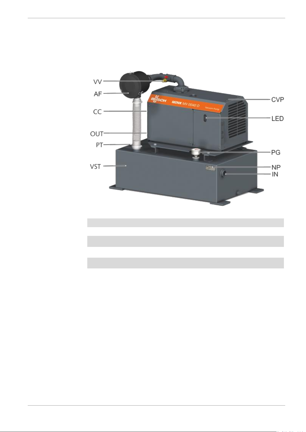
Fig. 1: View vacuum system VO......................................................................................7
Fig. 2: View claw vacuum pump Mink type MV...............................................................8
Fig. 3: Operating principle of the claw vacuum pump MV...............................................9
Fig. 4: Transport of the vacuum system........................................................................11
Fig. 5: Transport of the vacuum pump on the eye bolts................................................12
Fig. 6: Installation environment......................................................................................14
Fig. 7: Gas outlet ...........................................................................................................16
Fig. 8: Topping up oil.....................................................................................................19
Fig. 9: Motor protection switch.......................................................................................20
Fig. 10:LED displays at the vacuum pump.....................................................................20
Fig. 11:DIP switch on the vacuum pump........................................................................21
Fig. 12:Display of the manual operating unit..................................................................22
Fig. 13:Display overview.................................................................................................22
Fig. 14:Connection of the operating unit to vacuum pump.............................................23
Fig. 15:Clean vacuum pump...........................................................................................27
Fig. 16:Drain oil ..............................................................................................................28
Fig. 17:Filling in oil..........................................................................................................28
Fig. 18:Cleaning of the air filter element.........................................................................29
Fig. 19:Installing the intake screen.................................................................................29
Fig. 20:Dimensions vacuum system VO 0040 B AAA G3XX.........................................37
Fig. 21:Dimensions vacuum system VO 0040 B AAA G3AX (mobile)...........................38
Fig. 22:Dimensions vacuum system VO 0060 B AAA H3XX .........................................39
Fig. 23:Dimensions vacuum system VO 0060 B AAA H3AX (mobile)...........................40
Fig. 24:Dimensions vacuum system VO 0080 B AAA I3XX...........................................41
Fig. 25:Dimensions vacuum system VO 0080 B AAA I3XX(mobile)..............................42
Fig. 26:Circuit diagram vacuum systems VO.................................................................44
Fig. 27:Circuit diagram MV 0040 D / MV 0060 D / MV 0080 D, 3 phase.......................45

2 | Safety
6/ 52
0870S03254_VO 0040-0080_B_-0000_IM_en
2Safety
Before commissioning of the vacuum system, read these operating instructions with care.
Please contact your contact person from Busch if there are any questions.
Keep the operating instructions so that you can use them for reference at a later time if nec-
essary.
These operating instructions remain valid as long as the customer does not make any changes
to the product.
The vacuum system is intended for industrial use. It must only be operated by technically
trained specialists.
Always wear personal protective equipment in accordance with local regulations.
The vacuum system has been designed and produced according to state-of-the-art methods.
Nevertheless, a residual risk remains in operation. Potential dangers are highlighted in these
operating instructions. Safety and warning notes are marked as follows, with the words DAN-
GER, WARNING, CAUTION, ATTENTION and NOTE:
DANGER
... Indicates a threatening hazard. Failure to observe safety instructions will result in death or
serious injury.
WARNING
... Indicates a potential hazard. Failure to observe safety instructions may result in death or se-
rious injury.
CAUTION
... Indicates a potential hazard. Failure to observe safety instructions may result in slight inju-
ry.
ATTENTION!
... Indicates a potential hazard. Failure to observe safety instructions may result in property
damage.
NOTICE
... Indicates helpful advice and recommendations as well as information for efficient and
smooth operation.
2.1 20BSafety devices
The motor of the rotary vane vacuum pump is safeguarded by a motor protection switch. If an
overload occurs the vacuum system is shut down.
2.2 21BEmergency information
In an emergency, the vacuum system can be switched off with the main switch of the motor
protection switch, which has the function of an emergency-stop switch.

3 | Product description
0870S03254_VO 0040-0080_B_-0000_IM_en
7/ 52
3Product description
3.1 22BView vacuum system VO
IN
Gas inlet
CC
Motor protection switch
OUT
Gas outlet
AF
Air filter
CVP
Claw-type vacuum pump MV
VV
Venting valve
NP
Name plate
PT
Pressure transmitter
PG
Vacuum gauge
VST
Vacuum vessel
LED
LED frequency converter
Fig. 1: View vacuum system VO

3 | Product description
8/ 52
0870S03254_VO 0040-0080_B_-0000_IM_en
3.2 23BView of the claw-type vacuum pump MV
IN
Suction connection
CAO
Cooling air outlet
OUT
Gas outlet
VFD
Frequency controlled drive
OFP
Oil filler plug (oil dipstick)
CD
Condensate drain
(aqua version)
ODP
Oil drain plug
(under the cover)
MC
Connection supply voltage
CAI
Cooling air inlet
EB
Eye bolt
NP
Name plate
Fig. 2: View claw vacuum pump Mink type MV
3.3 24BSetup
The vacuum system SIMPLEX VO consists of a single-stage claw vacuum pump type MV with
integrated frequency converter for the drive. The vacuum pump is mounted on a vacuum ves-
sel.
The intake-side air filter and the strainer installed in the suction flange prevent the ingression
of dirt particles in the vacuum pump.
A pressure transmitter for pressure control is installed at the vacuum tank. The pressure in
the vacuum tank can be read using a vacuum meter.
Inlet and delivery side of vacuum system are completely piped. The motor is wired to a motor
protection switch.
The vacuum system is also available as a movable version with four rollers and a sliding brack-
et.

3 | Product description
0870S03254_VO 0040-0080_B_-0000_IM_en
9/ 52
3.4 25BFunction principle
3.4.1 50BVacuum system VO
The single-stage claw vacuum pump evacuates a vacuum tank (VST, fig. 1), which serves as a
vacuum reservoir. The compressed gas of the vacuum pump is ejected against the atmos-
phere.
An air filter is installed between the vacuum pump and the vacuum vessel. The delivered gas
passes from the vacuum vessel to the air filter through to the vacuum pump. The air filter is
used to separate dust and other solid foreign substances from the extraction medium.
After switching on the main switch, the vacuum pump switches on. Via the pressure transmit-
ter installed in the vacuum vessel, the rotation speed of the motor is controlled by the fre-
quency converter depending on the pressure. If no vacuum is needed for some period (ad-
justable), the vacuum pump will switch itself off. When the set target pressure is exceeded,
the vacuum pump will switch on again automatically.
3.4.2 51BClaw-type vacuum pump MV
Fig. 3: Operating principle of the claw vacuum pump MV
The claw vacuum pump MV operates according to the claw principle.
3.5 26BIntended use
The vacuum system was designed for conveying air and other dry, non-aggressive, non-toxic
and non-explosive gases.
Conveying any other media leads to increased thermal and/or mechanical stress of the vacu-
um system and is only permitted in coordination with Busch.
The vacuum system is designed for operation in a non-hazardous area. The vacuum system
can be operated continuously at final pressure and is suitable for continuous operation at up
to 40 mbar. The permitted ambiance conditions can be found in the technical data (chap. 15).
The vacuum system is designed for indoor use; for outdoor installation, contact Busch to
make special arrangements if necessary.

4 | Transport
10 / 52
0870S03254_VO 0040-0080_B_-0000_IM_en
4Transport
WARNING
Danger of severe injury!
Suspended load.
•Never walk, stand or work below suspended loads.
WARNING
Hazard from vacuum system falling or tipping over!
The weight of the vacuum system can kill a person or cause severe crushing.
•Use a pallet appropriate to the weight and size of the system on which it can be moved by
a forklift truck. Or lift the vacuum system using slings and suitable lifting gears with a fork-
lift or lift truck to move it or remove the pallet.
•Take care to avoid strain on the pipe work and vacuum pumps while placing the slings.
•Observe the center of gravity and the lifting points; these are indicated in the scale draw-
ings, see chap. 13.
ATTENTION!
Damage to the vacuum system!
The vacuum system is already filled with gear oil at delivery.
•Drain the oil before transport if transport in horizontal orientation is not possible.
The vacuum system is packed in a wooden crate. It protects the system from damage during
transport.
The vacuum system is packed in a wooden structure and can be moved using a forklift.
•Unpack the vacuum system as near to the installation site as possible.
•Check scope of delivery for completeness.
•Check the vacuum system for transport damage.
•Dispose of packing material as required by current regulations.

4 | Transport
0870S03254_VO 0040-0080_B_-0000_IM_en
11 / 52
WARNING
Danger of severe injury!
Lift the vacuum system by devices of the individual components.
•Do not lift the vacuum system by devices of the individual components,
e.g. the vacuum pump, motor, etc.
•Only lift the vacuum system as presented.
Fig. 4: Transport of the vacuum system
Screw four M10 eye bolts (not included in the scope of delivery) into the holes on the feet of
the vacuum vessel (see fig. 4). Pass slings through the openings of the eye bolts and thus lift
the vacuum system with a crane or a forklift.

4 | Transport
12 / 52
0870S03254_VO 0040-0080_B_-0000_IM_en
The vacuum pump can be lifted by the eye bolts.
WARNING
Danger of severe injury!
Suspended load.
•Never walk, stand and work below suspended loads!
•The eye bolts (EB) must be in perfect condition and completely screwed into the machine
and hand-tightened!
•Do not lift the vacuum pump on an eye bolt of the motor. Lift the vacuum pump only as
shown.
Fig. 5: Transport of the vacuum pump on the eye bolts
Check the vacuum pump for transport damage.
If the vacuum pump is fixed on a base plate, remove it.
Machine weight:
See technical data or nameplate (NP)

5 | Storage
0870S03254_VO 0040-0080_B_-0000_IM_en
13 / 52
5Storage
ATTENTION!
Danger of damage to the vacuum pump drive!
Long storage periods may cause capacitors in the drive to be weakened by electro-chemical
condensation. In the most detrimental case, this may cause short-circuit and thereby destruc-
tion of the drive.
•The vacuum pump should therefore be connected to the power supply for 30 minutes eve-
ry 18 months.
Proceed as follows for storage:
•Close all openings with the protective caps included in the scope of delivery (penetration of
dirt and water is prevented)
If storage for more than 3 months is intended:
•Secure loose cables
•Drain all process and operating media
•Clean and dry the vacuum system (Prior to storing make absolutely sure that all parts are
clean, drained and dry)
•Where necessary use oil for conservation
•Wrap the vacuum system in corrosion-inhibiting film.
•Store the vacuum system in a protected, dry and dust-free room at a temperature between
0 and 40 °C.

6 | Installation
14 / 52
0870S03254_VO 0040-0080_B_-0000_IM_en
6Installation
6.1 27BInstallation
Fig. 6: Installation environment
•Ensure that the vacuum system is set up horizontally (deviation 1° max.) and anchor it in the
ground with four bolts if necessary.
•Technical data must be complied with.
•The ambiance conditions must meet the protection class of the vacuum pump.
•The installation site must be vented so that sufficient cooling of the vacuum system is en-
sured.
•Ensure that the ventilation openings (inlets and outlets) are not covered and that the cool-
ing air can flow unhindered.
•Sufficient space for maintenance work must be ensured.
•The visibility of the display elements (PG, fig. 1) must be ensured.
•Ensure that all covers, safety devices, etc. are installed.

6 | Installation
0870S03254_VO 0040-0080_B_-0000_IM_en
15 / 52
6.2 28BConnection lines/pipes
ATTENTION!
Danger of damage to the vacuum system from foreign bodies in the pipes.
•Remove all foreign matter (welding beads, filings, etc.) from the pipelines! This may be
done by flushing or blowing through pipelines.
The client must ensure that the pipework at the inlet is clean.
ATTENTION!
Vacuum system can be damaged by tensile or compressive stresses on pipeline connec-
tions!
•If stresses could occur, use compensators to connect pipelines.
ATTENTION!
Condensate damages vacuum pumps!
•Lay the piping on the intake and pressure sides at an angle to prevent accumulated con-
densation from entering the vacuum pump.
The line cross-section of the connection lines must have at least the same cross-section as the
connections of the vacuum system across the entire length.
In case of very long connection lines, it is recommended to use lines with larger cross-sections
to avoid loss of efficiency. Please contact your contact person from Busch.
6.2.1 52BGas inlet
WARNING
Danger of severe injury!
Open gas inlet!
•Never insert your hand or fingers into the gas inlet!
Connect the suction side pipeline to the gas inlet of the vacuum system (IN, fig. 1).
NOTICE
Before initial start-up check the pipelines to the vacuum system for leaks. Rectify any leaks.
Dimensions see scale drawings in the appendix.

6 | Installation
16 / 52
0870S03254_VO 0040-0080_B_-0000_IM_en
6.2.2 53BGas outlet
•Connect the gas outlet line to the gas outlet openings of the vacuum pump if required. Di-
mensions, see scale drawing in the appendix; connection size of thread: G 3/4“.
•Ensure that the discharged gas can flow off unhindered. Never close the gas outlet line, do
not throttle it and do not use it as a compressed air source.
If the air taken in is not discharged to the environment in the direct proximity of the vacuum
system, observe the following:
•Place the gas outlet line dropping towards the vacuum system or install a liquid separator or
a siphon with a drain valve so that no liquid can flow back into the vacuum system.
Fig. 7: Gas outlet

6 | Installation
0870S03254_VO 0040-0080_B_-0000_IM_en
17 / 52
6.3 29BElectrical connection
DANGER
Danger from electric shock!
Electric shock will cause death or serious injury.
•All live lines must be powered down before the electrical installation!
•Before any electrical work, ensure that the vacuum pump is disconnected from the power
supply and secured against accidental activation. Wait for another 60 seconds after the
LED displays switch off.
•Electrical installation work must only be performed by trained specialists.
ATTENTION!
Incorrect rotation of drive motors can seriously damage the vacuum system!
Switch vacuum pumps briefly on and off again to check the rotational direction of the motor.
The rotational direction is marked by a direction of rotation arrow on the motor.
If the direction is wrong, reverse two connection phase poles.
ATTENTION!
Over voltage damages the vacuum system.
During a high-voltage test, the frequency inverter must be disconnected due to danger of de-
stroying the power semi-conductors. The frequency inverter has already been subjected to a
high-voltage test with special test process in the final inspection.
6.3.1 54BConnection of the power supply
CAUTION
Danger due to accidental starting of the vacuum pump!
The vacuum pump starts up when the main switch is actuated.
Make sure that starting the vacuum pump does not lead to a dangerous situation.
ATTENTION!
Danger of damage to the vacuum system.
Wrong connection.
•Wire the vacuum system according to the wiring diagram chap. 14.2.
Procedure:
•Ensure that the power supply for the vacuum system corresponds to the specifications in
the circuit diagram.
•Ensure that the EMC class of the vacuum pump meets the requirements of your mains grid;
if necessary, provide additional interference suppression measures (for EMC class of the
vacuum pump, see technical data (chap. 15).
•We recommend using 16 A fuses of type gG/gL (IEC 60269-1). Ensure that the trigger time
does not exceed 0.4 seconds.
If you want to use a fault-current circuit breaker:
•Use an all-current-sensitive fault-current circuit breaker (type B).
•The synchronous motor and the frequency inverter have very high efficiency. High reactive
power may be displayed on some mains grids, but this does not affect the very high effi-
ciency of the vacuum pump drive.

6 | Installation
18 / 52
0870S03254_VO 0040-0080_B_-0000_IM_en
•Ensure that the vacuum system is not impaired by electrical or electromagnetic impulses of
the power supply. Contact Busch if necessary.
•Connect the maintenance switch to the power supply (for connection values, see chap. 14).
ATTENTION!
Danger of damage to the motor
Wrong rotating direction.
•Operation in the wrong rotating direction may damage the vacuum system after a very
brief time. Ensure that the rotating direction is correct before commissioning.
•Use the glued-on/cast-in arrow to determine the intended rotating direction.
•Switch on the vacuum pump for a fraction of a second.
•Observe the fan wheel and determine the rotating direction just before standstill.
To change the rotating direction:
•Swap any two phases of the power supply.

7 | Start-up
0870S03254_VO 0040-0080_B_-0000_IM_en
19 / 52
7Start-up
7.1 30BIndication and control elements
DANGER
Danger from electric shock!
Electric shock will cause death or serious injury.
•Before commissioning, ensure that all electrical lines are covered and that the terminal box
is closed!
CAUTION
Burn hazard!
The surface of the vacuum pump may reach operating temperatures in excess of 70 °C in
operation.
Do not touch the vacuum pump during and directly after operation.
ATTENTION!
Insufficient familiarity with the indicators and operating controls may result in damage to
the vacuum system.
Wrong operation.
•Operating staff must be familiar with the indicating and operating elements.
ATTENTION!
Operation of the vacuum pump without oil will cause severe damage to it quickly.
•The vacuum system is already filled with oil at delivery. The oil level must be checked and,
if necessary, topped up before commissioning.
7.1.1 55BTopping up with oil
For oil type and oil quantity, see Technical data (chap. 15) and Oil (chap. 16).
Fig. 8: Topping up oil
Check oil level

7 | Start-up
20 / 52
0870S03254_VO 0040-0080_B_-0000_IM_en
7.1.2 56BIndicators and control elements on the motor protection
switch
Fig. 9: Motor protection switch
The vacuum system is switched on by way of the main switch at the motor protection switch
(100Q1). The main switch has an undervoltage trigger for protection against residual voltage
when using a pluggable power supply.
7.1.3 57BIndicators and control elements on the vacuum system
The indicating devices are as follows:
•Vacuum gauge (PG, fig. 1)
indicate the pressure in the vacuum vessel.
•Venting valve (VV, fig. 1)
The vacuum system is vented to atmospheric pressure via this valve for maintenance work.
•LED display on the vacuum pump (LED, fig. 1)
indicates the states of the frequency converter
7.1.4 58BLED display at the vacuum pump
Fig. 10: LED displays at the vacuum pump
LED
Description
PWR
Lights up when the vacuum pump is supplied with power.
RUN
Lights up when the vacuum pump is in operation.
FLT
Lights up when the vacuum pump is in a fault condition. Flashes when the mainte-
nance interval is reached (every 8000 operating hours). The maintenance counter
can be reset via terminal 14 (digital input 4) of the control unit.
Error code: see chapter 9.1 “Troubleshooting” in the document “Instructions for
pump control”, art. no. 0870 166 596
RDY
Lights up when the vacuum pump is ready and there is no fault pending. Flashes
when a warning is active.
This manual suits for next models
2
Table of contents
Other BUSCH Vacuum Cleaner manuals