Bush WV 1200 A User manual

Get technical data,
instruction manuals,
service kits
Instruction Manual
Panda ATEX
Vacuum Booster
WV 1200 A, WV 1800 A, WV 2400 A
0870206364/-0004_en / Original instructions / Modifications reserved 04/12/2020
Ateliers Busch S.A.
Zone industrielle, 2906 Chevenez
Switzerland

Table of Contents
2 / 36 0870206364_WV1200-2400A_Ex_-0004_IM_en
Table of Contents
1 Safety .......................................................................................................................................4
2 Product Description ..................................................................................................................5
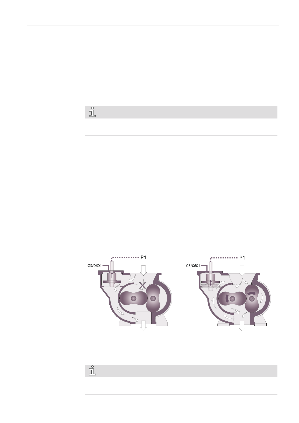
2.1 Operating Principle .......................................................................................................... 6
2.2 Application....................................................................................................................... 6
2.3 Shaft Sealing Variants....................................................................................................... 6
2.3.1 Mechanical Seal..................................................................................................... 7
2.3.2 Lip Seals (Optional) ............................................................................................... 7
2.4 Accessories....................................................................................................................... 7
2.4.1 Resistance Thermometer ....................................................................................... 7
2.4.2 Active Bypass Valve...............................................................................................7
2.5 Explanation of ATEX Classification.................................................................................... 8
2.6 Safety concept ................................................................................................................. 8
2.6.1 ATEX Classifications and Associated Accessories .................................................... 9
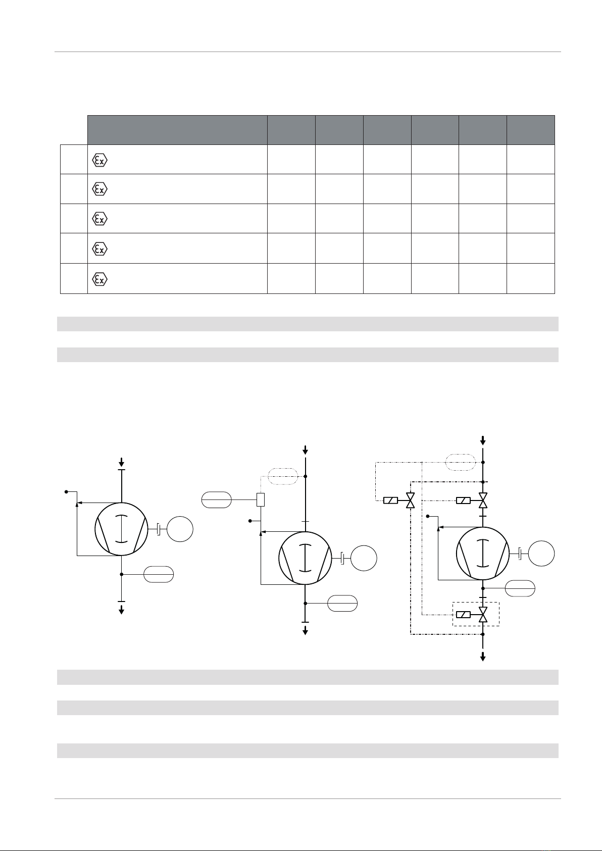
2.6.2 P&ID "Piping and Instrumentation Diagram" ........................................................ 9
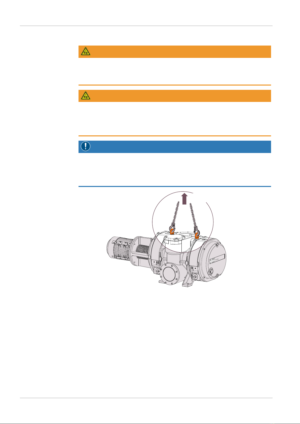
3 Transport ..................................................................................................................................10
4 Storage .....................................................................................................................................10
5 Installation................................................................................................................................11
5.1 Installation Conditions...................................................................................................... 11
5.2 Connecting Lines / Pipes .................................................................................................. 12
5.2.1 Gas Flow Variants.................................................................................................. 12
5.2.2 Suction Connection ............................................................................................... 12
5.2.3 Discharge Connection ........................................................................................... 13
5.2.4 Pneumatic Connection (with Active Bypass Valve only) ......................................... 13
5.3 Earth Connection ............................................................................................................. 14
5.4 Filling Oil.......................................................................................................................... 14
5.5 Fitting the Coupling ......................................................................................................... 16
5.6 Electrical Connection ........................................................................................................ 17
5.6.1 Wiring Diagram Three-Phase Motor...................................................................... 17
5.7 Electrical Connection of the Monitoring Devices............................................................... 19
5.7.1 Wiring Diagram Resistance Thermometer.............................................................. 19
5.7.2 Wiring Diagram Limit Switch ................................................................................. 20
5.8 Flowchart ......................................................................................................................... 22
6 Commissioning.........................................................................................................................23
6.1 Compression Chamber Flushing ....................................................................................... 24
7 Maintenance.............................................................................................................................25
7.1 Maintenance Schedule ..................................................................................................... 25
7.2 Oil Level Inspection.......................................................................................................... 26
7.3 Oil Colour Inspection ....................................................................................................... 26
7.4 Oil Change....................................................................................................................... 27
7.5 Coupling Maintenance ..................................................................................................... 30
7.6 Calibration Procedure of the Electrical Devices ................................................................. 30
7.6.1 Procedure A ..........................................................................................................30
7.6.2 Procedure I............................................................................................................30
8 Overhaul...................................................................................................................................31
9 Decommissioning.....................................................................................................................31
9.1 Dismantling and Disposal ................................................................................................. 31
10 Spare Parts................................................................................................................................32

Table of Contents
0870206364_WV1200-2400A_Ex_-0004_IM_en 3
11 Troubleshooting .......................................................................................................................32
12 Technical Data..........................................................................................................................34
13 Oil ............................................................................................................................................34
14 EU Declaration of Conformity...................................................................................................35

1 | Safety
4 / 36 0870206364_WV1200-2400A_Ex_-0004_IM_en
1 Safety
Prior to handling the machine, this instruction manual should be read and understood. If
anything needs to be clarified, please contact your Busch representative.
Read this manual carefully before use and keep for future reference.
This instruction manual remains valid as long as the customer does not change anything
on the product.
The machine is intended for industrial use. It must be handled only by technically trained
personnel.
Always wear appropriate personal protective equipment in accordance with the local
regulations.
The machine has been designed and manufactured according to state-of-the-art meth-
ods. Nevertheless, residual risks may remain. This instruction manual highlights potential
hazards where appropriate. Safety notes and warning messages are tagged with one of
the keywords DANGER, WARNING, CAUTION, NOTICE and NOTE as follows:
DANGER
... indicates an imminent dangerous situation that will result in death or serious injuries if
not prevented.
WARNING
... indicates a potentially dangerous situation that could result in death or serious injuries.
CAUTION
... indicates a potentially dangerous situation that could result in minor injuries.
NOTICE
... indicates a potentially dangerous situation that could result in damage to property.
NOTE
... indicates helpful tips and recommendations, as well as information for efficient and
trouble-free operation.

Product Description | 2
0870206364_WV1200-2400A_Ex_-0004_IM_en 5 / 36
2 Product Description
OFP
BPV IN
OSG ODP, MP
OFP
ODP, MP MTB
OSG
OUT1
BGC
BGCBGC
OR
OUT2
BGC
NP
EB
WV 2400 A
WV 2400 A
WV 2400 A with lip seals variant
(Optional)
TSA+/0101
GS/0601
PMC
ECP
PCY
BGC Barrier gas connection BPV Bypass valve or active bypass valve
EB Eye bolt ECP Earth connection (machine)
GS Limit switch (with active bypass valve only) IN Suction connection
MP Magnetic plug MTB Motor terminal box
NP Nameplate ODP Oil drain plug
OFP Oil fill plug OR Oiler (Optional)
OSG Oil sight glass OUT Discharge connection
OUT2 Lateral discharge connection (optional) PCY Pneumatic cylinder (with active bypass
valve only)
PMC Pneumatic connection (with active bypass
valve only)
TSA Resistance thermometer
NOTE
Technical term.
In this instruction manual, we consider that the term ‘machine’ refers to the ‘vacuum booster’.
NOTE
Illustrations
In this instruction manual the illustrations may differ from the machine appearance.

2 | Product Description
6 / 36 0870206364_WV1200-2400A_Ex_-0004_IM_en
2.1 Operating Principle
The machine works on the Roots blower principle.
The two oil housings (on each side) allow the lubrication of the gears, bearings and in
certain versions the oil lubricated mechanical seals.
A bypass valve (BPV) limits automatically the differential pressure between inlet and out-
let.
2.2 Application
The machine is intended for the suction of air and other dry, non-aggressive and non-
toxic gases.
Explosive gases and vapour mixtures can be drawn according to the scope of the Direct-
ive ATEX 2014/34/EU.
Depending on the equipment, the machine is intended for suction of explosive gases ac-
cording to the data given on the nameplate of the machine (NP), see Explanation of
ATEX Classification [►8].
Conveying of other media leads to an increased thermal and/or mechanical load on the
machine and is permissible only after a consultation with Busch.
The machine is intended for the placement in a potentially explosive environment ac-
cording to the data given on the nameplate of the motor and the nameplate of the ma-
chine (NP), see Explanation of ATEX Classification [►8].
In case Busch delivered the machine without motor and coupling, the following must be
observed:
• In regards to its explosive atmosphere protection class, the motor and the coup-
ling must have at least the same ATEX classification as the machine for the outside
area “Outside (o)”.
• The motor and the coupling do not require an ATEX certification when the ma-
chine ATEX classification corresponds to “Outside (o) No ATEX zone”.
The vacuum booster is used in combination with a backing pump in vacuum system.
The machine is suitable for continuous operation.
Permitted environmental conditions, see Technical Data [►34].

Product Description | 2
0870206364_WV1200-2400A_Ex_-0004_IM_en 7 / 36
2.3 Shaft Sealing Variants
2.3.1 Mechanical Seal
The shaft sealing consists, in standard execution, of a mechanical seal.
2.3.2 Lip Seals (Optional)
Optionally, the shaft sealing may consist of three lip seals. This variant requires an oiler
(OR) in order to continuously lubricate the sealing system.
2.4 Accessories
NOTE
Depending on the ATEX classification of the machine, some of the following accessories
may be mandatory, see ATEX Classifications and Associated Accessories [►9].
2.4.1 Resistance Thermometer
The resistance thermometer monitors the exhaust gas temperature.
Warning and trip signals must be set, see Wiring Diagram Resistance Thermometer [►19].
2.4.2 Active Bypass Valve
The active bypass valve allows the gas to flow (forced bypass) when the absolute inlet
pressure (P1) is above 100 hPa (abs.).
The active bypass valve is controlled mechanically by a double activated pneumatic cylin-
der.
A pressure switch/transmitter and a directional control valve (not delivered) must be installed to
control the active bypass valve, see Pneumatic Connection (with Active Bypass Valve only)
[►13].
The limit switch (GS/0601) detects the position of the active bypass valve. See Wiring
Diagram Limit Switch [►20].
X
P1
P1
GS/0601
GS/0601
P1 <100 hPa = free bypassP1 >100 hPa = forced bypass
- the active bypass valve is released
- the limit switch signal can be ignored
- the vacuum booster is running
- the active bypass valve is forced in high position
- the limit switch (GS/0601) validates the high
position of the bypass
- the gas flow goes through the bypass channel
- the vacuum booster does not operate
NOTE
The active bypass valve can be substituted by an external bypass (not delivered), see
P&ID "Piping and Instrumentation Diagram" [►9].

2 | Product Description
8 / 36 0870206364_WV1200-2400A_Ex_-0004_IM_en
2.5 Explanation of ATEX Classification
2.6 Safety concept
WARNING
Misinterpretation of the ATEX instructions.
Risk of severe injury!
Risk of explosion!
• Make sure that the recommendations described in this manual correspond to the
ATEX marking written on the nameplate (NP).
• If anything needs to be clarified, please contact your Busch representative.
The safety concept is based on the prevention of sparks and excessive temperatures by
means of various accessories.
The monitoring devices must be integrated into the system control such that operation
of the machine will be inhibited if the safety limit values are exceeded.
The limit values of each accessory are defined in the wiring diagram chapters, see Elec-
trical Connection of the Monitoring Devices [►19].
To have more details about the monitoring procedure, see Flowchart [►22].

Product Description | 2
0870206364_WV1200-2400A_Ex_-0004_IM_en 9 / 36
2.6.1 ATEX Classifications and Associated Accessories
The following table defines the obligatory accessories depending on the ATEX classifica-
tion.
(i) No ATEX zone
(o) II 3G Ex h IIC T4 Gc X
TSA+
/0101
ATEX
MOT IIC
ATEX
CPL ECP
X
A
B
C
D
ATEX
MOT IIB
(i) II 3G Ex h IIC T3, T4 Gc X
(o) II 3G Ex h IIC T4 Gc X
(i)
No ATEX zone
(o) II 2G Ex h IIB (or IIC) T4 Gb X
(i) II 2G Ex h IIB T3, T4 Gb X
(o) II 2G Ex h IIB (or IIC) T4 Gb X
X
X
BPV
E
(i) II 2G Ex h IIB T3, T4 Gb X
(o)
No ATEX zone X
X*
X*
X*
X
X
X
X
X
X
X
X
X
X
X
X
X
X
(X)
(X)
ATEX classification
* can be substituted by an external bypass
Active
BPV Active bypass valve or external bypass CPL Coupling
ECP Pump earth connection MOT Motor (IIB or IIC)
TSA Resistance thermometer
2.6.2 P&ID "Piping and Instrumentation Diagram"
TSA+
0101
IN
OUT
M
CPL
MOT
BPV
TSA+
0101
IN
OUT
M
CPL
MOT
BPV
PS/PSA
GS
0601
TSA+
0101
IN
OUT
M
CPL
MOT
BPV
PS/PSA
MV
MV
MV
P1
P1
P&ID - standard execution P&ID - with active bypass P&ID - with external bypass
P1 >100 hPa = active bypass forced open
P1 <100 hPa = active bypass free
P1 >100 hPa = external bypass open
P1 <100 hPa = external bypass closed
(not included in the scope of delivery)
(Optional)
External bypass open when P1 >100 hPa
(Normally open)
(Normally closed)
(Normally closed)
P1 >100 hPa = MOT state "OFF"
P1 <100 hPa = MOT state "ON"
P1 >100 hPa = MOT state "OFF"
P1 <100 hPa = MOT state "ON"
BPV Bypass valve CPL Coupling
GS Limit switch IN Suction connection
MOT Motor MV Solenoid valve (not included)
OUT Discharge connection PS/PSA Pressure switch/transmitter
(not included)
TSA Resistance thermometer

3 | Transport
10 / 36 0870206364_WV1200-2400A_Ex_-0004_IM_en
3 Transport
WARNING
Suspended load.
Risk of severe injury!
• Do not walk, stand or work under suspended loads.
WARNING
Lifting the machine using the motor eye bolt.
Risk of severe injury!
• Do not lift the machine using the eye bolt fitted to the motor. Only lift the machine as
shown.
NOTICE
In case the machine is already filled with oil.
Tilting a machine that is already filled with oil can cause large quantities of oil to in-
gress into the cylinder.
• Drain the oil prior to every transport or always horizontally transport the machine.
Machine weight:
see the technical data or the nameplate (NP)
• Check the machine for transport damage.
If the machine is secured to a base plate:
• Remove the machine from the base plate.
4 Storage
• Seal all apertures with adhesive tape or reuse provided caps.
If the machine is to be stored for more than 3 months:
• Wrap the machine in a corrosion inhibiting film.
• Store the machine indoors, dry, dust free and if possible in original packaging
preferably at temperatures between -20 ... 55 °C.

Installation | 5
0870206364_WV1200-2400A_Ex_-0004_IM_en 11 / 36
5 Installation
5.1 Installation Conditions
WARNING
The installation conditions are not respected in an ATEX environment.
Risk of severe injury!
Risk of explosion!
• Take care that the installation conditions are met.
NOTICE
Use of the machine outside of the permitted installation conditions.
Risk of premature failure!
Loss of efficiency!
• Take care that the installation conditions are fully complied with.
• Make sure that the environment of the machine complies with the ATEX classification
of the machine according to the data given on the nameplate of the motor and the
nameplate of the machine (NP).
• Make sure that the ambient conditions comply with the Technical Data [►34].
• Make sure to use a suitable backing pump, if necessary seek advice from your Busch
representative
If the machine is ATEX certified “Inside (i)”:
• Make sure that the vacuum booster is equipped either with an active bypass valve
or an external bypass, see Active Bypass Valve [►7].
• Make sure that the environmental conditions comply with the protection class of the
motor and the electrical instruments.
• Make sure that the installation space or location is vented such that sufficient cooling
of the machine is provided.
• Make sure that cooling air inlets and outlets are not covered or obstructed and that
the cooling air flow is not affected adversely in any other way.
• Make sure that the oil sight glass (OSG) remains easily visible.
• Make sure that enough space remains for maintenance work.
• Make sure that the machine is placed or mounted horizontally, a maximum of 1° in
any direction is acceptable.
•
Make sure that the machine is secured either from the four feet or from the discharge flange.
• Check the oil level, see Oil Level Inspection [►26].
• Make sure that all provided covers, guards, hoods, etc. are mounted.
If the machine is installed at an altitude greater than 1000 meters above sea level:
• Contact your Busch representative, the motor should be derated or the ambient
temperature limited.
If additional electrical components not included in scope of delivery should be added:
• Make sure that they have a better or equal ATEX classification than that of the
machine, see the ATEX marking on the nameplate (NP).
For classification type “E” (see ATEX Classifications and Associated Accessories [►9]):
• Make sure that the installation space or location is ventilated enough in order to
prevent the formation of an explosive area.

5 | Installation
12 / 36 0870206364_WV1200-2400A_Ex_-0004_IM_en
5.2 Connecting Lines / Pipes
WARNING
The connection lines can build up an electrostatic charge.
Risk of severe injury!
Risk of explosion!
• The connection lines must be made out of conductive material or provisions must be
made against creating an electrostatic charge.
• Remove all protective covers before installation.
• Make sure that the connections are gas tight.
• Make sure that the connection lines cause no stress on the machine‘s connection; if
necessary use flexible joints.
• Make sure that the line size of the connection lines over the entire length is at least as
large as the connections of the machine.
In case of very long connection lines it is advisable to use larger line sizes in order to
avoid a loss of efficiency. Seek advice from your Busch representative.
5.2.1 Gas Flow Variants
The machine can be installed in different ways:
Lateral discharge (Optional)Vertical gas flow
(In some specific cases, other gas flow variantes may apply)
5.2.2 Suction Connection
WARNING
Unprotected suction connection.
Risk of severe injury!
• Do not put hand or fingers in the suction connection.
NOTICE
Ingress of foreign objects or liquids.
Risk of damage to the machine!
If the inlet gas contains dust or other foreign solid particles:
• Install a suitable filter (5micron or less) upstream from the machine.
Connection size(s):
– DN160, DIN 28404
Depending on the specific order, other connection dimensions may apply.

Installation | 5
0870206364_WV1200-2400A_Ex_-0004_IM_en 13 / 36
5.2.3 Discharge Connection
Connection size(s):
– DN100, DIN 28404 for WV 1200/1800 A
– DN160, DIN 28404 for WV 2400 A
Same connection size for lateral discharge (OUT2)
Depending on the specific order, other connection dimensions may apply.
• Make sure that the discharged gas will flow without obstruction. Do not shut off or
throttle the discharge line or use it as a pressurised air source.
If the resistance thermometer (TSA+/0101) is delivered separately:
• Make sure to respect the distance between the discharge connection and the res-
istance thermometer position according to the illustration below.
max. 50 mm
TSA+/0101
OUT
5.2.4 Pneumatic Connection (with Active Bypass Valve only)
Pneumatic connections (PMC)
• Connect the two pneumatic connections to a 4/2-way-pneumatic valve (see scheme
below).
• Provide a suitable directional control valve enables to activate the pneumatic cylinder
when the pressure "P1" is reached.
P1 P1
P1 >100 hPa = forced bypass P1 <100 hPa = free bypass
Connection size (PMC):
– 2 x Ø6 (fitting)
• Make sure that the supply air pressure is between 2 ... 6 bar.

5 | Installation
14 / 36 0870206364_WV1200-2400A_Ex_-0004_IM_en
5.3 Earth Connection
In order to prevent the machine from creating an electrostatic charge:
• Connect the earth connection of the machine (ECP)
Earth connection of
the machine (ECP)
5.4 Filling Oil
NOTICE
Use of an inappropriate oil.
Risk of premature failure!
Loss of efficiency!
• Only use an oil type which has previously been approved and recommended by
Busch.

Installation | 5
0870206364_WV1200-2400A_Ex_-0004_IM_en 15 / 36
For oil type and oil capacity see Technical Data [►34] and Oil [►34].
1
5
3
MAX
MIN
2
Busch Oil
Busch Oil
4
Check oil level
Fill up until the oiler (OR)
is at least two thirds full
Oil filling at the motor side
With lip seals variant only
(Optional)
With lip seals variant only
(Optional)
1
4
3
MAX
MIN
2
Busch Oil
Check oil level
Oil filling at the gear side

5 | Installation
16 / 36 0870206364_WV1200-2400A_Ex_-0004_IM_en
When the oil filling is achieved:
• Write down the oil change date on the sticker.
Last oil change
__ / __ / ____
Oil type see nameplate
Change interval see
instruction manual
If there is no sticker (part no. 0565 568 959) on the machine:
• Order it from your Busch representative.
5.5 Fitting the Coupling
E
Coupling hub (machine side) Coupling hub (motor side)Coupling spider
Radial screw
Max. admissible
torque: 10 Nm
Machine type Coupling size Value “E” (mm)
WV 1200 A ROTEX® 24 18
WV 1800 A
WV 2400 A ROTEX® 38 24
In case of a machine delivery without motor:
• Make sure that the ATEX marking of the coupling corresponds to the ATEX classi-
fication of the machine.
• Fit the second coupling hub on the motor shaft (separately delivered).
• Axially adjust the hub in such a way until value "E" is reached.
• When the coupling adjustment is done, lock the coupling hub by tightening the
radial screw.
• Mount the motor on the machine by including the coupling spider.
For further coupling information, go to www.ktr.com and download the instruction
manual of the ROTEX® coupling.

Installation | 5
0870206364_WV1200-2400A_Ex_-0004_IM_en 17 / 36
5.6 Electrical Connection
DANGER
Live wires.
Risk of electrical shock.
• Electrical installation work must only be executed by qualified personnel.
• Make sure that the power supply for the motor is compatible with the data on the
nameplate of the motor.
• The electrical installation must comply with applicable national and international
standards.
• Provide a lockable disconnect switch on the power line so that the machine is com-
pletely secured during maintenance tasks.
• Provide an overload protection according to EN 60204-1 for the motor.
• Make sure that the motor of the machine will not be affected by electric or electro-
magnetic disturbance from the mains; if necessary seek advice from Busch.
• Connect the protective earth conductor.
• Electrically connect the motor.
NOTICE
Incorrect connection.
Risk of damage to the motor!
• The wiring diagrams given below are typical. Check the inside of the terminal box for
motor connection instructions/diagrams.
5.6.1 Wiring Diagram Three-Phase Motor
NOTICE
Incorrect direction of rotation.
Risk of damage to the machine!
• Operation in the wrong direction of rotation can destroy the machine in a short time!
Prior to start-up, ensure that the machine is operated in the right direction.
The intended rotation direction of the motor is defined by the specific instruction label
stuck on the machine.
• Jog the motor briefly.
• Watch the fan wheel of the motor and determine the direction of rotation just before
the fan wheel stops.
If the rotation of the motor must be changed:
• Switch any two of the motor phase wires.

5 | Installation
18 / 36 0870206364_WV1200-2400A_Ex_-0004_IM_en
Delta connection (low voltage): Star connection (high voltage):
Double star connection, multi-voltage
motor with 9 pins (low voltage):
Star connection, multi-voltage motor
with 9 pins (high voltage):
Double star connection, multi-voltage
motor with 12 pins (low voltage):
4
4
4
Star connection, multi-voltage motor
with 12 pins (high voltage):
4
4
4
Delta connection, multi-voltage motor
with 12 pins (middle voltage):
4
4
4

Installation | 5
0870206364_WV1200-2400A_Ex_-0004_IM_en 19 / 36
5.7 Electrical Connection of the Monitoring Devices
NOTE
In order to prevent potential nuisance alarms, Busch allows that the control system is
configured with a time delay of 2 seconds.
NOTE
The accessories below are considered as standard.
If other specific components should be used, refer to the instruction manual of the ac-
cessory in question.
WARNING
If the monitoring sensors are not used.
Risk of explosion!
• Always use the mandatory monitoring sensors.

5 | Installation
20 / 36 0870206364_WV1200-2400A_Ex_-0004_IM_en
5.7.1 Wiring Diagram Resistance Thermometer
Part no.:
0651 536 445 (without transmitter)
Supplier reference:
PT100: Albert Balzer AG
ref. TFE-B D A B
Maintenance procedure:
Procedure A [►30]
P&ID position:
TSA+/0101 “exhaust gas temp.”
Wiring without transmitter:
1
2
3
4
1 and 2 = Red ; 3 and 4 = White
Electrical data:
Ui=30VDC; Ii=100mA; Pi=750mW; Li=0.015mH; Ci=280pF
Warning signal: a warning signal can be set prior the trip signal.
Trip signal: T3 (i) / T4 (o)
Ttrip (TSA+/0101) = 150°C (for WV 1200 and 1800 A)
Ttrip (TSA+/0101) = 160°C (for WV 2400 A)
Trip signal: T4 (i) / T4 (o) (specific conditions only)
Ttrip (TSA+/0101) = 125°C (for WV 1200, 1800 and 2400 A)
Part no.:
0651 536 447 (with transmitter)
Supplier reference:
PT100: Albert Balzer AG
ref. TFE-B D A B
Transmitter: Endress+Hauser
ref. TMT 187-B41FIA
Maintenance procedure:
Procedure A [►30]
P&ID position:
TSA+/0101 “exhaust gas temp.”
Wiring with transmitter:
2
1
+
-
1
2
3
4
5
6
+
-
1 = Brown ; 2 = Blue
Electrical data:
Ui=30VDC; Ii=100mA; Pi=760mW; Li=0µH; Ci=0pF
4 ... 20 mA ► 0 ... 250 °C
Warning signal: a warning signal can be set prior the trip signal.
Trip signal: T3 (i) / T4 (o)
Ttrip (TSA+/0101) = 150°C ► 13.6 mA (for WV 1200 and 1800 A)
Ttrip (TSA+/0101) = 160°C ► 14.24 mA (for WV 2400 A)
Trip signal: T4 (i) / T4 (o) (specific conditions only)
Ttrip (TSA+/0101) = 125°C ► 12 mA (for WV 1200, 1800 and 2400 A)
This manual suits for next models
2
Table of contents