Butts of Bawtry TCS0022 Datasheet

22" Semi Automatic Tyre Changer
User Instructions & Parts List
TCS0022

Table of Contents
1. Introduction:..............................................................................................................................................1
2. Warning label and sticking position:.........................................................................................................1
3. Technical data:...........................................................................................................................................1
4. Transport:..................................................................................................................................................1
5. Unpacking:................................................................................................................................................1
6. Workplace requirements:...........................................................................................................................2
7. Product diagram........................................................................................................................................2
8. Assembly procedure:.................................................................................................................................2
9. Electric& Pneumatic link up.....................................................................................................................2
10. To perform preliminary operation tests:..................................................................................................3
10.1. To loosen the tyre bead:................................................................................................................3
10.2. Clamping the tyre:........................................................................................................................3
10.3. Demounting the tyre:....................................................................................................................4
10.4. Mounting the tyre:........................................................................................................................4
10.4.1 Checking tyre and wheel rim......................................................................................................4
10.4.2 Mounting the tyre.......................................................................................................................4
10.5. Inflating the tyre:..........................................................................................................................5
10.5.1. Inflation without tubeless tyre inflation device:........................................................................5
10.5.2. Inflation with tubeless tyre inflation device:.............................................................................5
12. Removing:...............................................................................................................................................6
13. Maintenance:...........................................................................................................................................6
14. Trouble shooting table:.........................................................................................................................8
15. Exploded drawing:..................................................................................................................................9
16. Circuit diagram: ....................................................................................................................................20
16. Pneumatic drawing:...............................................................................................................................20

U200 Series-A
1
Tyre Changer
Warning:This instruction is important for the machine, read carefully before installation and use, also it
is important for safe use and maintenance of machine. Please keep this manual kindly in order to use and
repair it further。
1. Introduction:
Application Range: The semi-automatic tyre changer is especially designed for demounting / mounting
tyres.
Caution: Use only for purpose for which it is designed, don't use it for other purposes. Manufacturer
shall not be liable for any damage or injury caused by failure to
comply with these regulations.
Use of this machine is especially reserved to trained and qualified
professional persons. Any changes on this machine without
manufacturer’s permission may cause the malfunction and damage to
machine, manufacturer can cancel warranty coverage for above. If some
parts are damaged due to some reasons, please replace them according to
the spare parts list. (Attention: deadline of warranty is one year after
sale).
2. Warning label and sticking position:
01 Don’t put hands under the mounting head during operation;
02 Don’t put hands between the jaws during operation;
03 Don’t put hands in the tyre bead when demounting;
04 Make sure the system is equipped with a good grounding circuit;
05 Don’t put feet between the bead breaking arm and the body during operation;
06 Warning instructions;
3.Technical data:
4. Transport:
When transporting the machine, it must be handled with a forklift truck
with the forks. Positioned as show as in the Fig1.
5. Unpacking:
Pull out the nail which is nailed on the plate with tip jaw, unpack the carton
and plastic cover. Check to make sure all parts shown on the spare parts list are
included. If any parts are missing or broken, please contact the manufacturer or
dealer ASAP.
Type
200/600
201
201A
202
203
203A
External Locking
Rim Dimensions
10~17"
10~20"
12~23"
Internal Locking
Rim Dimensions
12~20"
12~24"
14~26"
Max. Wheel
Diameter
960mm(20")
1040mm(41")
1143mm(45")
Max. Wheel Width
330mm(13")
355mm(14")
16"
Max. Working
Pressure
8-10Bar
Power supply
110V-1ph /220V-1ph / 380V-3ph
Motor power
0.75/0.55/1.1kw
Max. Rotating
Torque (Turntable)
1078Nm
Overall Dimension
96X76X93cm
113X90X103cm
Noise Level
75Db
Fig 1

2
6. Workplace requirements:
Choose workplace in compliance with safety regulations. Connect power supply and air source according to
manual, workplace must have good air condition; in order to make the machine run well,
its workplace requires at least clear space from each wall shown as Fig 2. If installing it
outdoor, it must be protected by roof against rain and sunshine.
Warning: the machine with motor must not be operated in explosive
atmosphere.
7. Product diagram
Operation and function label:
8. Assembly procedure:
1. Prepare the tools and unscrew the nuts at the bottom, position the machine and calibrate it with the
horizontal rule. Mount the machine with the screws. Make sure the system is equipped with a good grounding
circuit.And have operations for skid prevention.
2. Unscrew the nut A on the body B as shown in Fig 4. Lift the column C, mount it on the body using the nut A
through the bolt located on the body B. If the column becomes loose, screw them immediately. Otherwise damage to
the tyre may happen.
9. Electric& Pneumatic link up
1) Depress the Jaw Clamping pedal (G, Fig 3) to ensure that the jaws on the turntable do not open unexpectedly
to avoid injury caused by the accident.
A
Adjustable handle
H
Bead breaker pedal
B
Swing arm
I
Lift lever
C
Vertical arm
J
Rubber buffer
D
Jaw
K
Bead breaker arm
E
Turntable
L
Mounting head
F
Reverse pedal
M
Column
G
Jaw Clamping pedal
N
Locking handle
Fig 3
Air blast pedal
Turntable reverse pedal
Jaw clamping pedal
Bead breaker pedal
Fig2

U200 Series-A
3
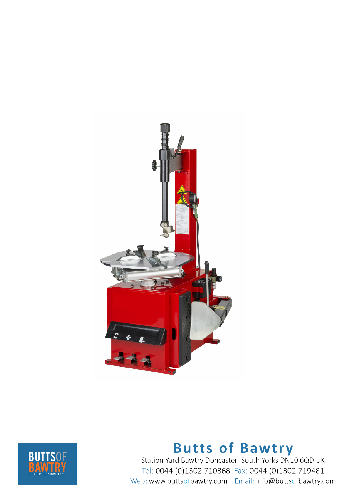
2) Connect the inflation gun to its connector. (Fig 3)
3) Connect tyre changer to compressed air network with air hose of inside
diameter of 7-8 mm, air pressure of 8~10 bar is recommended.
4) Air pressure is not permitted to surpass 10 bar, otherwise, manufacturer
can cancel the warranty coverage.
Caution: the pressure of compressed air network is not permitted to
surpass 10 bar. Please install pressure-adjusting valve when it is more than
10 bar. Before making any electric link up, check to be sure that the main
voltage correspond to what is stamped on the voltage tag. It is essential that
the system is equipped with a good grounding circuit. The machine must be
connected to a power supply line circuit bracket set for 30A.
Caution: The rated power supply of tyre changer is given on rear panel, please check the voltage.
However minor, any operations on electrics must be done only by professional persons.Manufacturer shall
not be liable for any damage caused by failure to comply with the regulations.
Warning: Keep hands and your body away from moving parts of tyre changer. Do not wear necklace,
bracelet or loose clothing. Unreadable and missing labels must be replaced at once. Don't use this machine if
any warning labels missed. Keep labels clear for operator.
10. To perform preliminary operation tests:
Check whether the tyre changer runs well or not after connection finished:
Depress the reverse pedal to turn the turntable in clockwise direction.
Push the reverse pedal up to turn the turntable in anti-clockwise direction.
Depress the bead breaker pedal to open the bead breaker arm. Loosen it to turn the bead breaker arm back.
Depress the jaw clamping pedal completely to open the jaws on the turntable, depress it once again to close the
jaws. When the pedal is in the middle position, the jaws are in the static status.
Tyre changer operation is consisted of three parts:
1)Demounting the tyre bead
2)Demounting the tyre
3)Mounting the tyre
Caution: Before any operations, don’t wear loose clothing and wear protective hat, gloves, and
skid-proof shoes. Take off all the weights on both sides of wheel rim before operation. Ensure to exhaust the
air in the tyre completely, and remove all the wheel weights from the rim.
10.1. To loosen the tyre bead:
Be careful when loosening tyre. Bead breaker arm will move rapidly with
powerful force when depressing the bead breaker pedal, it may crash things in
its working area.
1) Deflate the tyre completely take off the core of valve stem;
2) Close the four jaws on the turntable to avoid conflict. If jaws open, it
may scratch hands, so don't touch the bead when loosening.
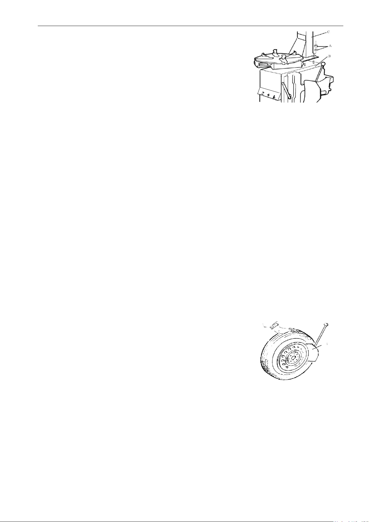
3) Open the bead breaker arm by hands by pushing it towards the outside,
place the tyre against the rubber buffer. Bring the paddle against the bead about
10mm from the edge of the rim shown as Fig 5.
Caution: Place the paddle against the tyre bead.
4) Depress pedal (H, Fig 3) to push paddle into tyre. Repeat the above operations on different positions around
the tyre and both sides of tyre until tyre is released completely.
10.2. Clamping the tyre:
1) Remove all the weights on the wheel rim;
2) Lubricate the tyre bead;
3) Swing the swing arm to non-working position.
4) Secure the wheel rim on the turntable from inside or outside.
Don't put your hands under the wheel while clamping the wheel rim.
Put the tyre on the center of the turntable.
Fig4
Fig5
F

4
Check to make sure the wheel firmly secured by the four jaws.
a- to clamp the wheel from outside (Tyre Diameter From 10″To 21″):
Depress the jaw clamping pedal halfway down to position the four jaws, put the tyre on turntable, and depress
the jaw clamping pedal until the wheel is secured by the jaws.
b- to clamp the wheel from inside (Tyre Diameter From 12”To 24”):
Depress the jaw clamping pedal to close the four jaws on the turntable. Put the tyre on the turntable and depress
the jaw clamping pedal to open the jaws, thereby lock the wheel in place.
10.3. Demounting the tyre:
1) Swing the swing arm on the column to the working position.
Don't put your hands on the wheel rim to avoid injury during this operation.
2) Lower the vertical arm until the mounting head rests next to the wheel and on
the top of tyre. Then lock the vertical arm in position using the locking handle. The
mounting head can raise 2mm-3mm automatically from the edge of the wheel rim.
3) Insert the lifting lever between the tyre bead and the front section of the
mounting head, and move the tyre above the mounting head as shown as Fig 6.
Note: In order not to damage the inner tube, it is recommended to perform this step with the inner tube
valve stem positioned about 10 cm to the right of the mounting head.
With the lifting lever held in position shown as Fig 6, rotate the turntable in a clockwise direction by fully
depressing the reverse pedal. Continue until the tyre is completely separated from the wheel rim.
To prevent accident, keep hands and other parts of your body away from moving devices during operation.
Note: The tyre can be slid out easily from the mounting head due to hardness. In order to prevent it, with the
lifting lever held in position shown as Fig 6, rotate the turntable about 1~2 cm in anti-clockwise direction before
rotating in clockwise direction.
4) Remove the inner tube if there is one.
5) Repeat the step 3 for the other side of the tyre.
6) Swing the swing arm to the non-working position. Remove the tyre from the
wheel rim.
10.4. Mounting the tyre:
10.4.1 Checking tyre and wheel rim
Caution: Check to make sure that the tyre and the wheel rim are of same size, it can prevent burst of the
tyre during inflating and mounting.
Check as follows:
- No damage for tyre and tyre components, don't use it if some defects on the tyre appear.
- No convex and concave defects on the wheel rim.
Note: Especially for alloy wheel rim, it may have some micro inner cracks caused by concave defects,
they bring in the danger to operators or the damage to the wheel rim.
The tyre and the wheel rim must be of the same size.
Note: The diameter of the wheel rim is stamped on itself, so is the tyre. If you are not sure, don't mount the
tyre.
10.4.2 Mounting the tyre
1) Lubricate the tyre bead and the wheel rim with the lubrication recommended by manufacturer.
2) Clamp the wheel rim according to the section of “clamping the tyre”if the tyre is removed from the
turntable.
3) Swing the swing arm on the column to the working position. Don't put your hands on the wheel rim to avoid
injury during this operation.
4) Place the mounting head above the edge of the wheel rim with hands. Lock the vertical arm as described as
step 2 in the section of “demounting the tyre”.
5) Move the tyre so that the bead passed below the front section of the mounting head and is brought up against
the edge of the rear section of the mounting head. (Fig 7)
Note: If the tyre doesn't have inner tube, make the valve stem and mounting head in the same line. Keep
Fig 6
Fig 7

U200 Series-A
5
the tyre bead pressed down into the wheel rim channel with hands. Then, depress the pedal to rotate the
turntable in clockwise direction. Continue this process throughout the entire circumference of the wheel rim
and tyre.
To prevent accident, keep hands and other parts of your body away from moving devices.
6) Insert the inner tube if there is one.
7) Repeat the steps above for the other side of the tyre. Swing the swing arm to non-working position.
8) Depress the pedal, remove the tyre from the turntable.
Note: The turntable is always rotating clockwise during mounting or demounting; anti-clockwise rotating is
just for correcting operation.
10.5. Inflating the tyre:
10.5.1. Inflation without tubeless tyre inflation device:
Importance:
It is very dangerous during inflating operation, take carefully and comply
with instruction.
A burst of the tyre can cause serious injury or even death to the operator.
There is a decompression valve which restricts pressure not to surpass
3.5bar on the tyre changer, but the possibility of burst still exists. Please don’t
underestimate the danger.
Tyre may burst caused by following:
1) The wheel rim and the tyre are not of the same size;
2) The tyre or the wheel rim is damaged;
3) The pressure of tyre inflation is over the max. Pressure recommended by manufacturer;
4) Fail to comply with the safety regulation;
Operate as follows:
1) Remove the valve cap from the valve stem;
2) Attach the air gauge nozzle to the tyre valve stem with the locking lever in the “UP”position. Check to
make sure the nozzle is pressed down completely over the threads of the valve stem.
3) Check to make sure that the tyre and the wheel rim are of the same size;
4) Lubricate both the tyre bead and the wheel rim, additional lubrication is required if needed;
5) Inflate the tyre with break, while inflating, check the pressure listed on the pressure gauge, also check
whether the bead is fixed or not. Repeat operation above until the bead is secured; you need take special steps when
inflating convex rim or double convex rim;
6) Continue inflating and check the air pressure frequently. Once the proper air pressure has been reached,
disconnect the nozzle from the valve stem and screw a valve cap onto the stem.
Note: Never exceed the max. inflation pressure given by the tyre manufacturer.
Keep hands and your body away from inflating tyres.
Only specially trained persons are allowed to perform the operations, do not allow other to operate or be near
the tyre changer.
10.5.2. Inflation with tubeless tyre inflation device:
1) The tubeless tyre inflation device is used during bead-seating operation and during inflation in place of the
airline gauge.
2) Disconnected from any power sources.
3) Before operating, it should be to check the device correctly:
-Press the inflating pedal down to the middle position. the inflating head should give air.
-Press the inflating pedal all the way down. A strong air blast should come from the holes in the four locking
sliders.
Bead seating and inflating note: a wheel can explode if:
a. The diameter of the rim is not exactly the same at the tyre’s.
b. The rim or tyre are defective.
NOTE: Before any installation work, check to make sure that the tyre changer is disconnected from any
Fig 8

6
power sources.
c. If the recommended pressure is exceeded during bead seating.
d. The tyre is inflated to a pressure higher than the maximum recommended by the manufacturer.
e. The operator does not observe the requisite safety regulations.
4) Tube tyres
a. Remove the valve stem.
b. Clip the valve onto the inflator chuck , making sure it is properly connected.
c. Make a last check to be certain that tyre and rim diameter correspond.
d. Check to be certain that rim and beads are sufficiently lubricated.
If necessary lubricate some more.
e. Press the pedal down to the middle position to start inflation.
f. Release frequently the inflating pedal to check pressure on the manometer.
Introduce more air little by little until the correct pressure is reached.
5) Tubeless tyres inflating
NOTE: When inflating tubeless tyre using a strong jet of air, the wheel must be clamped from the inside
of the rim.
a. Remove the valve stem.
b. Clip the valve onto the inflator chuck making sure it is properly connected.
c. Make a last check to be certain that tyre and rim diameter correspond.
d. Check to be certain that rim and beads are sufficiently lubricated. If necessary lubricate some more.
e. Press the pedal down to the middle position.
f. If the bead of the tyre is not well seated, due to a strong bead, lift tyre manually until the upper bead seals
against the rim, then press the pedal all the way down. A strong jet of air will be released through the nozzles in the
slides and this will help the bead seal.
CAUTION: Always keep hands and body back from inflating tyre.
g. Release the tyre , set the pedal back to the middle position and continue to inflate the tyre to the required
pressure.
NOTE:
1) Failure to follow all warnings and instructions may lead to serious personal injury or death to operator or
bystander. NEVER exceed 3.5 bar (50 psi) when seating beads or inflating tyres.
2) If a higher tyre inflation pressure is required, remove the wheel from the tyre changer and continue the
inflation procedure with the wheel inside a special protection cage. NEVER exceed the maximum inflation pressure
given by the tyre manufacturer.
3) Always keep hands and entire body back from inflating tyre.
4) Only specially trained persons are allowed to perform these operations. do not allow others to operate or be
near the tyre changer.
12. Removing:
If the machine needs to be stored for a long time, disconnect power supply and air source. Lubricate all parts
what they need. Empty all the oil and water in the box. Put on the plastic cover to prevent dust.
13.Maintenance:
Caution: only the professional persons can do the maintenance.To
prolong the machine's life, maintain it timely according to the manual.
Otherwise, it will impact the reliability of the machine or even cause injury to
operator and others nearby.
Caution: before performing any maintenance, disconnect the tyre changer
from the electric power supply and air source, and depress the bead breaker
pedal for 3~4 times to evacuate all compressed air from the machine. Damaged
parts must be replaced by professional persons with the spare parts provided
by manufacturer.
Clean the machine once everyday after work. Clean the dirt on the turntable with diesel oil once per week and
lubricate the slides and jaws.8
Fig 9
Fig 10
ED

U200 Series-A
7
Empty water in the air filter once every day to ensure the performance for the cylinder. following maintenance
must be done at least once per month: check oil level in oil fog maker, please top up with SAE30# oil if need,
depress pedal for locked tyre 5-6 times ,check whether oil in oil fog maker was leakage, continued operation,
depress twice every time, drop down a dripping oil, otherwise adjust screw(E) that controlled oil enter with minus
screwdriver. (Fig 10)
Note: After the first 20 days of use, retighten the jaws with tightening screws B. (Fig 11)
Note: in the event of a loss of power, check to see if the belt is tight. To do so,
remove the left side of the cover by unscrewing the screws. Tighten the belt, using
the adjusting screws located on the motor support. (Fig 12)
Caution: please disconnect the machine from power supply and air source.
Note: Adjust the vertical arm when it can not be locked or it can not be
complied with the working requirements on distance of 2mm with the mounting
head, please adjust it according to Fig 13.
In order to achieve the reliability of jaws and bead breaker arm, operate as
follows to keep their valves clean.
1. Remove the left side of the cover by unscrewing the two screws;
2. Loosen the valve silencers (A) which belong to jaw clamping pedal and bead breaker pedal;
3. Clean the silencers with compressed air, please replace it referring to the spare parts list if it is damaged. (Fig
14)
Fig11
Fig 12
Fig 13
Fig 14

8
14. Trouble shooting table:
Problem
Reason
Solution
The turntable rotate just in one
direction or can’t rotate
Damaged switch
Replace it.
Damaged belt
Replace it.
The Motor’s malfunction
Check the cable or wire;
Replace the motor if damaged.
The jaws delay to open/close;
the turntable can’t lock or lock
incorrectly
Leakage ofAir network
Check all the parts on the air
network.
The cylinder can’t work.
Replace the cylinder piston.
Worn jaws
Replace the jaws.
Broken washers of the chuck
cylinder
Replace it.
The mounting head always
touches the rim during operation.
The locking plate incorrectly
adjust or unqualified.
Replace or adjust it.
Screws on the chuck loose;
the locking plate can’t be locked
Tighten the screws; replace the
plate.
The bead breaker arm and jaw
clamping arm can’t turn back to the
original position.
Bad pedal spring
Replace it.
The bead breaker operates
difficultly.
Jammed silencer
Clean it or replace it.
The washer on the bead
breaker cylinder is broken.
Replace it.

U200 Series-A
9
15. Exploded drawing:
1
Body
2
Front cover
3
Left cover
4
Screw M6*55
5
Flat washer φ6*14*1.2
6
Screw M8*25
7
Spring washer φ8
8
Flat washer φ8*17*1.5
9
Nut M8
10
Rubber buffer
11
Screw M6*40
12
Lifting lever
13
Spring
14
Rubber support
15
Box
16
Rubber foot
17
Screw M8*20
18
Screw M8*25
19
Screw M10*55

10
101
vertical column
118
locking plate
102
column pin
119
horizontal arm
103
screw M14*30
120
hexagonal vertical arm
104
flat washer φ14.5*47*10
121
buffer bush
105
adjust handle
122
pulley
106
locking block handle
123
mounting head
107
locking block support
124
pin
108
cone washer
125
screw M10*25
109
spring washer φ8
126
flat washer
110
screw M8*25
127
screw M12*16
111
locking block
128
flat washer φ10*20*2
112
nut M12*1.75*7
129
spring washer φ10
113
screw M12*30
130
nut M10
114
screw M8*50
131
complete mounting head
115
knob
132
Mounting head 3#
116
plastic cover
117
spring

U200 Series-A
11
701
air gauge
702
hose
703
nut
704
union 1/4-1/4
705
flat washer φ13
706
pressure reducer
707
L-union 1/4-φ8
708
hose 5*8
801
relief pressure filter
802
quick nozzle
803
L-union
804
oil fog maker
805
hose 5*8
806
big T-joint
807
union 1/4-1/4
808
hose 5*8
809
union 1/8-φ8
810
manometer

12
201
turntable
221
cylinder rod
202
slide
222
flange without handle
203
jaw
223
union 1/8-φ8
204
turntable washer
224
V-seal UHS-20*28*7.5
205
spring washer φ16
225
O-seal 63*2.65
206
screw M16*40
226
piston
207
cap
227
flat washer φ12*25*2
208
control plate
228
nut M12*7*1.5
209
washer
229
clamping cylinder
210
retainer ring φ65
230
O-seal 20*2.65
211
connecting rod
231
flange with handle
212
slide guide with pin
232
L-union 1/8-φ8
213
flat washer φ12*25*2
233
self-locking nut M8
214
retainer ring φ12
234
complete clamping cylinder
215
screw M12*80
235
complete turntable Φ540
216
spring washer φ12
217
flat washer φ12*30*3
218
slide guide
219
spacer bush φ20
220
tightener

U200 Series-A
13
301
screw M14*30
316
screw M12*100
302
self-locking nut M6
317
self-locking nut M16
303
L-union 1/4-φ8
318
guide belt
304
nut M16*1.5
319
spring washer φ14
305
flat washer φ16*28*2
320
retainer ring φ16
306
O-seal 16*2.65
321
flat washer φ16*28*2
307
O-seal 20*2.65
322
bead breaker
308
O-seal 180*3.5
323
pin
309
bead breaker cylinder lid(front)
324
rotating pin
310
bead breaker rod
325
flat washer φ12*25*2
311
V-seal 185*168*11.5
326
self-locking nut M12
312
piston
327
flat washer φ8*30*3
313
bead breaker cylinder
328
spring washer φ8
314
screw M6*20
329
screw M8*20
315
shovel
330
union 1/8-φ8
331
complete bead breaker cylinder

14

U200 Series-A
15
401
pedal
431
screw M6*20
402
pedal
432
screw M4*30
403
pedal
433
flat washer φ4
404
twist spring
434
self-locking nut M6
405
screw M8*20
435
screw M4*16
406
connecting rod
436
flat washer φ4
407
switch handle
437
switch
408
tap screw ST2.9*12
438
nut M4
409
cam cover
439
switch cover
410
switch support
440
complete 5-way valve
411
flat washer
441
complete 5-way valve
412
cam
442
hose 5*8
413
spring
443
hose 5*8
414
pedal support
444
hose 5*8
415
self-locking nut M4
445
hose 5*8
416
flat washer φ4
446
L-union 1/8-φ8
417
screw M4*30
447
spacer
418
retainer ring φ12
448
O-seal 12*20*4
419
flat washer φ12*25*2
449
5-way valve
420
pedal shaft
450
valve cover
421
self-locking nut M8
451
tap screw ST2.9*16
422
flat washer φ8*17*1.2
452
O-seal 12*20*4
423
self-locking nut M8
453
silencer 1/8
424
connecting rod
454
L-union 1/8-φ8
425
screw M8*50
455
hose 5*8
426
nut M8
456
hose 5*8
427
screw M6*16
457
T-union 1/8-2*φ8
428
flat washer φ6*12*1
458
valve pole
429
screw M6*20
459
wire 3*1.5
430
flat washer φ6*12*1
460
5-way valve

16
501
bottom cover
521
O-seal φ27.8*3.1
502
bearing 30204
522
seal
503
seal φ20*35*8
523
self-locking nut M6
504
pulley
524
rotating union mandrel
505
screw M8*20
525
screw M4*6
506
key 6*20
526
union 1/8"-φ8
507
worm screw
527
rotating valve casing
508
bearing 6010
528
T-union 3*φ8
509
worm gear shaft
529
O-seal 59.9*2.62
510
worm gear
530
screw M6*20
511
spacer
531
air inlet hose 5*8
512
screw M10*55
532
air inlet hose 5*8
513
spring washer φ10
533
hose 5.5*φ8
514
pin 6*20
534
air outlet hose 5*8
515
flat washer φ10*20*2
535
air outlet hose 5*8
516
screw M6*20
536
spring washer φ8
517
flat washer φ6*14*1.2
537
flat washer φ8*30*3
518
upper cover
538
T-union 1/8-2*φ8
519
key 10*40
539
complete gearbox
520
key 14*40
540
complete rotating union

U200 Series-A
17
.
601
motor
602
motor pulley
603
screw M8*12
604
belt A-28
605
screw M8*70
606
flat washer φ8.5*30*3
607
capacitor
608
flat washer φ10*20*2
609
spring washer φ10
610
screw M10*25
611
screw M8*25
612
nut M8
613
flat washer φ8*22*1.5
614
rubber washer
615
motor support
616
wire 5*1
617
spring washer φ8
618
rubber washer

18
Table of contents
Popular Tyre Changer manuals by other brands

Ranger
Ranger R980XR Installation and operation manual

John Bean
John Bean T 8026 Operator's manual

Corghi
Corghi ARTIGLIO 50 General description

Mondolfo Ferro
Mondolfo Ferro TBE160 TERRA Operator's manual

Fasep
Fasep RASE.2131.T instruction manual

Beissbarth
Beissbarth Start Line MS 201 Original instructions