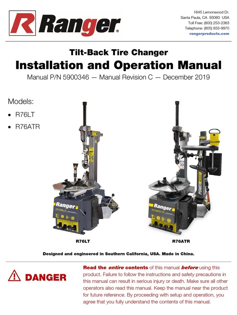
foc.us F640 User manual

F640
User’s manual
EN
The Manufacturer declines all liability for any damage to people or property caused by incorrect use of this product.
Subject to change without prior notice.

2 User’s manual - F640
Elaborazione graca e impaginazione
Ufcio Pubblicazioni Tecniche
All rights of total or partial translation, electronic storage,
reproduction and adaptation by any means (including
microlm and photocopies) are reserved.
The information in this manual is subject to variation without
notice.
English

User’s manual - F640 3
ORIGINAL INSTRUCTIONS
CONTENTS
INTRODUCTION .............................................................................................4
TRANSPORT, STORAGE AND HANDLING ...................................................5
UNPACKING/ASSEMBLY ............................................................................... 6
HOISTING/HANDLING ....................................................................................6
INSTALLATION ...............................................................................................6
ELECTRICAL AND PNEUMATIC CONNECTIONS .........................................7
SAFETY REGULATIONS ................................................................................ 9
DESCRIPTION ..............................................................................................10
MANUFACTURER’S LABEL .........................................................................10
TECHNICAL DATA ....................................................................................... 11
STANDARD ACCESSORIES ........................................................................12
ACCESSORIES SUPPLIED ON DEMAND ................................................... 12
SPECIFIED CONDITIONS OF USE .............................................................. 12
MAIN OPERATING PARTS ...........................................................................13
WARNING SIGNALS .....................................................................................16
PRACTICAL HINTS .......................................................................................16
USE ............................................................................................................... 17
DEMONTAGE ................................................................................................ 19
MONTAGE ..................................................................................................... 20
INFLATION .................................................................................................... 21
MAINTENANCE ............................................................................................23
ENVIRONMENTAL INFORMATION ..............................................................24
INFORMATION AND WARNINGS ABOUT OIL .............................................26
RECOMMENDED FIRE-EXTINGUISHING DEVICES .................................. 26
GLOSSARY ...................................................................................................27
TROUBLE SHOOTING ................................................................................. 27
ELECTRICAL SYSTEM DIAGRAM ...............................................................29
PNEUMATIC SYSTEM DIAGRAM ................................................................ 32

4 User’s manual - F640
INTRODUCTION
The purpose of this manual is to furnish the owner and operator with a set of practical, safe instruc-
tions on the use and maintenance of the tyre changer.
Follow all the instructions carefully and the machine will give you the efcient and long-lasting service
that has always characterized products, making your work considerably easier.
The following points dene the levels of danger regarding the machine, associated with the warning
captions found in this manual:
DANGER
Refers to immediate danger with the risk of serious injury or even death.
WARNING
Dangers or unsafe procedures that can cause serious injury or even death.
CAUTION
Dangers or unsafe procedures that can cause minor injuries or damage to property.
Read these instructions carefully before powering up the machine. Keep this manual and all illustrative
material supplied with the machine in a folder near the tyre changer where it is readily accessible for
consultation by the machine operators.
The technical documentation supplied is considered an integral part of the machine; and must always
accompany the equipment if it is sold or transferred to a new owner.
The manual is only to be considered valid for the model with the serial number indicated on the
nameplate applied to it.
WARNING
Observe the contents of this manual: the producer declines all liability in the case of uses of
the machine not specically described and authorized in this manual.
WARNING
This machine must be used only by qualied and authorized personnel. A qualied operator
is construed as a person who has read and understood the tyre changer manufacturer’s
instructions as well as the tyres and wheel rims manufacturers’, is suitably trained, and is
conversant with safety and adjustment procedures to be adhered to during operations. Use
of the machine by unskilled staff may constitute a serious risk for the operator and for the
nal user of the product processed (the wheel rim and tyre assembly).
NB:
Some of the illustrations in this manual have been taken from photographs of prototypes: standard
production machines may vary in some respects.
These instructions are intended for people with basic mechanical skills. We have therefore omitted
detailed descriptions of procedures such as how to loosen or tighten the xing devices on the ma-
chine. Do not attempt to perform operations unless properly qualied and with suitable experience.
In case of need, contact an authorized Service Centre for assistance.

User’s manual - F640 5
TRANSPORT, STORAGE AND HANDLING
Conditions for transporting the machine
The tyre changer must be transported in its original packing and stowed in the position shown on
the external packing.
- Packing dimensions:
• width ................................................................................................................................950 mm
• depth ............................................................................................................................. 1150 mm
• height .............................................................................................................................1080 mm
- Weight of the machine with packing:
• standard .............................................................................................................................. 286kg
Ambient conditions for machine transport and storage
Temperature: -25° ÷ +55°C.
WARNING
Do not stack other goods on top of the packing to avoid damaging it.
Handling
To move the packing, insert the tines of a fork-lift truck into the slots on the base of the packing itself
(pallet) (g. 1).
ATTENTION
Carry out the moving operations with great care, paying attention to move the packaged machine
only from the side clearly indicated on the packaging.
Failure to follow these recommendations may result in damage to the machine and put the operator’s
safety at risk.
Before moving the machine, refer to the HOISTING/HANDLING section.
1
1a
53
6
2

6 User’s manual - F640
UNPACKING/ASSEMBLY
WARNING
Take utmost care when unpacking, assembling, hoisting and installing the machine as described
in this heading.
Keep the original packing in good conditions to be used if the equipment has to be shipped in the
future and make sure that the machine has not suffered damage in transit.
Failure to comply with these instruction may damage the machine and risk the operator’s safety.
Remove the upper part of the packing.
The machine is fully assembled, comprising 2 main groups: 2- tyre changer, 3- accessories.
Identify the points 5, 6 and 7 at which the machine is anchored to the pallet and proceed to remove
xing devices ( g. 1a ).
HOISTING/HANDLING
To remove the machine from the pallet :
Lift the machine sideways enough to insert the forks of the fork-lift truck between the machine and
the pallet as showed in g.2.
At this point is possible to release the working arm removing the cord which binds the arm to the
turntable.This hoisting point must be used whenever you need to change the installation position of
the machine. Do not attempt to move the machine until it has been disconnected from the electricity
and compressed air supply systems.
INSTALLATION CLEARANCES
WARNING
The installation site must be chosen in strict compliance with the relevant regulations regarding
Safety in the workplace.
IMPORTANT: for correct, safe use of the equipment, users must ensure a lighting level of at least
300 lux in the place of use.
2
3
800
800
700

User’s manual - F640 7
CAUTION
The installation of the machine must be performed in a dry area which must be protected
from adverse weather conditions.
Install the tyre changer in the chosen work position, complying with the minimum clearances shown
in g. 3, adjust the height of the bead breaking support foot so that the machine is correctly posi-
tioned on the ooring.
Place the machine so that the plug-socket combination is easily accessible.
The machine must be placed on a horizontal surface, preferably concrete or tiled oor. Do not install
on unstable or damaged surfaces.
The surface on which the machine rests must withstand the loads transmitted during operation. The
surface must have a load-carrying capacity of at least 500 kg/m2.
Ambient working conditions
- Relative humidity 50% (temp. 40°C) ÷ 90% (temp. 20°C) without condensation.
- Temperature 5°C ÷ 40°C.
WARNING
Use of the machine in a potentially explosive atmosphere is not permitted.
ELECTRICAL AND PNEUMATIC CONNECTIONS
WARNING
All operations required for the electrical connections of the equipment must be carried out
exclusively by a qualied electrician.
Before connecting the air supply system, make sure the machine is set up as in g. 4:
pedal 3 and 4 totally downwards, column forward.
- The electrical supply must be suitably sized in relation to:
• the machine input power as specied in the corresponding machine data plate;
A
B
4
3
4
5

8 User’s manual - F640
• the distance between the machine and the power supply hook-up point, so that voltage drops
under full load do not exceed 4% (10% during start-up) compared with the rated voltage speci ed
on the data plate.
- The operator must:
• t a power plug on the power supply lead in compliance with the relevant safety standards (A g 5);
• Connect the machine to an ef cient grounding circuit in compliance with the relevant electric stan-
dards, provided with a circuit breaker (residual current set to 30mA);
• t fuses to protect the power supply line, rated as indicated on the general wiring diagram in this
manual.
- In order to prevent the machine from being used by unauthorized personnel, it is advisable to
disconnect the power supply plug when the machine remains idle (switched off) for long periods.
WARNING
A good grounding connection is essential for correct operation of the machine.
NEVER connect the earth wire to a gas or water pipe, telephone line or any other unsuitable
objects.
Check that the pressure and ow-rate provided by the compressed air system are compatible with
those required for proper operation of the machine - see “Technical Data” section. For correct machine
operation the compressed air supply line must provide a pressure range from no less than 8 bar to
no more than 16 bar.
Connect the compressed air system by means of a supply pipe connected to the intake of the air
treatment unit on the REAR SIDE of the machine base.
Check that there is air lubrication oil in the Lubricating unit; re ll if there is little or no oil. Use SAE20 oil.
The customer must provide an air cut-off valve upstream of the air treatment and regulating device
supplied with the machine.
WARNING
Connection 1 should be considered as an emergency valve to disconnect the machine from
the air line ( g.6)
1
6

User’s manual - F640 9
SAFETY REGULATIONS
The equipment is intended for professional use only.
WARNING
Only one operator may work on the equipment at a time.
WARNING
Failure to comply with the instructions and danger warnings may seriously injure operators
and any other person present near the machine. Do not operate the machine until you have
read and understood all the danger, warning and caution notices in this manual.
This machine must be used only by qualied and authorized personnel. A qualied operator is construed
as a person who has read and understood the manufacturer’s instructions, is suitably trained, and
is conversant with safety and adjustment procedures to be adhered to during operations. Operators
must not use the machine under the inuence of alcohol or drugs which may affect their capacity.
The operator must, in all cases:
- Be able to read and understand all the information in this manual.
- Have a thorough knowledge of the capabilities of this machine.
- Keep unauthorized persons well clear of the area of operation.
- Make sure the machine has been installed in compliance with all relevant regulations and legislation.
- Make sure that all machine operators are suitably trained, that they are capable of using the
equipment correctly and that they are adequately supervised.
- Never leave nuts, bolts, tools or any other equipment on the tyre changer as they may become
entrapped between moving parts.
- Not touch power lines or the inside of electric motors or any other electrical equipment before
making sure the power supply has been disconnected.
- Read this manual carefully and learn how to use the machine correctly and safely.
- Always keep this user and maintenance manual in an easily accessible place and consult it
whenever necessary.
WARNING
Do not remove or deface the Danger, Warning or Instruction decals. Replace any missing or
illegible decals. If one or more decals have been detached or damaged, replacements can be
obtained from your nearest dealer.
- When using and servicing the machine, observe the standardized industrial accident
prevention regulations for high voltages.
- Any unauthorized alterations or changes made to the machine shall automatically release the
manufacturer from any liability for damage or accidents attributable to such modications.
Specically,tampering with or removing the safety devices is a breach of the regulations for Safety
in the workplace.
- User must wear personal protective equipment such as gloves, safety footwear and goggles.
WARNING
When operating or servicing the equipment, tie back long hair and do not wear loose-tting clothes,
ties, necklaces, rings or wristwatches which could become entrapped by moving parts.

10 User’s manual - F640
DESCRIPTION
The machine is a electro-pneumatic tyre changer automatic, to be used with wheels with drop
centre featuring weights and dimensions as described in the technical data section.
It is designed to work effectively on:
- Conventional wheels;
- Reverse rim wheels or wheels without central hole (use optional kit);
- Run-at tyres with reinforced sidewalls*.
* WARNING: There are specically studied procedures for this type of wheels.
NB: It may be difcult and sometimes impossible to clamp and/or demount wheels of Vintage
cars (cars out of production for over 30 years), some types of rally wheels and non-standardized
street wheels.
The machine is solidly constructed. It operates with the wheel in a vertical position for bead breaking
and horizontal for mounting and demounting tyres. All machine movements are controlled by the
operator by means of the pedals.
MANUFACTURER’S LABEL
Each machine carries a plate with its identication and some technical data.
As well as the manufacturer’s details, it indicates:
Mod. - Machine model;
V - power supply voltage in Volts;
A - Input voltage in Amperes;
kW - Absorbed power in kW;
Hz - Frequency in Hz;
Ph - Number of phases;
Bar - Operating pressure in Bar;
Serial No. - Machine serial number;
EC - EC marking.
Mod.
Ser. N.
Volt
Kw
Amp.
Year
Weight
Ph
Hz
Bar
Automotive Equipment
TECO s.r.l. Via Pio La Torre 10
42015 Correggio (R.E.) - ITALY
tel. 0522/631562 - fax 0522/642373
WARNING
It is forbidden to modify or remove the data in the plate.

User’s manual - F640 11
TECHNICAL DATA
- Overall dimensions (see g. 7):
• Length ........................................................................................................... 1200 min 1730 max
• Width .............................................................................................................. 920 min 1250 max
• Height ........................................................................................................... 1650 min 1940 max
- Table top clamping capacity:
• inside clamping .................................................................................................................. 13”-25”
• outside clamping ................................................................................................................. 10”-22”
- Rim width: ............................................................................................................................370 mm
- Maximum tyre diameter: ....................................................................................................1060 mm
- Bead breaking pressure: ................................................................................................... .2900 Kg
- Air pressure ........................................................................................................................8-10 Bar
- Motor electrical features:
• 1ph version - 1 speed 220V - 50Hz .................................................................6A - 0,75 kW
• 3ph version - 1 speed 230V - 50Hz .............................................................2,8A - 0,55 kW
• 3ph version - 1 speed 400V - 50Hz .............................................................1,6A - 0,55 kW
• 3ph version - 2 speed 230V - 50Hz ...................................................5,3/6,8A - 0,8/1,1 kW
• 3ph version - 2 speed 400V - 50Hz ...................................................2,8/4,4A - 1,1/1,5 kW
- Weight ..................................................................................................................................255 kg
- Weight of electrical/ electronic components: ........................................................................ 11,5 kg
- Noise level
• A-weighted sound pressure level (LpA) at the working position .......................... < 70 dB (A)±3dB(A)
The noise levels indicated correspond to emission levels and do not necessarily represent safe
operating levels. Although there is a relationship between emission levels and exposure levels, thi-
scan not be used reliably to establish whether or not further precautions are necessary. The factors
which determine the level of exposure to which the operator is subject to include the duration of the
exposure, the characteristics of the workplace, other sources of noise, etc. The permitted exposure
levels may also vary according to the country. However, this information will enable machine users
to make a more accurate assessment of hazard and risks.
7
Min 920 - Max 1250
Min 1650 - Max 1940
Min 1200 - Max 1730

12 User’s manual - F640
STANDARD ACCESSORIES
937200003.........................................................................................................................Tyre lever
937200004.......................................................................................................................Brush (BR)
ACCESSORIES ON DEMAND
939005100........................................................................................................................... UWA 24
(Adapters to increase the turntable clamping capacity (to be used in combination with US TPH)
939005101................................................................................................................................ UMA
Universal motorcycle adapters
939005106.................................................................................................................................CRA
Adapters for convex rims
939005201.............................................................................................................................. PLS 2
(Pneumatic wheel lift complete with roller rest)
SPECIFIED CONDITIONS OF USE
The tyre changers has been designed exclusively for mounting and demounting tyres, using the tools
the machines are equipped with, following the instructions in this manual.
WARNING
Any other operation carried out on the machine is considered as improper use and shall be
construed as negligence.
These machines are equipped with an ination system independent from any other function described
above. Take great care when using it (read the INFLATION chapter).
WARNING
You are strongly advised not to use equipment or
tools not originally manufactured by us.
Figure 8 shows the positions assumed by the operator
during the various stages of work with the machine.
A Bead breaker
B Tyre demounting and mounting
C Ination area.
WARNING
Keep hands well away from machine moving
parts.
WARNING
To stop the machine in an emergency:
- disconnect the power supply plug;
- isolate the compressed air supply network by disconnecting the (quick-coupling) shut-off valve (g. 6).
8
C
B
A

User’s manual - F640 13
MAIN OPERATING PARTS
WARNING
Get to know your machine: the best way to prevent accidents and obtain top performance is to get
to know exactly how it works. Learn the function and location of all the controls. Check carefully that
each of the controls operates properly. To avoid any risk of accidents and injuries, the machine must
be installed and operated correctly and serviced regularly.
The machine main operating parts are shown in g. 9:
1 Bead breaker pedal
2 Turntable rotation, 4 position-pedal:
• released position = turntable still
• pedal pressed down = rotation clockwise
• pedal pressed deep down = rotation clockwise double-speed
• pedal pulled up = rotation anti-clockwise
3 Clamp control pedal (to open and close the clamps)
4 Vertical post control pedal
5 Turntable
6 Clamp
7 Mounting/demounting tool
8 Working arm
9 Working arm cylinder ( Pneumatic version)
10 Vertical post
11 Filter Regulator + Lubricator Unit (regulates pressure, lters, removes humidity of and lubricates
the compressed air supplied)
12 Wheel support
13 Bead breaker blade
14 Tyre lever
21 Locking button:
A) working arm ascent; B) working arm descent; C) locked

14 User’s manual - F640
9
A
B
C
21
21
22
9
12
3
4
5
6
7
8
10
11
12
13
14

User’s manual - F640 15
WARNING SIGNALS
PAY THE UTMOST ATTENTION TO THE WARNING LABELS ATTACHED TO THE MACHINE.
USING THE MACHINE WITHOUT READING THE WARNING SIGNALS MAY BE
SERIOUSLY DANGEROUS FOR THE OPERATOR.
DANGER OF CRUSHING PARTS OF THE
BODY BETWEEN THE BEAD BREAKER AND
THE MACHINE
C
DANGER OF HAND CRUSHING
BETWEEN CLAMP AND RIM.
DANGER OF HAND CRUSHING
BETWEEN MOUNTING HEAD
AND WHEEL.
D
CAUTION: AIR BLAST.
MAX. AIR SUPPLY LINE
PRESSURE 16 BAR
E
INFLATING GUN CONNECTION.
DO NOT DIRECTLY CONNECT
THE COMPRESSOR.
(only on standard version)
CAUTION: ELECTRIC CURRENT
DANGER OF CRUSHING PARTS OF THE
BODY BETWEEN THE BEAD BREAKER AND THE
WHEEL.
DANGER OF CRUSHING PARTS OF THE
BODY BETWEEN THE BEAD BREAKER ARM
AND THE MACHINE.
A
CAUTION: TOWER TILTING
000103700
000103500
000103000
000103100
000102800
F
000102700
G
000103600
H
I
J
000103400
000103200
000103300
B
D
G
B
H
I
J
F-E
A
C

16 User’s manual - F640
Preliminary checks
Check that there is a pressure of at least 8 bar on the pressure gauge of the Filter Regulator +
Lubricator unit.
Check that the machine has been adequately connected to the power mains.
Deciding from which side of the wheel the tyre must be demounted
See g. 10.
Find the position of the drop centre A on the wheel rim. Find the largest width B and the smallest width C.
The tyre must be demounted or mounted with the wheel positioned on the turntable with the side
with the smallest width C facing upward.
Special instructions
Some types of wheels on the market require special procedures and precautions which differ from
the standard procedure.
This applies in particular to the following types of wheels:
Alloy rim wheels: some wheels have alloy rims where the drop centre A is very small or non-existent -
g. 10-B. These rims are not approved by the DOT (Department of Transportation) standards - these
initials certify that tyres comply with the safety standards adopted by the United States and Canada
(these wheels cannot be sold in these markets).
DANGER
Take utmost caution when mounting the tyre. The rim and/or the tyre may be damaged
accidentally, with the risk of the tyre exploding during the ination stage.
European style high-performance wheels (asymmetric curvature) - g.10-C: some European
wheels have rims with very pronounced curvature C, except in the area of the valve hole A where the
curvature is less pronounced B. On these wheels the bead must rst be broken in correspondence
with the valve hole, on both the top and bottom sides of the wheel.
Wheels with low pressure indicator system - g.10-D.
CC
A
B
AB
A
CC
A
B
D
C
A
B
10

User’s manual - F640 17
USE
BEAD BREAKING
The bead breaker arm of the machine is equipped with a patented system which allows
to obtain two different working inclinations between the blade and the wheel.
-Fully close the turntable clamps (fig. 11) acting on pedal 3 fig. 9.
-Remove the weights from the rim.
-Fully deate the tyre, removing the valve
- Adjust the rim rest depending on wheel diameter
-Adjust the inclination of the blade according to the wheel width by means of the pin in order to
obtain a better inclination between the blade and the tyre: in position 1 in g.12 for low width tyres,
in position 2 for high width tyres
-Place the wheel as shown in g. 13 and take the blade near the bead, keeping the necessary safety
distance between the rim and the bead breaker blade, so that the latter works on the tyre and not
on the rim.
-Press pedal 1 (g 9) to activate the bead breaker and free the bead from the rim.
Release the pedal. Pressing the bead breaker pedal (1 g. 9) the arm moves (13 g.9) and it may
be dangerous (crushing danger); pay the utmost attention during bead breaking.
Repeat this operation on the other side of the wheel.
It may be necessary to break the bead at several points to free it completely.
WHEEL CLAMPING
-Check if there are any weights left on the rim; if so, remove them.
-Thoroughly lubricate the sides of the tyre around the entire circumference of the lower and upper
bead to facilitate the demounting and avoid damaging the beads (g.15).
-Make sure that nobody is behind the tyre changer and tilt the tower backwards keeping the locking
button in “locked” position.
-Depending on the diameter of the rim, close the four clamps if the rim is to be clamped from inside
or open them if the rim is to be clamped from outside. Place the wheel on the turntable, push it lightly
down and act on the control pedal to lock the wheel in its proper position (g. 15).
11
12
1
2
A
A

18 User’s manual - F640
Acting on the turntable pedal (3 g.9) closes the clamps and may be dangerous (danger of hand
crushing). During rim clamping, do not keep the hands under the tyre.
• Tool positioning (P version - g.16)
- Press the pedal 4 to move the column into its working position. Press the locking button into po-
sition A to contemporarily unlock working arm and horizontal arm. The tool will move upwards in
its rest position.
With the locking button in position B, the tool can move freely downwards up to the rim edge or up to
the minimum working height. Press the locking button in position C to contemporarily lock vertical
and horizontal arms. In this case the tool will be automatically positioned at a security distance
from the rim edge.
- Make the head go down on the rim (push button 18).
15
16
A
B
C
13
14

User’s manual - F640 19
- For correct tool positioning, the insert (g. 19) must be at the end position with the rim edge, where
the vertical wall begins.
ATTENTION : Use the handle to achieve the correct tool positioning on the rim.
- Press the block 14 to x the tool position.
The distance between rim and tool head will remain unchanged till the control button is in locking
position.The operator can tilt the vertical post (i.e. when handling a set of tyres having same di-
mensions) without repositioning the tool on the rim.
ATTENTION : Risk of hand crushing between demounting / mounting tool and the wheel.
DEMOUNTING
• Upper bead demounting (g.20)
- Move the working arm in work position, and lift the bead above the forward portion of the mounting
head itself.
- Make sure that the tyre has not beaded in on the operator’s side. If necessary, use a bead clamp
and/or the bead pressing device.
- Make the turntable rotate clockwise by pressing the relevant pedal (2 g.9) lightly and
repeatedly, then keep the pedal continuously pressed.
- Rotate the wheel through one turn and at the same time press down with a hand on the side of
the tyre opposite to the mounting head, in order to position the bead in the central groove of the rim.
17
18
4
19

20 User’s manual - F640
• Lower bead demounting (g. 21)
- Lift the tyre nearby the tool.
- Use the tyre lever and hook the lower tyre bead.
- Acting on pedal 1, make the wheel turning till the complete demounting of the tyre from the rim
• Demounting complete
- At the end of the demounting activity, tilt the post using the on-purpose pedal (4 g.9) and, then,
remove the tyre.
MOUNTING
CAUTION
Always check that the tyre/rim combination is correct in terms of compatibility (tubeless tyre on
tubeless rim; tube type tyre on tube type rim) and geometrical size (keying diameter, cross-section
width, Off-Set and shoulder prole) before mounting.
Also check that rims are not deformed, that their xing holes have not become oval, that they are
not scaled or rusty and that they do not have sharp burrs on the valve holes.
Check that the tyre is in good condition with no signs of damage.
• Tyre preparation (g. 22)
- Grease both the tyre beads.
- Place the tyre on the rim
• Head positioning
- Operate pedal (4) to move the head into its working position.
NB: The tool is already in the correct position for mounting the tyre, unless the type of rim
has been changed.
• Lower bead mounting
- Place the bottom bead of the tyre underneath the tool and at the same time apply a little pressure
to
the tyre by hand while starting to rotate the wheel (pedal 1) for easier bead insertion.
- Rotate until tyre mounting is complete.
20
21
Table of contents
Popular Tyre Changer manuals by other brands

Aston Global
Aston Global ATC-5733 Installation, Operation and Maintenance User’s Manual

Coats
Coats CHD-9041 Operating and maintenance instructions

ATH-Heinl
ATH-Heinl M126 operating instructions

Fasep
Fasep BALATRON B433.G3 user manual

Corghi
Corghi HD 900 Operator's manual

Corghi
Corghi 4-113212B Operator's manual