BV BV-BF-04 Guide

bathroom VENTILAtion fan
INSTALLatiON MANUAL and USER GUIDE
MODEL: BV-BF-04

CONTENTS
General Safety Information and Warnings .............................................................................
Included Parts and Accessories ...................................................................................................
Additional Tools/Supplies Required for Installation ...........................................................
Planning Installation ........................................................................................................................
Specications .....................................................................................................................................
Dimensions ..........................................................................................................................................
Wiring Diagram .................................................................................................................................
Fan Housing Installation (Direct Joist or Suspension Bracket Joist Mounting) ........
Cleaning The Ventilation Fan .......................................................................................................
2
4
4
5
6
6
6
8
10

GENERAL SAFETY INFORMATION AND WARNINGS
For your safety and to ensure proper performance of the unit, it is very important to read these instructions carefully
before installation. Failure to comply with the instructions contained herein could result in personal injury or property
damage. We recommend that you keep this booklet for future reference. All units should be installed by a licensed
electrician.
READ and SAVE THESE INSTRUCTIONS
This commercial series bathroom fan uses state-of-the-art technology providing superior, long-life performance
for your room ventilation needs.
General safety information and warning
WARNING
2
WARNING – “TO REDUCE THE RISK OF FIRE, ELECTRIC SHOCK, OR INJURY TO PERSONS, OBSERVE THE FOLLOWING:”
Use this unit in the manner intended by the manufacturer. If you have any questions, contact the manufacturer.
Before servicing or cleaning unit, switch power off at service panel and lock the service disconnecting means to -
prevent power from being switched on accidentally. When the service disconnecting means cannot be locked,
securely fasten a prominent warning device, such as a tag, to the service panel.
?"For General Ventilating Use Only. Do Not Use To Exhaust Hazardous Or Explosive Materials And Vapors."
Electrical service supply must be 120V 60Hz.
Wires from the house power supply to the unit should not be smaller than size 14 AWG.
Follow all local safety and electrical codes, as well as requirements for NEC (National Electrical Code) and OSHA
(Occupational Safety and Health Act).
This unit must be properly grounded.
This unit is equipped with a built-in thermal cut-off for safety and to prolong the life of the motor.
Always disconnect the power supply prior to servicing the fan, motor or junction box. Do not bend power wires.
Do not install where the air temperature will exceed 40° C (104°F).
This ventilating fan is approved for use over a bathtub or shower when installed in a GFCI-protected circuit.
Do not install in a cooking area.
Exercise care not to damage existing wiring when cutting or drilling into walls or ceilings.
Do not use this fan with any solid-state control device.
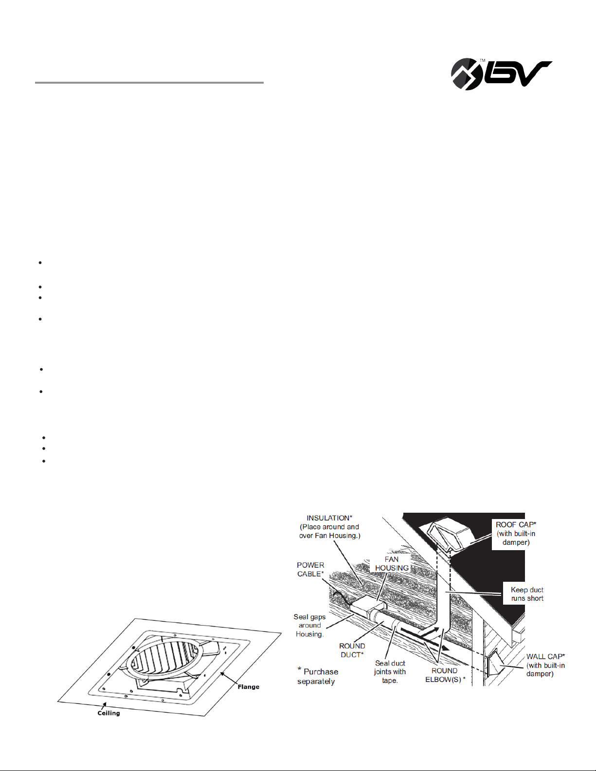
Ductwork should be installed in as straight a line as possible, with minimum bends.
Ductwork size must be a minimum of the discharge and should not be reduced.
The fan is intended to be mounted at least 7 feet (2.1m) above the oor.
Do not kink or excessively bend the electrical wires.
protect the electrical wires from sharp edges, oil, grease, hot surfaces, chemicals, or other objects.
Do not install the unit where ducts where the airflow can be severely restricted.
There should always be an adequate air supply to the vented area.
The control device should not be installed within reach of the bathtub or shower.
Suitable for ceiling installation over tub or shower.
?WARNING - TO REDUCE THE RISK OF FIRE, ELECTRIC SHOCK, OR INJURY TO PERSONS, OBSERVE THE FOLLOWING:?
Installation work and electrical wiring must be done by qualified person(s) in accordance with all applicable codes
and standards, including fire-rated construction
Sufficient air is needed for proper combustion and exhausting of gases through the flue (chimney) of fuel burning
equipment to prevent back drafting. Follow the heating equipment manufacturer's guideline and safety standards
such as those published by the National Fire Protection Association (NFPA), and the American Society for Heating,
Refrigeration and Air Conditioning Engineers (ASHRAE), and the local code authorities.
When cutting or drilling into wall or ceiling, do not damage electrical wiring and other hidden utilities.

3
General safety information and warning
Ducted fans must always be vented to the outdoors.
If this unit is to be installed over a tub or shower, it must be marked as appropriate for the application
and be connected to a GFCI (Ground Fault Circuit Interrupter) - protected branch circuit.?
The ceiling shall only be installed if the insulation is greater than the value specified in section 6.4.9.
All wiring must be in accordance with the National Electrical Cord, ANSI/NFPA 70- and local electrical codes.
Electrical installation should be performed by a qualified, licensed electrician.
1999
Do not use this fan unit with any solid-state speed control device.
If this unit is to be installed over a tub or shower, it must be marked as a appropriate for the application.
When the fan is going to install in the bathroom, the fan and the tub need to be more than 1.0 meter between
between each other, the fan required to install at the other side of the tub in ceiling. Acceptable for use over a
bathtub or shower when installed in a GFCI protected branch circuit.

INCLUDED PARTS And accessories
4
LIST OF ADDITIONAL TOOLS/SUPPLIES REQUIRED FOR INSTALLATION
12” Suspension bracket
6” Suspension bracket
14” Suspension bracket
Part Name/Photo
Part # Qty
Part Name/Photo
Part # Qty
1
2
M4*30
M4*12
M4*10
5
6
7
Bath fan housing
Bath fan grille
1
1
8
2
1
1
1
1
Safety glasses
6-in. round duct, elbows if needed, installation tools and other supplies including
foil duct tape or 6-in. clamp tosecure to fan housing
Switch to operate fan
Phillips screwdriver
Tape measure
Utility knife or saw for cutting drywall
Wire cutter/stripper
Wire nuts
Ladder
ADDITIONAL TOOL/SUPPLIES

PLANNING INSTALLation
5
When installing the ventilation fan in a new construction site, install the main body of the fan and ductwork during the
rough-in construction of the building. The grille should be installed after the nished ceiling is in place. Use the
dimensions provided in this manual to determine the required hole size for the ceiling.
The ducting from this fan to the outside of the building has a strong effect on the airow, noise and energyuse of the
fan. Use the shortest, straightest duct routing possible for best performance and avoid installing the fan with smaller
ducts than specied in this manual. Insulation around the ducts can reduce energy loss and inhibit mold growth. Fans
installed with existing ducts may not achieve their rated airow. Do not install the ventilation fan in areas where the
ductwork will require congurations as shown in Fig. 1 below.
Recommended installation includes insulating around ductwork and the fan housing to minimize heat loss (see
Fig. 2 above). Seal all gaps around the housing with caulk or other similar material to inhibit air leakage to the
exterior of the thermal envelope of the building. Rigid sheet metal duct and the shortest path to the outside
will minimize static pressure losses and promote adequate air ow.

specifications
6
Model No.
BV-BF-04
Air CFM
200CFM
V
120
Hz
60
Duct Diameter
6 in. (15.25 cm)
Noise (Sones)
2.0
DIMENSIONS
Ceiling
Opening - D
8 5/16 in.
(21 cm)
Ceiling
Opening - W x L
10 7/16 in.x10 7/16 in
(26.5cm x 26.5 cm)
Housing
Dimension – W x L
10 5/16 in.x10 5/16 in
(26.2 cm x 26.2 cm)
Housing
Dimension - D
8 in.
(20.32 cm)
Ceiling
Opening - W x L
12 11/16 in.x12 11/16 in
(32.2 cm)
WIring diagram

Fan housing installation
7
FAN HOUSING INSTALLATION (DIRECT JOIST MOUNTING OR SUSPENSION BRACKET JOIST MOUNTING)
Check the area above installation location to be sure that:
a. Ductwork can be run and there is sufcient area for proper ventilation;
b. Wiring can be run to the planned location (wires from the power supply to the unit should not be smaller than
size 14 AWG);
c. There will be access to ductwork and wiring for inspection and future maintenance; and
d. No wiring or other obstructions will interfere with installation.
For installation in existing construction:
Installing the fan housing in an existing building requires access (attic or crawl space) in the planned installation
location above the existing ductwork and wiring.
Inspect existing ductwork and wiring before proceeding with installation.
Step 1:
Select the location for your fan in the ceiling.
For optimal performance, plan for the shortest
possible duct with the fewest elbows.
When positioning fan housing for installation, ange of
housing trim ring must be level with the outside of the
drywall and visible from the room below.
Installation I (Joist Mounting)
CAUTION
Mount junction box cover very carefully so that lead wires are not pinched.
WARNING
Disconnect power source before working on unit.
When making wiring connections always take care to prevent excessive slack in the wiring since a large of current
is drawn through the electrical wire.
Connect the switch to the live (block color) side.
The cord connect by the plastic connector and protected by cables , the plastic connector and the cables are
provided by the clients.
1. Check area above planned location to be sure that:
CAUTION
Duct work can be installed and that area has sufficient ventilation
Wiring can be run to the area of the planned location
Ensure that no wiring or other obstructions will interfere with installation.
2. Plan a suitable location for ventilating fan.(next to ceiling joist)
3. Before installation, provide inspection and maintenance access to the location that will not interfere with installation
work as per INSTALLTION 1.

Fan housing installation
8
Step 2:
Direct Joist-Mount: Slide suspension brackets (Part
#5 (back) and Part #6 (front)) into slots in fan
housing. Using wood screws (Part #3), secure
housing ange to joist, then secure suspension
brackets to joist on other side. If spacing between
joists is greater than 16”, use extension bracket (Part
#7, see diagram right).
Suspension Bracket-Mount: Slide suspension
brackets (Part #5 (back) and Part #6 (front)) into
slots in fan housing. Using wood screws (Part #3),
secure suspension brackets to joists. If spacing
between joists is greater than 16”, use extension
bracket (Part #7, see diagram right).

fan housing installation
Step 3:
To secure brackets to fan housing, insert
machine screws (Part #4) in each. Tighten machine
screws to prevent housing vibration while fan is in
operation.
Step 7:
To attach the grille, pinch both mounting
springs on grille and insert ends into narrow
rectangular slots inside the fan housing next to the
fan motor.
Step 4:
Install a 6-in. circular duct and secure to
housing with foil duct tape or clamp.
Step 5:
Disconnect the power supply before
proceeding with Step 5. Run 120V 60Hz house
wiring (with ground) from wall switches to fan
location. Remove junction box cover and, using wire
nuts, connect house wires to unit wires. Refer to
Wiring Diagram on page 4.
GREEN WIRES are ground wires. Connect 2 green
wires from the unit to 1 house green wire by
the wire nut.
WHITE WIRES are neutral. White to white.
BLACK WIRES are hot. Black to black.
Step 6:
Finish ceiling. Flange of housing must be level
with bottom of joist, or no lower than the nished
ceiling.
9

CLEANING THE VENTILation fan
10
Cleaning the unit periodically is advisable since dust, molds, grease, and other dirt particles can
affect the conductivity of the air in the unit.
Clean the unit as follows:
1) Remove the plastic grille.
2) Wash the cover with lukewarm water and use mild detergent such as liquid soap (avoid
harsh detergent or boiling water).
3) Dry the grille with a cloth or kitchen towel.
4) Clean inside of unit with vacuum cleaner (fan housing should not come into contact with
harsh chemicals or liquids).
5) Put the grille back in place.
MAINTENANCE
Disconnect power source before working on the unit .Routine maintenance must be done manually.
CAUTION
1.Does not use petrol, benzene, paint thinner or any other such chemical for cleaning the ventilation fan.
2.Never allow water to enter motor.
3.Never immerse resin parts in water over 60° C (140°F).
4.A ceiling-insert fan, wall-insert fan, or ceiling-insert fan/light combination intends to be used over a bathtub
5.Detailed installation instructions with illustrations shall be provide with all ceiling-insert, wall-insert, and
or shower shall be marked where visible during installation with the following or equivalent: Acceptable for use
over a bathtub or shower when installed in a GFCI protected branch circuit.
ceiling-insert fan/light abominations intend for use over a bathtub or shower .The instructions shall also include
the wording from the marking specified in 4.
Table of contents
Other BV Fan manuals
Popular Fan manuals by other brands

Ruck Ventilatoren
Ruck Ventilatoren DHA Series Assembly instruction

Create
Create UPWIND SAIL user manual

Nordic
Nordic HVLS Series installation manual

Progress Lighting
Progress Lighting AirPro P250032 installation manual

TJERNLUND
TJERNLUND SS1C SIDESHOT (DISCONTINUED VERSION-PRE UC1 UNIVERSAL CONTROL) 8504040 REV 4... installation instructions

Kichler Lighting
Kichler Lighting Monarch II instruction manual

BASETech
BASETech BT-2345471 operating instructions

Exquisit
Exquisit VT 33056 we instruction manual

stori
stori Verse installation guide

Homemaker
Homemaker ND-468i user manual

Hunter
Hunter Auberville Owner's guide and installation manual

Zehnder Rittling
Zehnder Rittling Adaptive ZLE100TA installation instructions