BV BV-WF-01-LV User manual

BV-WF-01-LV WALL FAN
Installation Guide
WARNING
Please read these instructions carefully before installing, operating, or servicing the fan. Retain this guide for future reference.
1
SERVICE PARTS
1
2
4
5
6
12
3
3
3
8
9
7
11
1013
14
15
1. Grille
2. Sheet Metal Nut
3. Sheet Metal Screws
4. Motor Mounting Bracket
5. Motor
6. Blade
7. Wiring Box Cover
8. Green Ground Screw
9. Wiring Box
10. Housing
11. Receptacle
12. Spring
13. Adjustable Duct
14. Wall Cap
15. Aluminum Ring
TO REDUCE THE RISK OF FIRE, ELECTRIC
SHOCK, OR INJURY TO PERSONS, OBSERVE
THE FOLLOWING:
1. Use this unit only in the manner intended
by the manufacturer. If you have questions,
contact the manufacturer at the address or
telephone number listed in the warranty.
2. Before servicing or cleaning unit, switch
power o at service panel and lock the service
disconnecting means to prevent power from
being switched on accidentally. When the
service disconnecting means cannot be
locked, securely fasten a prominent warning
device, such as a tag, to the service panel.
3. Installation work and electrical wiring must be
done by a qualied person(s) in accordance
with all applicable codes and standards,
including re-rated construction codes and
standards.
4. Sucient air is needed for proper combustion
and exhausting of gases through the ue
(chimney) of fuel burning equipment to
prevent backdrafting. Follow the heating
equipment manufacturer’s guideline and
safety standards such as those published
by the National Fire Protection Association
(NFPA), and the American Society for
Heating, Refrigeration and Air Conditioning
Engineers (ASHRAE), and the local code
authorities.
5. When cutting or drilling into wall or ceiling, do
not damage electrical wiring and other hidden
utilities.
6. Ducted fans must always be vented to the
outdoors.
7. This unit must be grounded.
8. To reduce risk of re, use only metal ductwork.
9. The electric service supply voltage must be
120V 60HZ.
1. For general ventilating use only. Do not use
to exhaust hazardous or explosive materials
and vapors.
2. To avoid motor bearing damage and noisy
and/or unbalanced impellers, keep drywall
spray, construction dust, etc. o power unit.
3. Please read specication label on product for
further information and requirements.
4. Do not use in the bathroom.
5. To reduce the risk of injury, install fan at least
2.1m (7 feet) above the oor.
CAUTION USE AND CARE
WARNING: Switch o power at service panel and
lock service panel before cleaning or servicing
this fan.
TO CLEAN FAN ASSEMBLY:
Unplug motor from receptacle. Remove the motor
assembly by loosening the mounting screws and
rotating the motor assembly.
Gently vacuum motor assembly and inside of
housing.
METAL AND ELECTRICAL PARTS SHOULD
NEVER BE IMMERSED IN WATER.
PERIODCALLY CHECK THE OUTER LOUVER
FOR ACCUMULATED DUST, LINT, ETC.,
WHICH MAY INTERFERE WITH PROPER
LOUVER CLOSURE.
WARNING: DO NOT SPRAY WATER INTO
LOUVER—DAMAGE TO THE FAN COULD
OCCUR AND WATER COULD ENTER HOUSE.
There is no need to oil the motor on this fan.
WIRING DIAGRAM
AUTOMATIC TERMINAL SWITCH
FAN HOUSING JUNCTION BOX
TO 120V/60HZ
BLACK WIRE
WHITE WIRE
GREEN WIRE

2
Remove wiring box from fan:
Unplug motor, loosen screw and remove electrical
wiring box cover.
Push electrical wiring box into housing and lift out.
NOTE: For easier removal of wiring box, remove
the motor assembly. Loosen the mounting
screws and rotate the motor assembly.
WARNING: Switch power o before making
electrical connections.
Remove knockout on wiring box using at blade
screwdriver and pliers.
Attach power cable to electrical wiring box and
switch box using the proper connector for the type
of cable being used.
Make electrical connections. Connect black to
black, white to white, and bare or green wire to
box using green ground screw.
NOTE: Fan can be installed in outside walls
up to 10″ thick. Walls less than 6″ thick will not
use the adjustable duct. Choose a location with
no obstructions. Fan can be operated by a wall
switch or speed control (available separately).
WARNING: When cutting or drilling into wall, do
not cut existing electrical wiring.
CAUTION: Do not mount fan above cooking
surface.
CAUTION: Before cutting opening, make sure to
mark center of opening on two sides of wall.
Cut a 6-3/8″ diameter opening in the outside wall
If using the adjustable duct, cut a 6-3/8″ diameter
opening in the inside wall. If not, cut a 6-1/8″
diameter opening in the inside wall.
INSTALLATION
1
SWITCH OR SPEED CONTROL
FAN
2
MOTOR ASSEMBLY
WIRING BOX
3
ELECTRICAL CABLE
GREEN WIRE AND GROUND SCREW
INSIDE WIRING BOX

Fasten fan to inside wall with proper screws and
wall anchors.
3
(For walls 6″ to 10″ thick only—including inside
and outside wall coverings.)
Stretch the adjustable duct, slide it over the
housing and tape it in place (non-tapered end of
exible duct may need to be shortened to t).
Position fan housing in wall. Drill pilot holes
through center of slots in mounting ange.
4
6
5
TAPE HERE

7Reinstall electrical wiring box and cover.
Reinstall motor assembly (if previously removed).
Plug the fan motor into receptacle on wiring box
cover.
4
TAPE HERE
8
CAULK EDGES
9
(Complete this step only if adjustable duct is
used.)
From outside, slip adjustable duct into the
aluminum ring attached to the wall cap and tape
the joint.
Compress the excess duct back into the opening
by positioning the wall cap against the outside
wall.
Fasten wall cap to outside wall with screws and
caulk around the edges.

10 Spin grilles onto mounting screws until the grilles
are tight against the wall.
Turn on power and check for proper operation of
fan.
LIMITED WARRANTY
This is a quality product. It was made with care, and BV oers a limited one-year warranty against any manufacturing defects as long as it has been used
as directed. BV will replace any product showing such manufacturing defects. This warranty does not include labor costs for the installation or removal of
the fan. For warranty assistance, call: 866-721-3888
5
MOUNTING SCREW

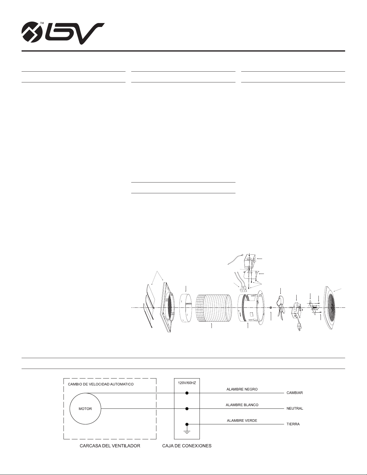
BV-WF-01-LV VENTILADOR DE PARED
Guía de Instalación
ADVERTENCIA
Porfavor, lea estas instrucciones detenidamente antes de instalar, operar o reparar el ventilador. Conserve esta guía para futura referencia.
6
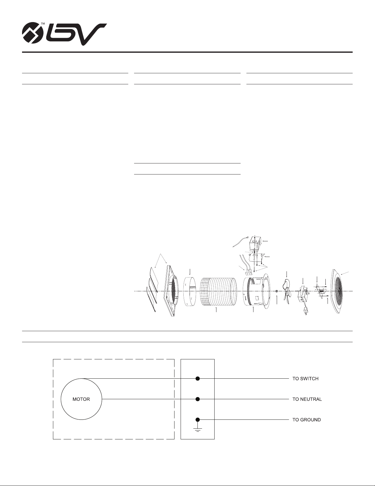
REPUESTOS Y MANTENIMIENTO
1
2
4
5
6
12
3
3
3
8
9
7
11
1013
14
15
1. Grille
2. Sheet Metal Nut
3. Sheet Metal Screws
4. Motor Mounting Bracket
5. Motor
6. Blade
7. Wiring Box Cover
8. Green Ground Screw
9. Wiring Box
10. Housing
11. Receptacle
12. Spring
13. Adjustable Duct
14. Wall Cap
15. Aluminum Ring
1. Solo para ventilación general. No lo use para
agotar materiales y vapores peligrosos o
explosivos.
2. Para evitar daños del motor y los impulsores
ruidosos y/o desequilibrados, mantenga
el rociador de paneles de yeso, polvo de
construcción, etc. fuera de la unidad de
potencia.
3. Lea la etiqueta de especicaciones del
producto para obtener más información y
requisitos.
4. No utilizar en el baño.
5. Para reducir el riesgo de lesiones, instale el
ventilador al menos a 2,1 m (7 pies) sobre
el piso.
PRECAUCIÓN USO Y CUIDADO
DIAGRAMA DE CABLEADO
PARA REDUCIR EL RIESGO DE INCENDIO,
DESCARGA ELÉCTRICA O LESIONES A LAS
PERSONAS, OBSERVE LO SIGUIENTE:
1. Utilice esta unidad solo de la manera
prevista por el fabricante. Si tiene preguntas,
comuníquese con el fabricante a la dirección
o número de teléfono que aparece listado en
la garantía.
2. Antes de reparar o limpiar la unidad, apague
el panel de servicio y bloquee los medios de
desconexión del servicio para evitar que la
fuente de poder se encienda accidentalmente.
Cuando los medios de desconexión del
servicio no puedan bloquearse, je de
forma segura un dispositivo de advertencia
prominente, como una etiqueta, al panel de
servicio.
3. El trabajo de instalación y el cableado
eléctrico deben ser realizados por personas
calicadas de acuerdo con todos los códigos y
estándares aplicables, incluidos los códigos y
estándares de construcción con clasicación
de resistencia al fuego.
4. Se necesita suciente aire para la combustión
adecuada y el escape de gases a través de
la chimenea del equipo de combustión para
evitar la extracción de aire. Siga las pautas
y las normas de seguridad del fabricante del
equipo de calefacción, como las publicadas
por la Asociación Nacional de Protección
contra Incendios (NFPA) y la Sociedad
Americana de Ingenieros de Calefacción,
Refrigeración y Aire Acondicionado
(ASHRAE), y las autoridades de código
locales.
5. Cuando corte o taladre en la pared o el
techo, no dañe el cableado eléctrico y otras
utilidades ocultas.
6. Los ventiladores canalizados siempre
deben ventilarse al aire libre.
7. Esta unidad debe estar conectada a tierra.
8. Para reducir el riesgo de incendio, use solo
conductos metálicos.
9. El voltaje de suministro del servicio
eléctrico debe ser de 120V 60HZ.
ADVERTENCIA: Apague la energia en el panel
de servicio y bloquee el panel de servicio antes
de limpiar o reparar este ventilador.
PARA LIMPIAR EL CONJUNTO DEL
VENTILADOR:
Desenchufe el motor del receptáculo. Retire
el conjunto del motor aojando los tornillos de
montaje y girando el conjunto del motor.
Aspire suavemente el conjunto del motor y el
interior de la carcasa.
LAS PIEZAS METÁLICAS Y ELÉCTRICAS
NUNCA DEBEN SUMERGIRSE EN AGUA.
CHEQUEAR PERIODICAMENTE LA
REJILLA EXTERIOR EN BUSCA DE POLVO
ACUMULADO, PELUSA, ETC; QUE PUEDAN
INTERFERIR CON EL CIERRE CORRECTO DE
LA REJILLA.
ADVERTENCIA: NO ROCÍE EL AGUA EN LA
REJILLA. EL DAÑO AL VENTILADOR PUEDE
OCURRIR Y EL AGUA PODRÍA ENTRAR A LA
CASA.
No es necesario engrasar el motor de este
ventilador.

7
Retire la caja de cableado del ventilador:
Desenchufe el motor, aoje el tornillo y retire la
cubierta de la caja de cableado eléctrico.
Empuje la caja de cableado eléctrico dentro del
alojamiento y extráigala.
NOTA: Para una extracción más fácil de la caja
de cableado, retire el conjunto del motor. Aoje
los tornillos de montaje y gire el conjunto del
motor.
ADVERTENCIA: Apague la energía antes de
hacer conexiones eléctricas.
Retire los oricios ciegos de la caja de cableado
con un destornillador de punta plana y unos
alicates.
Conecte el cable de energía a la caja de cableado
eléctrico y la caja de interruptores utilizando el
conector adecuado para el tipo de cable que se
utiliza.
Haz conexiones eléctricas. Conecte el cable
negro con negro, blanco con blanco y el verde a
la caja con un tornillo de tierra verde.
NOTA: El ventilador se puede instalar en paredes
exteriores de hasta 10 “de grosor. Las paredes de
menos de 6 ″ de grosor no utilizarán el conducto
ajustable. Elija un lugar sin obstrucciones. El
ventilador puede ser operado por un interruptor
de pared o control de velocidad (disponible por
separado).
ADVERTENCIA: Al cortar o taladrar en la pared,
no corte el cableado eléctrico existente.
PRECAUCIÓN: No monte el ventilador sobre la
supercie de cocina.
PRECAUCIÓN: Antes de cortar la abertura,
asegúrese de marcar el centro de la abertura en
los dos lados de la pared.
Corte una abertura de 6-3/8″ de diámetro en la
pared exterior.
Si usa el conducto ajustable, corte una abertura
de 6-3/8″ de diámetro en la pared interior. De
lo contrario, corte una abertura de 6-1/8″ de
diámetro en la pared interior.
INSTALACIÓN
3
1
INTERRUPTOR O CONTROL
DE VELOCIDAD
VENTILADOR
2
CONJUNTO DEL MOTOR
CAJA DE CABLEADO
CABLE ELÉCTRICO
ALAMBRE VERDE Y TORNILLO DE TIERRA
DENTRO DE LA CAJA DE CABLEADO

Sujete el ventilador a la pared interior con los
tornillos y anclas de pared adecuados.
8
(Solo para paredes de 6 ″ a 10 ″ de grosor,
incluidos los revestimientos de paredes interiores
y exteriores.)
Estire el conducto ajustable, deslícelo sobre el
alojamiento y péguelo con cinta adhesiva en su
lugar (es posible que sea necesario acortar el
extremo no cónico del conducto exible).
Coloque el alojamiento del ventilador en la pared.
Taladre agujeros piloto a través del centro de las
ranuras en la brida de montaje.
4
6
5
CINTA ADHESIVA AQUÍ

7Vuelva a instalar la caja de cableado eléctrico y
cobertor.
Vuelva a instalar el conjunto del motor (si se retiró
anteriormente).
Enchufe el motor del ventilador en el receptáculo
de la cubierta de la caja de cableado.
9
8
9
(Complete este paso solo si se utiliza un conducto
ajustable.)
Desde el exterior, deslice el conducto ajustable
dentro del anillo de amluminio unido a la tapa de
la pared y pegue con cinta adhesiva el conjunto.
Comprima el exceso del conducto de nuevo en la
abertura colocando la tapa de la pared contra la
pared exterior.
Sujete la tapa de la pared a la pared exterior con
tornillos y calafatee alrededor de los bordes.
CINTA ADHESIVA AQUÍ
CALAFATEE LOS BORDES

Gire las rejillas sobre los tornillos de montaje
hasta que las rejillas estén apretadas contra la
pared.
Encienda la energía y verique el funcionamiento
del ventilador.
GARANTÍA LIMITADA
Este es un producto de calidad. Fue hecho con cuidado, y BV ofrece una garantía limitada de un año contra cualquier defecto de fabricación, siempre
que se haya utilizado según las instrucciones. BV reemplazará cualquier producto que muestre tales defectos de fabricación. Esta garantía no incluye los
costos de mano de obra para la instalación o extracción del ventilador. Para asistencia con la garantía, llame al: 866-721-3888
10
10
TORNILLO DE FIJACIÓN
Table of contents
Languages:
Other BV Fan manuals