www.bvmsystems.co.uk
40-0287-12 - 7 -
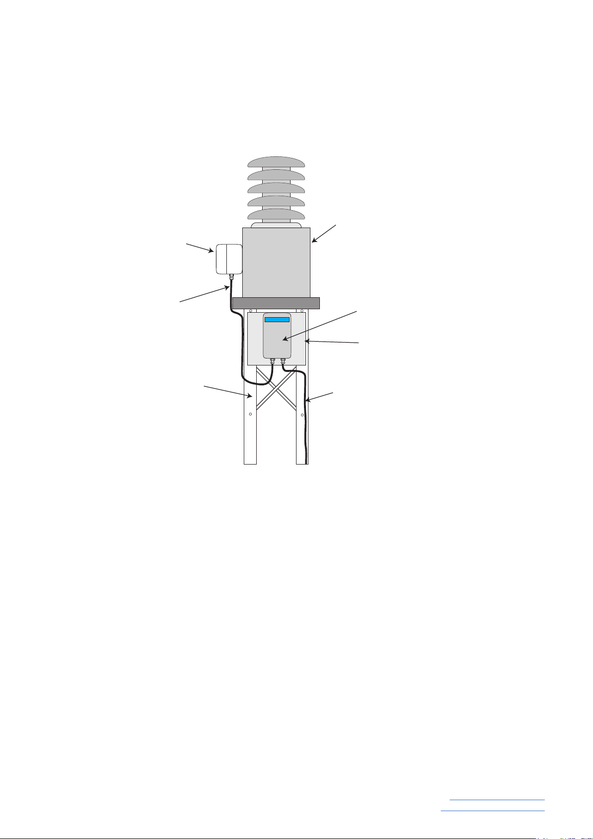
N.B. A mounting plate or bracket will be required
to secure the SCM to the CVT structure. Since
there is a wide variety of support structures used
in substations this bracket is NOT provided with the
PQSensor™ and will normally be sourced locally.
4.2 Installation in Hot Climates
In climates where ambient temperatures can ex-
ceed 40˚C it is highly recommended to mount the
SCM in a location that will afford the maximum
shade from direct sunlight. While the PQSensor™
is rated for temperatures up to 65˚C in warmer cli-
mates it is prudent to limit exposure to direct sun-
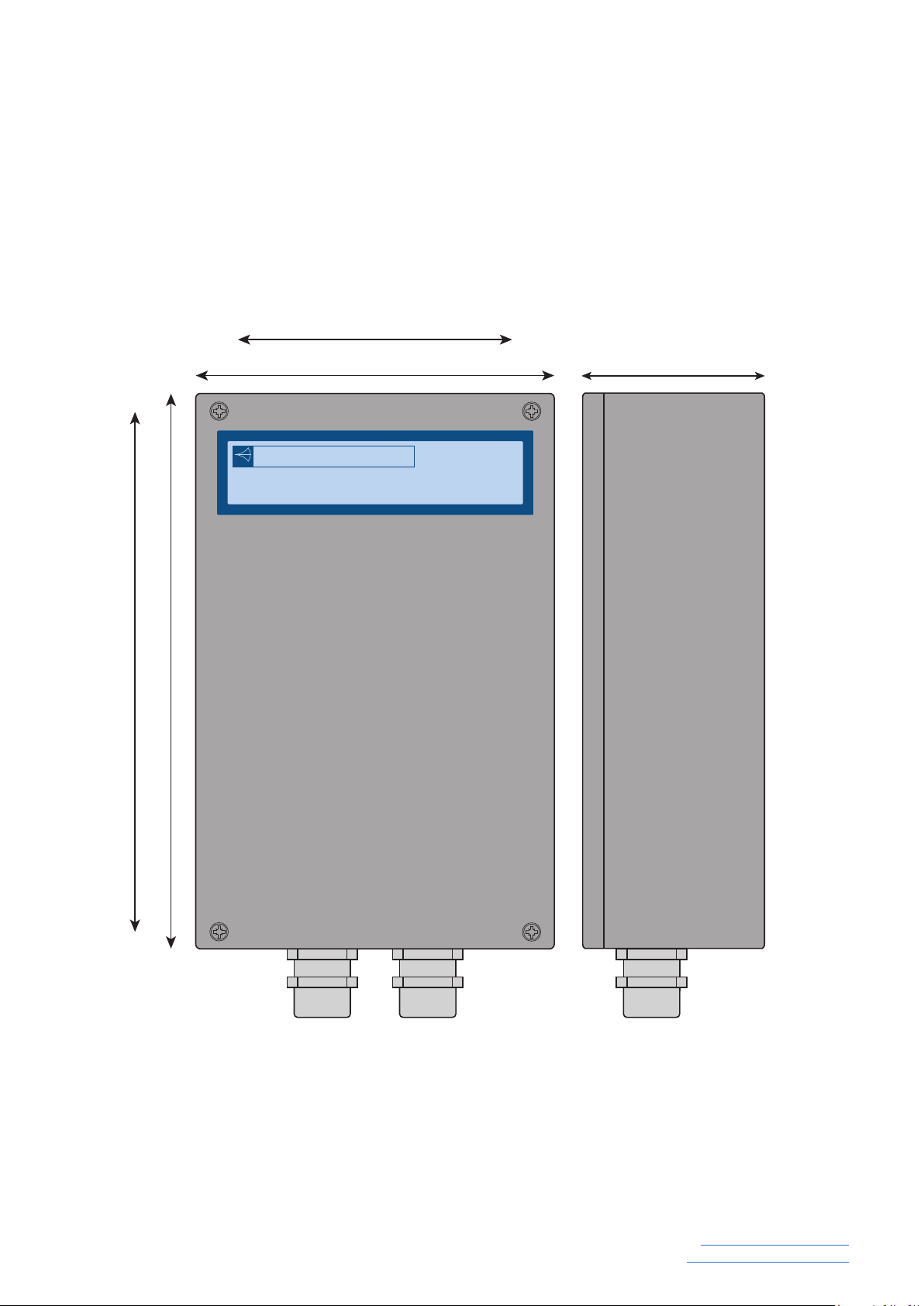
light. This is best achieved by using a mounting
plate at least 500mm wide which is fitted on the
shaded side of the CVT structure. A sun shade can
also be provided for such installations.
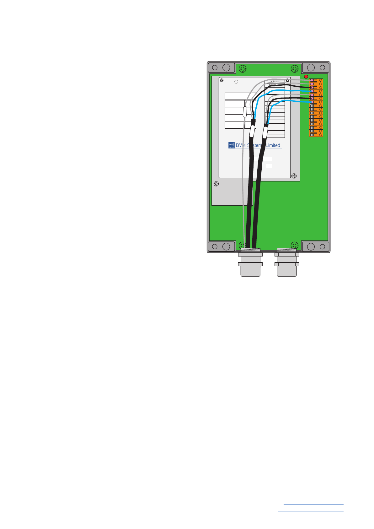
4.3 Installing the Interconnecting Cable
The Interconnecting cable is 3m in length and is
pre-terminated at both ends for connection between
the CVT secondary terminal box and the SCM en-
closure. The interconnecting cable should be wired
between the MU in the CVT secondary terminal
box and the SCM using the SWA cable glands sup-
plied. First terminate the connections in the SCM
as shown in Figure 3 and the drawing in Appendix
IV and then terminate the other end of the cable
on the MU in the CVT terminal box. A full wiring
diagram for the Interconnecting Cable in contained
in Appendix IV. The interconnecting cable should be securely xed to the CVT structure at as
many points as necessary to ensure there are no loose sections of cable.
4.4 Supply Voltage and Output Signal connection
In addition to the connections to the Measurement Unit the supply voltage and the output signal
need to be connected. These connections should be made using stranded cable with a mini-
mum size of 1mm2.
The PQSensor™ accepts a universal supply and can be powered from 110V ac, 230V ac or
80 - 250V dc. A ground/earth connection must always be made to pin 3 of the PQSensor™ user
connection terminal block.
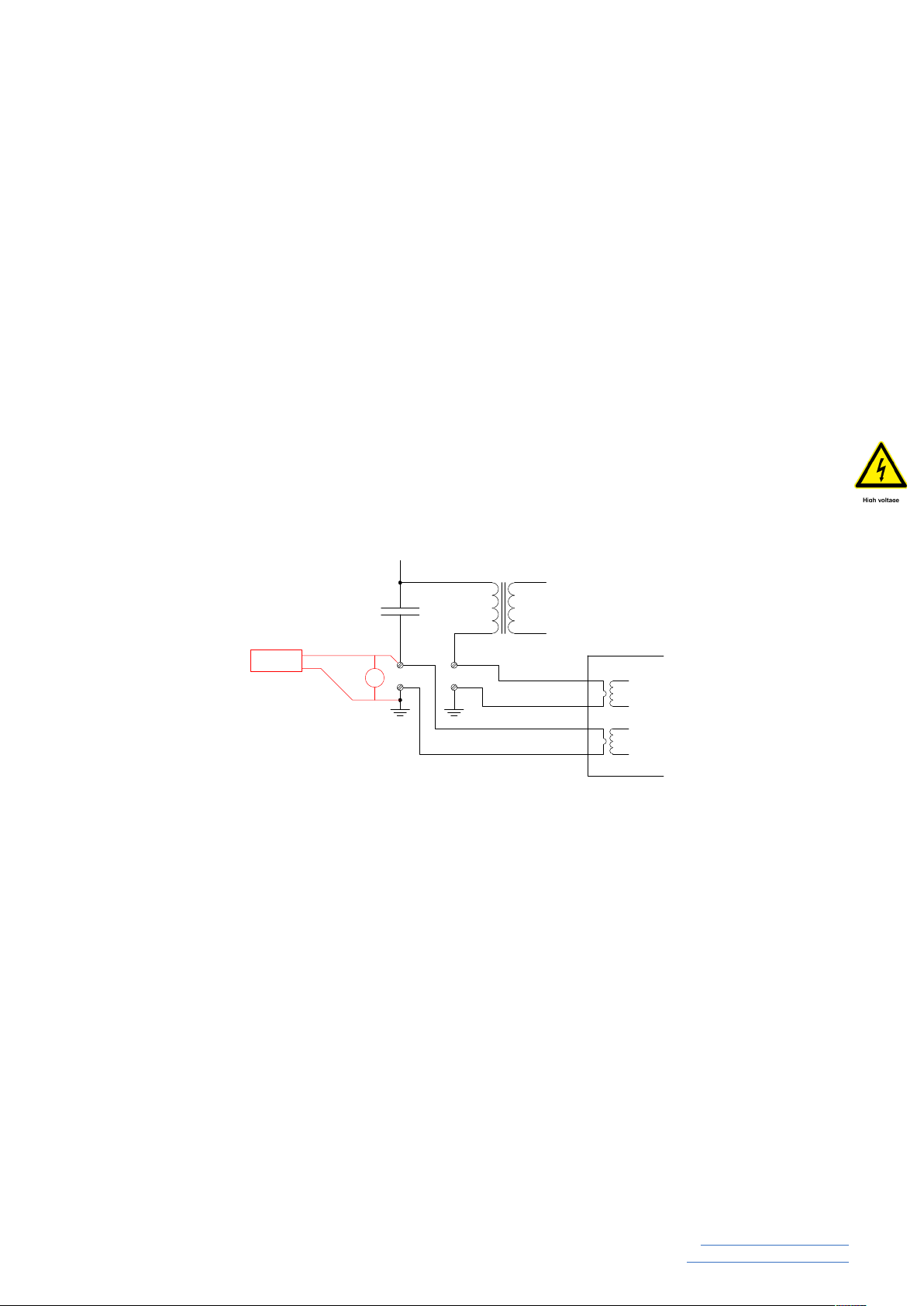
The nominal output signal from the PQSensor™ is of the order of 60V ac so appropriate safety
precautions should be taken when working with a voltage of this level. For safety purposes it
should be assumed that when the PQSensor™ is powered on there is always a voltage of 60V
ac present on the output terminals.
The PQSensor™ is intended to be used with recording equipment that has an input impedance
of greater than 1Mohm.
Supply Voltage:- 110/230V ac, 88 - 250Vdc
Part No. 18-0049-
PQSensor™
Serial No.
16. Earth
15. Screen (White)
14. LCCT (Black)
13. LCCT (Blue)
12. Screen (White)
11. HCCT (Black)
10. HCCT (Blue)
9. Earth
8. Aux (Cmn)
7. Aux
6. Earth
5. O/P (Cmn)
4. O/P
3. Earth
2. Neutral / -
1. Live / +
CVT Serial Number
Factory Test Voltage
FieldTest Voltage
Date Sign
Date Sign
Output (V)
Output (V)
O/P Adj.
HCCT
LCCT
EARTH
Figure 3