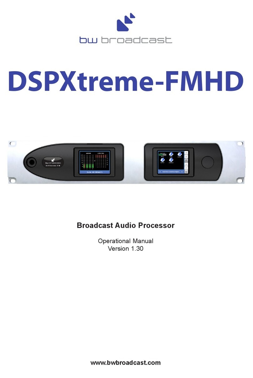
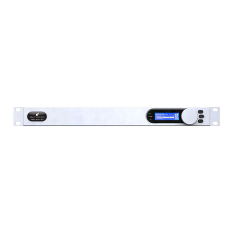
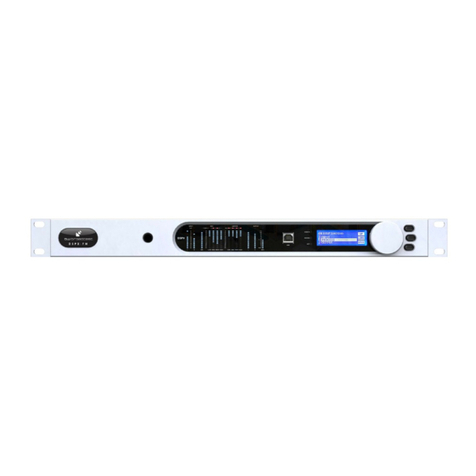
BW Broadcast DSPXmini-AM Quick start guide

DSPXmini-AM
Broadcast Audio Processor
Operational Manual
Version 1.01
www.bwbroadcast.com

Table Of Contents
2
Table Of Contents
Warranty 3
Safety 4
Forward 6
Introduction to the DSPXmini-AM 7
DSPXmini-AM connections 8
DSPXmini-AM metering and status LEDs 9
Quickstart 10
An introduction to audio processing 11
Source material quality and HF Boost 12
Low pass filtering 13
The DSPXmini-AM and its processing structure 14
Processing block diagram 15
The DSPXmini-AM menu system 16
The menu structure 17
Processing Parameters 18
Setting up the processing on the DSPXmini-AM 22
Getting the sound that you want 27
Managing Presets 29
Factory presets 30
Remote control of the DSPXmini-AM 31
Remote trigger port 37
Security code lock 38
Clock based control 39
Specifications 40
Preset sheet Appendix A

Warranty
3
WARRANTY
BW Broadcast warrants the mechanical and electronic components of this product to be free of defects in mate-
rial and workmanship for a period of one (1) year from the original date of purchase, in accordance with the war-
ranty regulations described below. If the product shows any defects within the specified warranty period that are
not due to normal wear and tear and/or improper handling by the user, BW Broadcast shall, at its sole discretion,
either repair or replace the product.
If the warranty claim proves to be justified, the product will be returned to the user freight prepaid.
Warranty claims other than those indicated above are expressly excluded.
Return authorisation number
To obtain warranty service, the buyer (or his authorized dealer) must call BW Broadcast during normal business
hours BEFORE returning the product. All inquiries must be accompanied by a description of the problem. BW
Broadcast will then issue a return authorization number.
Subsequently, the product must be returned in its original shipping carton, together with the return authorization
number to the address indicated by BW Broadcast. Shipments without freight prepaid will not be accepted.
Warranty regulations
Warranty services will be furnished only if the product is accompanied by a copy of the original retail dealer’s
invoice. Any product deemed eligible for repair or replacement by BW Broadcast under the terms of this war-
ranty will be repaired or replaced within 30 days of receipt of the product at BW Broadcast.
If the product needs to be modified or adapted in order to comply with applicable technical or safety standards
on a national or local level, in any country which is not the country for which the product was originally devel-
oped and manufactured, this modification/adaptation shall not be considered a defect in materials or workman-
ship. The warranty does not cover any such modification/adaptation, irrespective of whether it was carried out
properly or not. Under the terms of this warranty, BW Broadcast shall not be held responsible for any cost result-
ing from such a modification/adaptation.
Free inspections and maintenance/repair work are expressly excluded from this warranty, in particular, if caused
by improper handling of the product by the user. This also applies to defects caused by normal wear and tear, in
particular, of faders, potentiometers, keys/buttons and similar parts.
Damages/defects caused by the following conditions are not covered by this warranty:
Misuse, neglect or failure to operate the unit in compliance with the instructions given in BW Broadcast user or
service manuals.
Connection or operation of the unit in any way that does not comply with the technical or safety regulations
applicable in the country where the product is used.
Damages/defects caused by force majeure or any other condition that is beyond the control of BW Broadcast.
Any repair or opening of the unit carried out by unauthorized personnel (user included) will void the warranty.
If an inspection of the product by BW Broadcast shows that the defect in question is not covered by the war-
ranty, the inspection costs are payable by the customer.
Products which do not meet the terms of this warranty will be repaired exclusively at the buyer’s expense. BW
Broadcast will inform the buyer of any such circumstance. If the buyer fails to submit a written repair order within
6 weeks after notification, BW Broadcast will return the unit C.O.D. with a separate invoice for freight and pack-
ing. Such costs will also be invoiced separately when the buyer has sent in a written repair order.
Warranty transferability
This warranty is extended exclusively to the original buyer (customer of retail dealer) and is not transferable to
anyone who may subsequently purchase this product. No other person (retail dealer, etc.) shall be entitled to
give any warranty promise on behalf of BW Broadcast.
Claims for damages
Failure of BW Broadcast to provide proper warranty service shall not entitle the buyer to claim (consequential)
damages. In no event shall the liability of BW Broadcast exceed the invoiced value of the product.
Other warranty rights and national law
This warranty does not exclude or limit the buyer’s statutory rights provided by national law, in particular, any
such rights against the seller that arise from a legally effective purchase contract. The warranty regulations men-
tioned herein are applicable unless they constitute an infringement of national warranty law.

Safety Instructions
4
DETAILED SAFETY INSTRUCTIONS:
All the safety and operation instructions should be read before the appliance is operated.
Retain Instructions:
The safety and operating instructions should be retained for future reference.
Heed Warnings:
All warnings on the appliance and in the operating instructions should be adhered to.
Follow instructions:
All operation and user instructions should be followed.
Water and Moisture:
The appliance should not be used near water (e.g. near a bathtub, washbowl, kitchen sink, laundry tub, in a
wet basement, or near a swimming pool etc.).
The appliance should not be exposed to dripping or splashing and objects filled with liquids should not be
placed on the appliance.
Ventilation:
The appliance should be situated so that its location or position does not interfere with its proper ventilation.
For example, the appliance should not be situated on a bed, sofa rug, or similar surface that may block the
ventilation openings, or placed in a built-in installation, such as a bookcase or cabinet that may impede the
flow of air through the ventilation openings.
Heat:
The appliance should be situated away from heat sources such as radiators, heat registers, stoves, or other
appliance (including amplifiers) that produce heat.
Power Source:
The appliance should be connected to a power supply only of the type described in the operating instructions
or as marked on the appliance.
Grounding or Polarization:
Precautions should be taken so that the grounding or polarization means of an appliance is not defeated.
Power-Cord Protection:
Power supply cords should be routed so that they are not likely to be walked on or pinched by items placed
upon or against them, paying particular attention to cords and plugs, convenience receptacles and the point
where they exit from the appliance.
Cleaning:
The appliance should be cleaned only as recommended by the manufacturer.
Non-use Periods:
The power cord of the appliance should be unplugged from the outlet when left unused for a long period of
time.
This symbol, wherever it appears,
alerts you to the presence of
uninsulated dangerous voltage inside
the enclosure—voltage that may be
sufficient to constitute a risk of shock.
This symbol, wherever it appears, alerts
you to important operating and mainte-
nance instructions in the accompanying
literature. Read the manual.
CAUTION: To reduce the risk of electrical shock, do not
remove the cover. No user serviceable parts inside. refer
servicing to qualified personnel.
WARNING: To reduce the risk of fire or electrical shock, do
not expose this appliance to rain or moisture.
SAFETY INSTRUCTIONS

Safety Instructions
5
Object and Liquid Entry:
Care should be taken so that objects do not fall and liquids are not spilled into the enclosure through open-
ings.
Damage Requiring Service:
The appliance should be serviced by qualified service personnel when:
- The power supply cord or the plug has been damaged; or
- Objects have fallen, or liquid has been spilled into the appliance; or
- The appliance has been exposed to rain; or
- The appliance does not appear to operate normally or exhibits a marked change in performance; or
- The appliance has been dropped, or the enclosure damaged.
Servicing:
The user should not attempt to service the appliance beyond that is described in the Operating Instructions.
All other servicing should be referred to qualified service personnel.
CE CONFORMANCE: This device complies with the requirements of the EEC Council
Directives: 93/68/EEC (CE Marking); 73/23/EEC (Safety – low voltage directive);
2004/108/EC (electromagnetic compatibility). Conformity is declared to those standards:
EN50081-1, EN50082-1.
WARNING: This equipment generates, uses, and can radiate radio frequency energy.
If not installed and used in accordance with the instructions in this manual it may cause
interference to radio communications. It has been tested and found to comply with the
limits for a Class A computing device (pursuant to subpart J of Part 15 FCC Rules),
designed to provide reasonable protection against such interference when operated in
a commercial environment. Operation of this equipment in a residential area is likely to
cause interference, at which case, the user, at his own expense, will be required to take
whatever measures may be required to correct the interference.
CANADA WARNING: This digital apparatus does not exceed the Class A limits for radio noise emis-
sions set out in the Radio Interference Regulations of the Canadian Department of Communications.
Le present appareil numerique n'emet pas de bruits radioelectriques depassant les limits applicables
aux brouillage radioelectrique edicte par le ministere des Communications de Canada.

Forward
6
FORWARD
Thank you for your purchase of the DSPXmini-AM digital audio broadcast processor.
Over the last decade the staff at BW have observed broadcast processors from afar with fascination and intrigue
and shared a keen interest in digital audio processing. In January 2002 we decided on a whim that it was time
to have a go at designing our own digital audio processor. We knew that if we were going to design an audio
processor we had to do it the BW way and make the processor the most cost effective fully featured all-in-one
broadcast processor on the planet. We knew we didn't have the decades of processing experience that the other
manufacturers had but what we did have was a desire to research the project for as long as necessary to get the
job done. We also knew that by combining the research with BW's embedded systems skills and ability to manu-
facture low-cost cutting edge products we would ensure that the DSPX would be a winner. The one aim, to make
an audio processor that offered all of the features found in the other more costly processors but at a fraction of
the price.
Why DSPX? Like most products the concept is conceived, nameless. The name DSPX came about for several
reasons. Firstly the BW team couldn't decide on a name we liked so the concept became DSP processor X. As
the project developed it soon became clear that the processor was to be a processor for all broadcast seasons
and so in true algebraic fashion X represents many things. DSPX was born.
Once again, thank you for your purchase; we hope you enjoy the DSPXmini-AM!
BW Broadcast Team

Introduction
7
INTRODUCTION TOTHE DSPXMINI-AM
The BW Broadcast DSPXmini-AM is a new generation of digital audio signal processor that can be used to proc-
ess audio for AM broadcasting. Using the latest multi-band DSP technology the DSPXmini-AM offers a versatile
and powerful tool in creating a loud and intelligible on-air presence.
What's Under the Lid?
The DSPXmini-AM is driven by a fast 8 bit micro-controller which controls an array of specialised analogue and
digital circuits. These include 24-bit A/D and D/A converters, analogue level control circuitry, 6 x 24 bit DSP's,
an ethernet port, a trigger port, an RS232 port, an LCD screen and memory devices to hold the software and
firmware.
The Processing Architecture
After input selection the 24-bit digital audio signal is passed through conditioning circuitry before being split to
four bands by a phase matched crossover. Each band is processed by multiband RMS leveller which corrects for
input level variations and also improves consistency. Each band is further processed by intelligent audio limiter.
The following distortion cancelling clipping ensures your signal is kept to a strict maximum while maintaining
clear sound.
The easy to use front panel control system with LCD afford the user with ease of use and setup.
Comprehensive control of every processing parameter is available to the user both from the front panel control
system and by remote (computer) control.
At a fraction of the size, weight and price of its rivals, the DSPXmini-AM is small but serious AM processor.
Dynamic, fresh & innovative...
... The DSPXmini-AM

Connections
8
LOAD PRESET
REMOTE
AES/EBU
EDIT
UP
LOAD
SAVE
DSPXmini
OUTPUT
PROCESS
INPUT
UP
LOAD
U1=BASS FACE INS
DEL
DONE
ENTER PASSCODE
INS
DEL
DONE
ENTER NEW PASSCODE
3779
U2=ROUND FACE
U3=CLASSICAL 3
(A)
SAVE PRESET UP
GO
U1=BASS FACE
U2=ROUND FACE
U3=CLASSICAL 3
(A)
INS
DEL
DONE
NAME PRESET U2
MY PRESET 3
UP
LOAD
SAVE
DSPXmini
OUTPUT
PROCESS
INPUT
DSPXmini-AM
ANALOGUE
INPUTS
AES / EBU
INPUT
RS232
&
TRIGGER PORT
LAN
PORT
GND
LIFT
MAINS POWER INPUT
STATUS
LEDS
SOFT
KEYS
CONTROL
KNOB
DSPXmini-AM FRONT AND REAR PANELS
SYNC
INPUT
ANALOGUE
OUTPUTS
AES / EBU
OUTPUT

Meters And Status LEDs
9
DSPXMINI-AM METERING
The DSPXmini-AM metering is accesable at any time by pressing the middle soft key on the front panel. It
shows instant IO meters as well as all processing metering.
I/O metering
The input meters show the level of the input audio. The meters are ‘hooked in’ to the DSP code after the input
level selection and mode options.
The output meters represent the level in dB below full scale output. This output level is the peak output level of
the processing and has nothing to do with the actual output level set by the analogue and digital output level
options.
The output meters show a smaller dynamic range compared to the input ones. This reflects the smaller dynamic
range of the audio once processed by the DSPXmini-AM. If we were to have used the same scale as the input
metering we would not see a lot of activity on the bars.
The IO meters follows an approximation of the PPM level of the audio waveform. Please notice that if you are
using asymmetrical clipping, the output meters won't reflect the asymmetry. They always show levels up to
100% modulation.
Multi-band AGC
The first four gain reduction meters show the gain reduction of the multi-band AGC. The range shown is -21dB
to +21dB in 3dB steps.
There is only one meter per stereo channel and the value shown is the largest gain reduction of the left and right
channels. Under normal operation (with a stereo audio feed) this is fine but you may observe strange metering if
the channels are not very balanced in level.
Multi-band limiter
The second four gain reduction meters show the gain reduction of the multi-band limiter. The range shown is
0dB to -22.5dB in 1.5dB steps.
There is only one meter per stereo channel and the value shown is the largest gain reduction of the left and right
channels. Under normal operation (with a stereo audio feed) this is fine but you may observe strange metering if
the channels are not very balanced in level.
STATUS LEDS
The DSPXmini-AM front panel contains three status LEDS.
REMOTE: Indicates that the DSPXmini-AM is currently talking to a remote computer. This will flash during
an update of the firmware or remote control with the remote control application.
AES/EBU: Indicates the presence of a valid AES/EBU signal connected to the digital audio input of the
DSPXmini-AM.
EDIT: Indicates that you are currently editing a parameter
REMOTE
AES/EBU
EDIT

Quick Start
10
QUICK START
1. Install the DSPXmini-AM into the rack.
2. Connect AC power to the unit, and turn on the power.
3. Connect the analogue or digital audio input.
4. Select the analogue or digital input as the source of the processing with the 'INPUT SELECTION' parameter
which can be found in the 'INPUT' menu. Apply audio and observe the input meters. For analogue inputs, adjust
the 'INPUT’ menus 'INPUT LEVEL CONTROL' so that the input meters do not clip. We recommend setting the
mixing board or audio source to full level output (even clipping) prior to adjusting this control. This ensures that
the processor's A/D converter will not clip under any conditions. Optionally, select mono options (L, R, L+R).
5. Connect the audio outputs as required and set the output level settings for the analogue and digital outputs to
match any external links or transmitters that require left and right audio inputs or an AES/EBU input.
You can use the built-in tone generator to set the output levels. Navigate to Oscillator in the Output menu, set it
to Sine, set the Amplitude to 60% and adjust Analog Out Level until your transmitter reads 50% modulation (the
10% difference is to account for possible overshoots in the transmission).
6. Select a factory preset (see Managing presets).
7. Navigate to 'OUTPUT' menu and adjust the low-pass filter setting as required. This sets the occupied band-
width of the AM transmission.
8. Navigate to 'INPUT' menu and adjust the high-pass filter setting.
9. You're on the air!
Further information on each parameter is contained in the 'menu structure' and 'setting up the processing' sec-
tions of this manual.

Introduction To Audio Processing
11
INTRODUCTION TOAUDIO PROCESSING
Most audio processors use a combination of compression, limiting and clipping to 'funnel' the dynamic range
down, reducing the peak to average ratio in each stage. A cascaded arrangement of compressor, limiter and
clipper produces the best results. The first stage of processing usually operates in a slow manner, the process-
ing getting progressively faster and more aggressive as the audio passes through the chain. The instantaneous
peak clipper or look-ahead limiter is the final stage of the chain and sets the final peak level.
The images below illustrate a section of audio as it passes through a typical audio processor.
The first image to the right is an unprocessed section of audio.
The images that follow represent compression of the input wave-
form, followed by limiting and then finally peak clipping.
Compression
Compression reduces the dynamic range of the audio waveform
slowly in a manner similar to a trained operator riding the gain.
Compression is usually performed on the RMS level of the audio
waveform and the ratio of compression is usually adjustable.
Compression is usually gated to prevent gain riding and suck-up
of noise during silence or quiet periods.
Limiting
Limiting is a faster form of compression that employs faster time
constants and higher ratios to produce a denser sound while
controlling peaks based upon the peak level of the audio wave-
form. Excessive limiting can create a busier packed wall of sound
effect.
Clipping
Clipping the audio waveform will not produce any audible side
effects if performed in moderation. Excessive clipping will pro-
duce a form of distortion that produces a tearing or ripping
sound. Clipping can also be used as an effective method of high
frequency peak control when used in conjunction with distortion
controlling filtering.
Look-ahead limiting
Often used instead of a clipper in systems that feed bit rate reducing audio codecs, look-ahead limiting exam-
ines the audio waveform and prepares a gain control signal in advance of the delayed audio waveform arriving.
This prevents overshoots while minimising distortion. A look-ahead limiter behaves in the same way as a soft
clipper. Competent look-ahead limiters will usually be of the multi-band variety.

Source quality and HF boost (pre-emphasis)
12
SOURCE MATERIAL QUALITY
The DSPXmini-AM has the ability to substantially improve the quality of your ON-AIR broadcast. However
the DSPXmini-AM can only work with what you provide it. The best performance will be obtained when the
DSPXmini-AM is fed with very clean source material. After dynamic range reduction is performed, poor quality
source material will sound poorer when processed with the DSPXmini-AM.
We strongly advise against the use of MP3's and other compressed audio formats for audio storage. If you must
use compressed audio we advise rates of 256 kbps and higher, but linear formats are always to be preferred.
Compressed audio formats employ frequency masking data reduction techniques to reduce the bit-rate. Through
re-equalisation the DSPXmini-AM can violate the frequency masking characteristics of the bit reduction process,
creating distortion that was inaudible prior to the DSPXmini-AM processing.
HF BOOST (PRE-EMPHASIS)
Todays typical AM receivers have narrow bandwidth (typically 3 kHz) and it is usually beneficial to compensate
for the high-end roll-off by boosting the high frequencies in the processor. This can help restore some of the
high-end response and brightness. The DSPXmini-AM has an HF equalizer that can provide as much as 20 dB
of high end boost. The graph below illustrates pre-emphasis curves in 2 dB steps. The blue curves show the
response with the shape control set to 1, and the red ones show the response with the shape control set to 10.
HF boost curves (varying HF Gain from 2 to 20 dB, blue HF Shape=1, red HF Shape=10)
20.0 Hz 50.0 100 200 500 1.00K 2.00K 5.00K 10.0K
+20.00
+18.00
+16.00
+14.00
+12.00
+10.00
+8.00
+6.00
+4.00
+2.00
0.00
dB +20.00
+18.00
+16.00
+14.00
+12.00
+10.00
+8.00
+6.00
+4.00
+2.00
0.00
dB
BW Broadcast
The HF curve can be shifted slightly lower or higher in frequency, with a shape control. Illustrated below are
curves at 10 dB and 20 dB gain, with the HF shape control varied from 1 to 9 in steps of 2. To provide NRSC-1
pre-emphasis, the HF Gain should be set to 10 dB and the HF Shape to 8.
20.0 Hz 50.0 100 200 500 1.00K 2.00K 5.00K 10.0K
+20.00
+18.00
+16.00
+14.00
+12.00
+10.00
+8.00
+6.00
+4.00
+2.00
0.00
d
B+20.00
+18.00
+16.00
+14.00
+12.00
+10.00
+8.00
+6.00
+4.00
+2.00
0.00
d
B
BW Broadcast
HF boost curves (varying HF Shape from 1 to 9; violet 20 dB gain, orange 10 dB gain)

Low pass filtering
13
LOW PASS FILTERING
To accommodate various bandwidth limitation requirements in different countries, the DSPXmini-AM has an
adjustable low pass filter. The filter is adjustable from 4 kHz to 10 kHz in 500 Hz steps. To comply with the
NRSC-1 standards (10 kHz bandwidth for analog AM, 8 kHz bandwidth for Hybrid AM IBOC or 5 kHz bandwidth
for Hybrid AM IBOC transmission) set the filter to 10 kHz, 7.5 kHz and 4 kHz respectively. The graph below
shows all the low pass filter curves. You can use it to determine the correct setting for the required bandwidth (or
mask) in your country.
Low pass filter curves: 4.0, 4.5, 5.0, 5.5, 6.0, 6.5, 7.0, 7.5, 8.0, 8.5, 9.0, 9.5 and 10 kHz
DSPXmini low pass filters
100.00 2000.00 4000.00 6000.00 8000.00 10000.00 11500.00 Hz
-90.00
-80.00
-70.00
-60.00
-50.00
-40.00
-30.00
-20.00
-10.00
0.00
dB

Processing Structure
14
THE DSPXMINI-AM AND ITS PROCESSING STRUCTURE
The DSPXmini-AM broadcast audio processor is intended to be used for processing audio prior to broadcast on
AM. It employs distortion controlled clippers to limit the peaks of the signal. Distortion controlled clipping pro-
duces harmonic distortion which if used moderately can produce a very loud sound but can result in a ripping or
tearing sound if used excessively (overdriven).
The AM path is also low-pass filtered, to provide bandwidth limitation as required for AM broadcasting.
THE PROCESSING PATH
Input selection and conditioning
The DSPXmini-AM offers the user input selection (analog or digital input), stereo or mono (L, R or L+R) oper-
ation and high pass filter selection.
Bass enhancement
The DSPXmini-AM offers a bass enhancement via peaking filter that can be set to provide up to 6dB of gain
on one of four frequencies with a choice of 4 Q's. This can be thought of as a simple bass parametric.
Xover
The DSPXmini-AM employs phase matched filters to split the audio spectrum into 4 bands while maintaining
sonic transparency.
Multi-band AGC
The DSPXmini-AM processes each band with RMS based levellers. Each bands gain control processing
function can be configured in different manners to provide different effects. Adjustable timing constants, drive
and gating afford the user with full control of this important re-equalisation stage of the processor.
Multi-band limiters
Each band has its own dynamic peak limiter. Complex algorithm is used to intelligently adapt to program
audio and control it in a natural way. Dual time constants are adjustable as well as input drives.
Mixer
The four bands are mixed together at this stage, allowing overall EQ adjustment.
Bass clipper
The DSPXmini-AM peak limits (clips) and filters the low frequencies before being fed to the final clipper
stages.
Distortion controlled clipper
The DSPXmini-AM main clipper uses sophisticated algorithms to produce tightly peak controlled output and
control the distortion.
Output processing
The DSPXmini-AM output has an adjustable low-pass filter to comply with NRSC, ITU-R and otherstandards,
tilt equalization to compensate for a non-DC path in the transmitter and a tone generator to facilitate set-up
and alignment.

Block Diagram
15
ANALOG
DIGITAL
A/D
SRC
LOW
AGC
MID1
AGC
HIGH
AGC
INPUT MB AGC
LPF
BPF
BPF
HPF
BASS
PEAK
MID2
AGC
LOW
LIM
MID1
LIM
HIGH
LIM
MB LIM
MID2
LIM
LPF
BASS CLIP
LPF
OUTPUT
DSPXmini-AM PROCESSING BLOCK DIAGRAM
CLIP
HF
BOOST
LP FREQ
ASYMM
ANALOG
D/A
OSC
DIGITAL
SRC
SYNC

Menu System Overview
16
MENU SYSTEM OVERVIEW
This section presents an overview of the four main menus and thier submenus and any parameters that are con-
tained in them.
INPUT: Contains all the controls that affect input selection, level control and signal conditioning.
PROCESS: Contains all the controls that affect the processing.
OUTPUT: Contains all the controls that affect output selection, level control and signal conditioning.
SCHEDULE: Contains all the real time clock controls for switching presets (Dayparting).
SYSTEM: Contains all the system controls (non processing) such as remote control and security.

Menu Structure
17
MENU STRUCTURE
MENU: INPUT
INPUT SOURCE
ANALOG LEVEL
RIGHT TRIM
MODE
HP FILTER
MENU: PROCESS
MENU: EQ
PEAKING BASS GAIN
PEAKING BASS FREQ
PEAKING BASS Q
HF SHAPE
HF GAIN
MENU: MULTI-BAND AGC
MENUS: BANDS 1-4
DRIVE
ATTACK
DECAY
GATE
MENU: MULTI-BAND LIMITERS
MASTER LIMITER DRIVE
BAND 1
DRIVE
LIMITER ATTACK
LIMITER DECAY
COMPRESSOR ATTACK
COMPRESSOR DECAY
BAND 2
DRIVE
LIMITER ATTACK
LIMITER DECAY
COMPRESSOR ATTACK
COMPRESSOR DECAY
BAND 3
DRIVE
LIMITER ATTACK
LIMITER DECAY
COMPRESSOR ATTACK
COMPRESSOR DECAY
BAND 4
DRIVE
LIMITER ATTACK
LIMITER DECAY
B3>B4 COUPLING
HF CLIPPING
MENU: MIXER
BAND 1 MIX LEVEL
BAND 2 MIX LEVEL
BAND 3 MIX LEVEL
BAND 4 MIX LEVEL
MENU: CLIPPERS
BASS CLIP
MAIN CLIP DIST CTRL
FINESSE
HARDNESS
MAIN CLIP DRIVE
MENU: OUTPUT
LP FILTER
TILT EQ
TILT FREQ
ASYMMETRY
POLARITY
ANALOG OUT LEVEL
MENU: TONE GENERATOR
OSCILLATOR
FREQUENCY
AMPLITUDE
ANALOG OUT LEVEL
MENU: DIGITAL
DIGITAL LEVEL
SAMPLING RATE
MENU: SCHEDULE (X) REPRESENTS 0-7
TIME
DAYPARTING ON/OFF
TIME CALIBRATION
DAYPARTS 1-4
DP(X) ON/OFF
DP(X) START TIME
DP(X) TIME ON (LENGTH)
DAYPARTS 5-8
DP(X) ON/OFF
DP(X) START TIME
DP(X) TIME ON (LENGTH)
MENU: SYSTEM
LCD CONTRAST
TRIGGER PORT
CODE LOCK
REMOTE SOURCE
MENU: LAN CONFIG
IP
DG (DEFAULT GATEWAY)
SM (SUBNET)
MA1 (MAC ADDRESS PART1)
MA2 (MAC ADDRESS PART2)
PORT
MENU: ABOUT
VERSION
CONCEPT
HARDWARE
CONTROL SYSTEM
PROCESSING
REMOTE APPLICATION
BOOTLOAD

Processing Parameters
18
PROCESSING PARAMETERS
The 'INPUT' menu contains options relating to the control and conditioning of the audio inputs.
'INPUT SOURCE' This parameter allows you to select the between the analog and digital inputs as the
source for the processing.
'ANALOGUE INPUT A/D CLIP LEVEL' This parameter allows you to set the analogue input level with refer-
ence to the DSPXmini-AM's A/D Converter. This would normally be set to +24dBu if driving the DSPXmini-
AM from professional audio equipment. When adjusting make sure that the input audio meters NEVER
show clipping under any conditions.
'RIGHT TRIM': This parameter allows you to adjust the right channels gain in small increments to BALANCE
out any small gain discrepancies between the left and right channels. The range is +/- 3dB.
'MODE': This parameter allows you to select different mono options as well as the default stereo option.
There is also the ability to swap the left/right channels.
'HIGH PASS FILTER' This parameter allows you to select from a variety of high pass filters. You can select
from 20 Hz, 30 Hz, 40 Hz, 50 Hz and 60 Hz. You also have the ability to bypass the high pass filter with the
'OFF option. The high pass filter can be used to reduce rumble or can be effective in removing low frequency
energy that most AM receivers can't reproduce. We suggest you set the high pass filter to 30 Hz.
The 'PROCESS' menu allows access to all of the processing blocks that make up the DSPXmini-AM.
There are only sub-menus inside the 'PROCESS' menu. The submenus are laid out in the same configu-
ration as the signal path through the DSPXmini-AM.
The 'EQ' menu contains the low frequency enhancement filters which are used to provide bass enhance-
ment and high freqeuncy equalizer to provide high-end boost (pre-emphasis).
‘PEAKING BASS EQUALIZER’ A pseudo parametric style bass equalizer control that allows you to
sweet tune the bass. Four frequencies, amplitudes and Q's are provided giving you 64 different bass
curves to select from. Frequencies selectable: 60 Hz, 76 Hz, 95 Hz and 120 Hz. Q's selectable: 0.4, 1, 2
and 4. Gains selectable: 0 dB, 1.5 dB, 3 dB, 4.5 dB, 6 dB.
'HF SHAPE' Shifts the HF boost curve lower (values towards 1) or upper (values towards 10) in fre-
quency. Lower numbers refer to lower frequencies and will boost more mid frequencies as well as the
high frequencies. Higher numbers refer to higher frequencies and will put more emphasis on the higher
frequencies than on the mid frequencies.
‘HF GAIN’ Adjusts the high frequency gain from 0 dB (no high-end boost) up to 20 dB. Some high-end
boost might be beneficial to compensate for the typical receiver high-end roll off. However, excessive
high-end boost will be counteracted by the B4 AGC levelling action.
The ‘MULTI-BAND AGC’ is designed to re-equalize the program material and create a consistent tonal bal-
ance while maintaining a consistent output level based on the RMS level of the program material.
‘B1-4’
‘DRIVE’ Controls the drive into the AGC. 0dB drive corresponds to a gain reduction of 0dB, the mid-
way point. The drive can be increased or decreased by up to 12dB. You may need to increase the
drive a little as you go up through the bands to compensate for the fact that music has less energy in
the higher frequency spectrum compared to low frequencies.
‘ATTACK’ Controls the attack rate of the AGC, The time the AGC takes to respond to an increase of
input level. The attack time can be varied between 1 and 10 which corresponds to 100mS to 10S on
a semi-exponential scale.
‘DECAY’ Controls the release/decay rate of the AGC, the time the AGC takes to respond to a
decrease of input level. The DECAY time can be varied between 1 and 10 which corresponds to
100mS to 30S on a semi-exponential scale.
‘GATE THRESHOLD’ The gate function prevents ‘suck-up’ of noise during periods of silence or low

Processing Parameters
19
level audio. The level can be adjusted to turn on when the input drops to a level from -20dB to -40dB.
The gate can also be switched off or forced on. The gate when turned on will cause the gain reduc-
tion to move towards the resting 0dB level
The 'MULTI-BAND LIMITERS' peak limit each of the bands to prevent distortion in the processors clipping
peak control system.
‘MASTER LIMITER DRIVE’ Sets the drive into the multi-band limiter. This control allows a - 6dB to
+12dB adjustment.
'B1-3'
'DRIVE' Controls the drive into the limiter. The drive can be increased or decreased by up to 6dB.
'PEAK ATTACK' Controls the attack rate of the limiter, the time the limiter takes to respond to an
increase of input level. The attack time can be varied between 1 (fast) and 10 (slow).
'PEAK DECAY' Controls the peak release/decay rate of the limiter, the time the limiter takes to
respond to a decrease of input level. The DECAY time can be varied between 1 (fast) and 10 (slow).
'AVG ATTACK' Controls the average attack rate of the limiter. The attack time can be varied between
1 (fast) and 10 (slow). The AVG attack control determines the dynamics of the dual time constant sys-
tem and how audio control is shared between the peak and average circuits.
'AVG DECAY' Controls the average release/decay rate of the limiter, the time the limiter takes to
respond to a decrease of input level. The DECAY time can be varied between 1 (fast) and 10 (slow).
B4 limiter instead of AVG ATTACK and AVG DECAY parameters uses the following parameters:
'B3>B4 COUPLING' Ties the band 4 average gain reduction to the band's 3 average platform level.
When this control is set to 100% the average gain reduction of the band 4 will be exactly the same as
the gain reduction of the band 3 (the fast peak limiting time constant is still operating independently).
When this control is set to 0% there is no average gain reduction control and the fast peak time con-
stant is the only one controlling the level in the band 4.
'HF CLIPPING' Negotiates the control of the high frequencies between limiting and clipping. When
the control is set towards 0, high end is predominately controlled by band 3 and 4 limiting. When the
control is set towards 17, high end is mostly controlled by clipping. The latter might give more bril-
liance, but will also generate more high-end distortion.
'MIXER' menu. Each band can be adjusted over a small range to provide small EQ changes. These controls
are limited in range to prevent excessive drive into the peak clipping stages and excess distortion being
introduced.
BAND1MIX: -3dB to +3dB of level adjustment is available.
BAND2MIX: -3dB to +3dB of level adjustment is available.
BAND3MIX: -3dB to +3dB of level adjustment is available.
BAND4MIX: -3dB to +3dB of level adjustment is available.
The 'CLIPPER' menu contains the clipping controls that form the final peak limiting stages of the DSPXmini-
AM.
'BASSCLIP' Controls the clip level of the mix of Bands 1 and 2. The clip level range is -6dB to 0dB refer
enced to the main clippers output level.
MAIN CLIPPER DISTORTION CONTROL' Controls the distortion reduction effect of the distortion con-
troller in the DSPXmini-AM's back-end clipping system. The range of multi-band clipping control is 1 to
10. Setting this control to 1 virtually defeats the mechanism, while higher numbers will progressively
make the mechanism work on reducing the distortion and keeping the cleanliness of your on-air sound.
'MAIN CLIPPER FINESSE' Another distortion controlling mechanism that helps to reduce IMD in the final
clipper. The range is 1-10 with 10 producing the most distortion control. A setting of 1 effectively bypass-

Processing Parameters
20
es this control. This control is very subtle and may not appear to do a lot on some program material while
a lot on others. The best way to set this control is to overdrive the main clipper to hear the effect of this
control and then back the drive back down after the finesse control is set to your taste.
'MAIN CLIP DRIVE' Controls the drive into the main output clipper that defines the systems peak clipping
ceiling. Adjustable over a -6dB to +6dB range.
The 'OUTPUT' menu contains all of the options and parameters relating to the control and conditioning
of the audio outputs.
'LP FILTER' Controls the AM output low pass filter frequency. Frequency can be adjusted from 4 kHz to 10
kHz in 0.5 kHz steps. This parameter sets the bandwidth of your AM transmission. To comply with the NRSC
10 kHz bandwidth for analog AM, NRSC 8 kHz bandwidth Hybrid AM IBOC or NRSC 5 kHz bandwidth
Hybrid AM IBOC, set the frequency to 10 kHz, 7.5 kHz and 4 kHz respectively.
'TILT EQ' This is the subsonic equalizer that allows you to compensate for the non-DC path in the transmit-
ter and reduce overshoots. The control sets the gain of the filter. The range is 0 to 10 dB in 0.1 dB steps.
'TILT FREQ' This parameter sets the frequency of the tilt equalizer. Frequencies available are from 5 to 50
Hz in 5 Hz steps.
'ASYMMETRY' Sets the asymmetry of the DSPX's clipping systems. Allows the positive peaks to be clipped
at the higher threshold than the negative peaks. The range is 100% (symmetrical clipping) up to 150% posi-
tive in 1% steps. Negative peaks are always clipped at 100%.
'POLARITY' Flips the polarity of the AM output signal. If there is a signal/phase inversion in the wiring, STL,
etc. resulting in the transmitter being modulated with more negative peaks than positive when Asymmetry
control is set away from 100%, this control can be used to easily fix the problem.
'ANALOG OUTPUT LEVEL' Controls the output level of the analogue output. Range is -22 dBu to +14 dBu.
The 'TONE GENERATOR' menu contains all the controls relevant to the tone generator/oscillator.
'OSCILLATOR' Turns the oscillator ON or OFF and selects tone type. When turned on, overrides outputs
with the oscillator signal. The oscillator signal can be selected between sine wave and square wave.
'FREQUENCY' This parameter sets the frequency of the sine/square wave. The values are 50, 100, 200,
400 and 1000 Hz.
'AMPLITUDE' Sets the oscillator output amplitude, relative to 100% modulation. When this parameter is
set to 100%, the oscillator output level equals to 100% modulation level. The range available is from 10%
to 120% in 10% steps.
'ANALOG OUTPUT LEVEL' Controls the output level of the analogue output. Range is -22 dBu to +14
dBu. This is the same control (they are tied) as in the main OUTPUT section, it is just provided here to
ease setting up the correct output level.
The 'DIGITAL' menu contains the controls relevant to the AES/EBU digital outputs.
'DIGITAL OUTPUT LEVEL' Controls the peak output level of the digital output. Range is -12dBfs to
0dBfs.
'SAMPLE RATE' This parameter sets the output sampling rate for the AES/EBU digital output. The avail-
able rates are 32, 44.1, 48 kHz, follow digital input rate and follow external sync rate.
The 'SCHEDULE' menu contains all the controls for the dayparting (REAL TIME CLOCK) preset switch-
ing.
'TIME' Sets the time and day of the DSPXmini-AM’s Real Time Clock.
'DAYPARTING ON/OFF: Enables or disables the scheduling.
'DP(X) ON/OFF' Enables or disables an individual daypart schedule.
'DP(X)' Sets the preset to switch to when this daypart is triggered.
Table of contents
Other BW Broadcast Computer Hardware manuals
Popular Computer Hardware manuals by other brands

Siemens
Siemens SIMATIC NET CP 5614 A2 operating instructions

Philips
Philips CRD01DT brochure

ActionTec
ActionTec 11 Mbps Wireless Access Point installation guide

National Instruments
National Instruments PXIe-7911 Getting started

Elenco Electronics
Elenco Electronics K-29 Assembly and instruction manual

Applied Magic
Applied Magic ScreenPlay user manual

Moxa Technologies
Moxa Technologies THINKCORE W311 user manual

Renesas
Renesas Emulation Pod forM16C/20 Series... user manual

Camlink
Camlink VISION 500 instruction manual

Suzuki
Suzuki QUADRUNNER instruction manual

StarTech.com
StarTech.com PEX1RISERF installation guide

CAMBRIONIX
CAMBRIONIX OEM U16S user manual