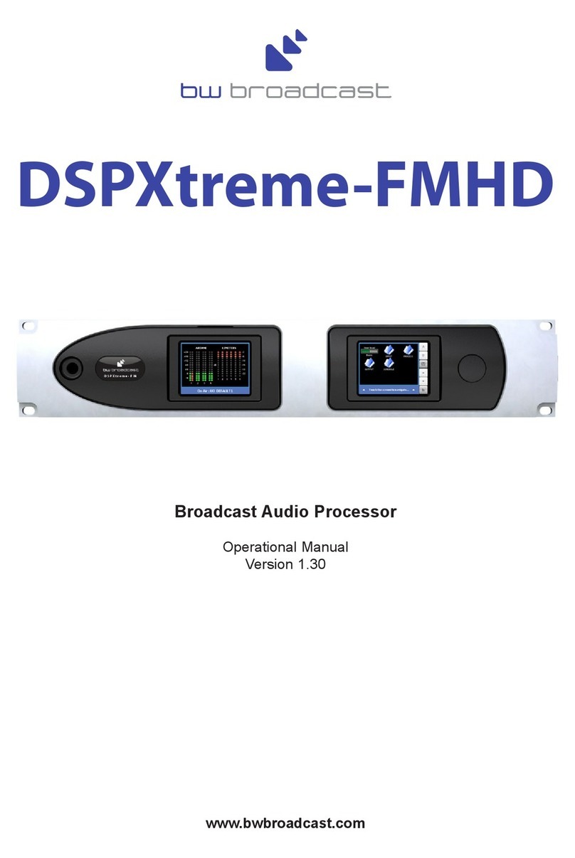
BW Broadcast DSPX-FM Quick start guide

DSPX-FM
Broadcast Audio Processor
Operational Manual
Version 3.20
www.bwbroadcast.com

Table Of Contents
2
Table Of Contents
Warranty 3
Safety 4
Forward 6
Introduction to the DSPX 7
DSPX connections 8
DSPX meters 9
Status LEDS 9
Quickstart 10
An introduction to audio processing 11
Source material quality 12
Pre-emphasis 12
The DSPX and its processing structure 13
The processing path 13
Processing block diagram 15
The DSPX menu system 16
The Menu stucture 17
Setting up the processing on the DSPX 25
Getting the sound that you want 36
Managing Presets 40
Factory presets 41
Remote control of the DSPX 43
Remote trigger port 50
Security code lock 51
Clock based control 52
Specifications 53
USB VCP driver installation Appendix A
Preset Sheet Appendix B

Warranty
3
BW Broadcast warrants the mechanical and electronic components of this product to be free of defects in
material and workmanship for a period of two (2) years from the original date of purchase, in accordance with
the warranty regulations described below. If the product shows any defects within the specified warranty period
that are not due to normal wear and tear and/or improper handling by the user, BW Broadcast shall, at its sole
discretion, either repair or replace the product. If the unit has a manufacturers fault within twenty eight (28) days
then BW Broadcast will pay the freight at their discretion.
If the warranty claim proves to be justified, the product will be returned to the user freight prepaid. Warranty
claims other than those indicated above are expressly excluded.
Return authorisation number
To obtain warranty service, the buyer (or his authorized dealer) must call BW Broadcast during normal business
hours BEFORE returning the product. All inquiries must be accompanied by a description of the problem. BW
Broadcast will then issue a return authorization number.
Subsequently, the product must be returned in its original shipping carton, together with the return authorization
number to the address indicated by BW Broadcast. Shipments without freight prepaid will not be accepted.
Warranty regulations
Warranty services will be furnished only if the product is accompanied by a copy of the original retail dealer’s
invoice. Any product deemed eligible for repair or replacement by BW Broadcast under the terms of this
warranty will be repaired or replaced within 30 days of receipt of the product at BW Broadcast.
If the product needs to be modified or adapted in order to comply with applicable technical or safety standards
on a national or local level, in any country which is not the country for which the product was originally
developed and manufactured, this modification/adaptation shall not be considered a defect in materials or
workmanship. The warranty does not cover any such modification/adaptation, irrespective of whether it was
carried out properly or not. Under the terms of this warranty, BW Broadcast shall not be held responsible for any
cost resulting from such a modification/adaptation.
Free inspections and maintenance/repair work are expressly excluded from this warranty, in particular, if caused
by improper handling of the product by the user. This also applies to defects caused by normal wear and tear, in
particular, of faders, potentiometers, keys/buttons and similar parts.
Damages/defects caused by the following conditions are not covered by this warranty:
Misuse, neglect or failure to operate the unit in compliance with the instructions given in BW Broadcast user
or service manuals. Connection or operation of the unit in any way that does not comply with the technical
or safety regulations applicable in the country where the product is used. Damages/defects caused by force
majeure or any other condition that is beyond the control of BW Broadcast. Any repair or opening of the unit
carried out by unauthorized personnel (user included) will void the warranty.
If an inspection of the product by BW Broadcast shows that the defect in question is not covered by the
warranty, the inspection costs are payable by the customer.
Products which do not meet the terms of this warranty will be repaired exclusively at the buyer’s expense. BW
Broadcast will inform the buyer of any such circumstance. If the buyer fails to submit a written repair order
within 6 weeks after notification, BW Broadcast will return the unit C.O.D. with a separate invoice for freight and
packing. Such costs will also be invoiced separately when the buyer has sent in a written repair order.
Warranty transferability
This warranty is extended exclusively to the original buyer (customer of retail dealer) and is not transferable to
anyone who may subsequently purchase this product. No other person (retail dealer, etc.) shall be entitled to
give any warranty promise on behalf of BW Broadcast.
Claims for damages
Failure of BW Broadcast to provide proper warranty service shall not entitle the buyer to claim (consequential)
damages. In no event shall the liability of BW Broadcast exceed the invoiced value of the product.
Other warranty rights and national law
This warranty does not exclude or limit the buyer’s statutory rights provided by national law, in particular, any
such rights against the seller that arise from a legally effective purchase contract. The warranty regulations
mentioned herein are applicable unless they constitute an infringement of national warranty law.
WARRANTY

BW Broadcast Technical Manual Page 4
Safety Instructions
DETAILED SAFETY INSTRUCTIONS:
All the safety and operation instructions should be read before the appliance is operated.
Retain Instructions:
The safety and operating instructions should be retained for future reference.
Heed Warnings:
All warnings on the appliance and in the operating instructions should be adhered to.
Follow instructions:
All operation and user instructions should be followed.
Water and Moisture:
The appliance should not be used near water (e.g. near a bathtub, washbowl, kitchen sink, laundry tub, in a
wet basement, or near a swimming pool etc.).
The appliance should not be exposed to dripping or splashing and objects filled with liquids should not be
placed on the appliance.
Ventilation:
The appliance should be situated so that its location or position does not interfere with its proper ventilation.
For example, the appliance should not be situated on a bed, sofa rug, or similar surface that may block the
ventilation openings, or placed in a built-in installation, such as a bookcase or cabinet that may impede the
flow of air through the ventilation openings.
Heat:
The appliance should be situated away from heat sources such as radiators, heat registers, stoves, or other
appliance (including amplifiers) that produce heat.
Power Source:
The appliance should be connected to a power supply only of the type described in the operating instructions
or as marked on the appliance.
Grounding or Polarization:
Precautions should be taken so that the grounding or polarization means of an appliance is not defeated.
Power-Cord Protection:
Power supply cords should be routed so that they are not likely to be walked on or pinched by items placed
upon or against them, paying particular attention to cords and plugs, convenience receptacles and the point
where they exit from the appliance.
Cleaning:
The appliance should be cleaned only as recommended by the manufacturer.
Non-use Periods:
The power cord of the appliance should be unplugged from the outlet when left unused for a long period of
time.
This symbol, wherever it appears,
alerts you to the presence of
uninsulated dangerous voltage inside
the enclosure—voltage that may be
sufficient to constitute a risk of shock.
This symbol, wherever it appears, alerts
you to important operating and mainte-
nance instructions in the accompanying
literature. Read the manual.
CAUTION: To reduce the risk of electrical shock, do not
remove the cover. No user serviceable parts inside. refer
servicing to qualified personnel.
WARNING: To reduce the risk of fire or electrical shock, do
not expose this appliance to rain or moisture.
1.3 SAFETY INSTRUCTIONS

BW Broadcast Technical Manual Page 5
Safety Instructions
Object and Liquid Entry:
Care should be taken so that objects do not fall and liquids are not spilled into the enclosure through open-
ings.
Damage Requiring Service:
The appliance should be serviced by qualified service personnel when:
- The power supply cord or the plug has been damaged; or
- Objects have fallen, or liquid has been spilled into the appliance; or
- The appliance has been exposed to rain; or
- The appliance does not appear to operate normally or exhibits a marked change in performance; or
- The appliance has been dropped, or the enclosure damaged.
Servicing:
The user should not attempt to service the appliance beyond that is described in the Operating Instructions.
All other servicing should be referred to qualified service personnel.
CE CONFORMANCE: This device complies with the requirements of the EEC Council
Directives: 93/68/EEC (CE Marking); 73/23/EEC (Safety – low voltage directive);
2004/108/EC (electromagnetic compatibility). Conformity is declared to those standards:
EN50081-1, EN50082-1.
WARNING: This equipment generates, uses, and can radiate radio frequency energy.
If not installed and used in accordance with the instructions in this manual it may cause
interference to radio communications. It has been tested and found to comply with the
limits for a Class A computing device (pursuant to subpart J of Part 15 FCC Rules),
designed to provide reasonable protection against such interference when operated in
a commercial environment. Operation of this equipment in a residential area is likely to
cause interference, at which case, the user, at his own expense, will be required to take
whatever measures may be required to correct the interference.
CANADA WARNING: This digital apparatus does not exceed the Class A limits for radio noise emis-
sions set out in the Radio Interference Regulations of the Canadian Department of Communications.
Le present appareil numerique n'emet pas de bruits radioelectriques depassant les limits applicables
aux brouillage radioelectrique edicte par le ministere des Communications de Canada.

Forward
6
FOREwORd
Thank you for your purchase of the DSPX digital audio broadcast processor.
Over the last decade the staff at BW have observed broadcast processors from afar with fascination and intrigue
and shared a keen interest in digital audio processing. In January 2002 we decided on a whim that it was time
to have a go at designing our own digital audio processor. We knew that if we were going to design an audio
processor we had to do it the BW way and make the processor the most cost effective fully featured all-in-one
broadcast processor on the planet. We knew we didn't have the decades of processing experience that the other
manufacturers had but what we did have was a desire to research the project for as long as necessary to get the
job done. We also knew that by combining the research with BW's embedded systems skills and ability to manu-
facture low-cost cutting edge products we would ensure that the DSPX would be a winner. The one aim, to make
an audio processor that offered all of the features found in the other more costly processors but at a fraction of
the price.
Why DSPX? Like most products the concept is conceived, nameless. The name DSPX came about for several
reasons. Firstly the BW team couldn't decide on a name we liked so the concept became DSP processor X. As
the project developed it soon became clear that the processor was to be a processor for all broadcast seasons
and so in true algebraic fashion X represents many things. DSPX was born.
Once again, thank you for your purchase; we hope you enjoy the DSPX!
BW Broadcast Team

Introduction To DSPX
7
INTROdUCTION TOThE dSPX
The BW DSPX is a new generation of digital audio signal processor that can be used to process audio ready for
FM and digital broadcast.
The DSPX is the first UK designed and manufactured multi-band digital broadcast processor. Using the latest
multi-band DSP technology the DSPX offers a versatile and powerful tool in creating a loud punchy on-air pres-
ence.
The DSPX has been designed and built from scratch using a new approach to the design of a digital audio proc-
essor that incorporates the most up to date components. Cutting edge technologies allow the DSPX to produce
similar results to other processors in the market but in a simpler more cost effective way. The advances we have
made have allowed us to pass the savings on to our customers.
What's Under the Lid?
The DSPX is driven by a fast 8 bit micro-controller which controls an array of specialized analogue and digital
circuits: These include 24-bit A/D and D/A converters, analogue level control circuitry, 18 x 24 bit DSP's, an
Ethernet port, a trigger port, 2 x RS232 ports, 200 LEDS (metering), an LCD screen, 2 sample rate converters, a
headphone jack and memory devices to hold the software and firmware.
The Processing Architecture!
After input selection the 24-bit digital audio signal is passed through a wideband AGC processing block to nor-
malize input levels. The output of the AGC feeds the EQ and audio shaping sections before being split into four
bands by linear phase time aligned filters. The four bands are processed by a further four AGC'S before being
fed to dynamic audio limiters on each band. The unique dual processing paths allow simultaneous processing for
FM and digital radio. Look-ahead limiting and distortion cancelling clipping ensures your signal is kept to a strict
maximum while maintaining crystal clear sound. A supersonic sample rate DSP stereo encoder provides MPX
generation with fantastic stereo separation.
The easy to use front panel control system and LED metering display, afford the user with ease of use and
setup.
Comprehensive control of every processing parameter is available to the user both from the front panel and by
remote (computer) control.
At a fraction of the size, weight and price of its rivals, the DSPX is a clear winner.
Dynamic, fresh & innovative...
... The DSPX

Connections
8
LOW HIGH
MIDHMIDL LOW HIGH
MIDHMIDL
WB
LRLRMPX
CLIP CLIPCLIP
GATE
INPUT AGC OUTPUTLIMITERS
REMOTE
AES/EBU
EDIT
0
-3
-6
-9
-12
-15
-18
-21
-24
-27
-30
-33
-2
-4
-6
-8
-10
-12
-14
-16
-18
-20
-22
-24
-2
-4
-6
-8
-10
-12
-14
-16
-18
-20
-22
-24
0
-1
-2
-3
-4
-5
-6
-9
-12
-15
-18
-21
110
100
90
80
70
60
50
40
30
20
10
PILOT
dB
dB
dB
dB %
USB
DSP X
UP
LOAD
SAVE
DSPX
OUTPUT
PROCESS
HOLD
INPUT
HEADPHONE
JACK
METERING USB
PORT
STATUS
LEDS
SOFT
KEYS
CONTROL
KNOB
ANALOGUE
INPUTS
SCA
INPUT
MPX
OUTPUT
PILOT
OUTPUT
SYNC
INPUT
AES / EBU
INPUT
RS232
&
TRIGGER PORT
LAN
PORT
GND
LIFT
MAINS POWER INPUTANALOGUE
OUTPUTS
AES / EBU
OUTPUT
DSPX-FM FRONT AND REAR PANELS
DSPX-FM

Meters And Status LEDs
9
dSPX METERS
The DSPX has 182 LEDS that provide ‘always on’ instant IO and processing metering.
I/O metering
The input meters show the level of the input audio. The meters are ‘hooked in’ to the DSP code after the input
level selection and mode options. The clip LED’s represent the onset of the A/D convertors clip-point and these
LED’s should not light under any circumstances. Adjust the input gain control of the DSPX if they do.
The output meters represent the level in dB below full scale output. This output level is the peak output level of
the processing and has nothing to do with the actual output level set by the analogue and digital output level
options.
The output meters show a smaller dynamic range compared to the input ones. This reflects the smaller dynamic
range of the audio once processed by the DSPX. If we were to have used the same scale as the input metering
we would not see a lot of activity on the LED’s, with all of the LEDS on most of the time.
The multiplex output metering represents the composite outputs peak level. This is a representation of the out-
put in relation to the peak composite level of the processing and not the actual level set by the multiplex output
level control.
The IO meters follows an approximation of the PPM level of the audio waveform while a floating ‘peak hold’ dot
tracks the absolute value of the waveform
G/R metering
The gain reduction meters show the gain reduction and gating status of the main processing blocks. The range
shown is 0dB to -24dB in 2dB steps with the gating and hold LEDS indicating GATE or HOLD ‘active’ when lit.
There is only one meter per stereo channel and the value shown is the largest gain reduction of the left and right
channels. Under normal operation (with a stereo audio feed) this is fine but you may observe strange metering if
the channels are not very balanced in level or you are using the DSPX to process two seperate mono feeds.
STATUS LEdS
The DSPX front panel contains three status LEDS.
REMOTE: Indicates that the DSPX is currently talking to a remote computer. This will flash during
an update.
AES/EBU: Indicates the presence of an AES/EBU signal connected to the digital audio input of the
DSPX.
EDIT: Indicates that you are currently editing a parameter.
LOW HIGH
MIDHMIDL LOW HIGH
MIDHMIDL
WB
LRLRMPX
CLIP CLIPCLIP
GATE
INPUT AGC OUTPUTLIMITERS
REMOTE
AES/EBU
EDIT
0
-3
-6
-9
-12
-15
-18
-21
-24
-27
-30
-33
-2
-4
-6
-8
-10
-12
-14
-16
-18
-20
-22
-24
-2
-4
-6
-8
-10
-12
-14
-16
-18
-20
-22
-24
0
-1
-2
-3
-4
-5
-6
-9
-12
-15
-18
-21
110
100
90
80
70
60
50
40
30
20
10
PILOT
dB
dB
dB
dB %
USB
DSP X
UP
LOAD
SAVE
DSPX
OUTPUT
PROCESS
HOLD
INPUT

Quickstart
10
QUICk START
1. Install the processor into the rack.
2. Connect AC power to the unit, and turn on the power.
3. Connect the analogue and / or digital audio inputs.
4. Select the analogue or digital input as the source of the processing with the 'INPUT SELECTION' parameter
which can be found in the 'INPUT' menu. Apply audio and observe the input meters. For analogue inputs, adjust
the 'INPUT’ menus 'INPUT LEVEL CONTROL' so that the input meters do not clip. We recommend setting the
mixing board or audio source to full level output (even clipping) prior to adjusting this control. This ensures that
the processor's A/D converter will not clip under any conditions.
FM USE:
5. Select the pre-emphasis setting for your region (input menu). 75 µs for USA and 50 µs for Europe.
6. Connect the audio outputs as required and set the output level and de-emphasis settings for the analogue and
digital outputs to match any external links, stereo encoders, or transmitters that require left and right audio inputs
or an AES/EBU input. Make sure the output mode is set to FM for the output in question.
7. If you are using the MPX Output (preferred), navigate to the ‘STEREO’ menu and adjust the ‘MPX OUTPUT
LEVEL’ to match the transmitter (or link device) that follows the processor. Adjust for 100% modulation with
audio.
8. Select a factory preset (see Managing presets).
dR USE (dAB/hd RAdIO/dRM/FMEXTRA/STREAMING):
5. Set the pre-emphasis setting to OFF from the input menu.
6. Connect the audio outputs as required and set the de-emphasis for the analogue and digital outputs to OFF,
MODE to DR and set the output levels for the analogue and digital outputs to match the equipment that the proc-
essor is connected to.
7. Select a factory preset (see Managing presets).
8. Navigate to the look-ahead menu and adjust the SHELF EQ control to suit. This sets the brightness of the DR
outputs sound.
dUAL USE: FM + dAB/hd RAdIO/dRM/FMEXTRA/STREAMING:
5. Select the FM pre-emphasis setting for your region (input menu). 75 µs for USA and 50 µs for Europe.
6. Connect the audio outputs as required and set the de-emphasis for the analogue and digital outputs to OFF,
MODE to DR and set the output levels for the analogue and/or digital outputs to match the DR equipment that
the processor is connected to (EG: codec/computer).
7. If you are using the MPX Output, (preferred) navigate to the ‘STEREO’ menu and adjust the MPX ‘LEVEL’
Output to match the transmitter (or link device) that follows the processor. If one of the analogue or digital out-
puts needs to feed another piece of equipment that cant take a composite MPX input then make sure you select
FM mode for that output with the appropriate de-emphasis setting to match the corresponding piece of a equip-
ment in the FM chain.
8. Select a factory preset (see Managing presets).
9. Navigate to the look-ahead menu and adjust the SHELF EQ control to suit. This sets the brightness of the DR
outputs sound.
NOTE: The front panel headphone jack connects to the analogue outputs so the sound may be excessively
bright if pre-emphasis is engaged and de-emphasis on the analogue outputs is set to off.

Introduction To Audio Processing
11
INTROdUCTION TOAUdIO PROCESSING
Most audio processors use a combination of compression, limiting and clipping to 'funnel' the dynamic range
down, reducing the peak to average ratio in each stage. A cascaded arrangement of compressor, limiter and
clipper produces the best results. The first stage of processing usually operates in a slow manner, the process-
ing getting progressively faster and more aggressive as the audio passes through the chain. The instantaneous
peak clipper or look-ahead limiter is the final stage of the chain and sets the final peak level.
The images below illustrate a section of audio as it passes through a typical audio processor.
The first image to the right is an unprocessed section of audio.
The images that follow represent compression of the input wave-
form, followed by limiting and then finally peak clipping.
Compression
Compression reduces the dynamic range of the audio waveform
slowly in a manner similar to a trained operator riding the gain.
Compression is usually performed on the RMS level of the audio
waveform and the ratio of compression is usually adjustable.
Compression is usually gated to prevent gain riding and suck-up
of noise during silence or quiet periods.
Limiting
Limiting is a faster form of compression that employs faster time
constants and higher ratios to produce a denser sound while
controlling peaks based upon the peak level of the audio wave-
form. Excessive limiting can create a busier packed wall of sound
effect.
Clipping
Clipping the audio waveform will not produce any audible side
effects if performed in moderation. Excessive clipping will pro-
duce a form of distortion that produces a tearing or ripping
sound. Clipping can also be used as an effective method of high
frequency peak control when used in conjunction with distortion
controlling filtering.
Look-ahead limiting
Often used instead of a clipper in systems that feed bit rate reducing audio codecs, look-ahead limiting exam-
ines the audio waveform and prepares a gain control signal in advance of the delayed audio waveform arriving.
This prevents overshoots while minimising distortion. A look-ahead limiter behaves in the same way as a soft
clipper. Competent look-ahead limiters will usually be of the multi-band variety.

Source Quality And Pre-emphasis
12
SOURCE MATERIAL QUALITY
The DSPX has the ability to substantially improve the quality of your ON-AIR broadcast. However the DSPX can
only work with what you provide it. The best performance will be obtained when the DSPX is fed with very clean
source material. After dynamic multi-band re-equalisation is performed poor quality source material will sound
poorer when processed with the DSPX.
We strongly advise against the use of MP3's and other compressed audio formats for audio storage. If you must
use compressed audio we advise rates of 256 kbps and higher., but linear formats are always to be preferred.
Compressed audio formats employ frequency masking data reduction techniques to reduce the bit-rate. Through
re-equalisation the DSPX can violate the frequency masking characteristics of the bit reduction process, creating
distortion that was inaudible prior to the DSPX processing.
PRE-EMPhASIS
If you are using the DSPX-FM to process for FM broadcast you will need to enable the pre-emphasis filter in the
DSPX.
Even though your STL or transmitter may contain pre-emphasis we recommend disabling it, letting the DSPX-
FM handle the pre-emphasis for the transmission system. The DSPX-FM uses sophisticated processing meth-
ods to limit the high frequency energy of the pre-emphasis curve while maintaining a 'bright' sound.
Using de-emphasis and then pre-emphasising again will only degrade performance and possibly casue over-
shoots, resulting in lower average deviation.
The exception to the rule is when the DSPX-FM is feeding discrete left and right outs to a compressed audio
STL. Bit rate reduction codec's do not cope with pre-emphasis very gracefully and artifacts will be generated.
The best option in this case is to de-emphasise the output of the DSPX-FM prior to the STL system. At the
transmitter site the pre-emphasis can be enabled in the transmitter to restore the processed signal back to nor-
mal prior to transmission.
The best solution is always to locate the processor at the transmission site. This way overshoots are minimised
and quality is maintained.

The DSPX And It's Processing Structure
13
ThE dSPX ANd ITS PROCESSING STRUCTURE
The DSPX broadcast audio processor can be used for processing audio prior to broadcast on FM and digital
radio services. Digital radio encompasses DAB,HD,IBOC and other radio based broadcasting as well as internet
radio, known also as streaming. The DSPX can also be used effectively for audio post production and mastering,
ideal for giving CD’s that HOT sound. It is also possible to use the DSPX for other audio level control/equaliza-
tion applications such as night clubs and bands. However, this manual will only be referring to the use of the
DSPX for FM and digital radio processing.
Before we discuss the processing structure in full we would like to tell you a little about the final peak limiting
stages of the DSPX. The DSPX employs dual output paths for peak control. Your processing application may
need you to configure the DSPX in a certain way. Selecting the wrong output path and or not configuring the
other settings that affect it may seriously downgrade your audio quality.
The first peak control path is known as 'FM' as it is typically used when processing signals for FM broadcast.
It employs distortion controlled clippers to limit the peaks of the signal. Distortion controlled clipping is the best
method for preserving as much high frequency energy as possible, important when the high frequency loss char-
acteristics of the FM broadcast de-emphasis curve is taking into account.
Distortion controlled clipping produces harmonic distortion which if used moderately can produce a sizzling bright
sound but can result in a ripping or tearing sound if used excessively (overdriven).
The second peak control path is known as 'DR' (digital radio) and is the desired method of peak processing
when the output feeds a codec that employs ‘bit rate reduction compression techniques’. The 'DR' path employs
look-ahead limiting as opposed to clipping. Look-ahead limiting produces less artifacts than conventional clip-
ping, so will reproduce the original audio more accurately with less bits of digital information because it is not
wasting bits encoding non-audible clipping artefacts.
Look-ahead limiting produces less harmonic distortion but produces IM distortion if over driven resulting in a
packed, busy sound.
The DSPX can be configured so that each peak control path can be routed to either of the digital or analogue
outputs. The stereo encoder is always fed with the 'FM' path. One popular configuration for FM radio stations is
to use the DSPX to process their FM broadcast and to have the 'DR' path feed their digital radio service or web
stream, each service optimally processed for that medium. We suggest that digital radio services always use the
'DR' path but you are free to experiment with both options.
ThE PROCESSING PATh
Input selection and conditioning
The DSPX offers the user input selection, gain control and a selection from a range of stereo/mono options.
The audio is then routed through defeatable high pass, phase rotating and pre-emphasis filters.
A silence detector provides automatic primary to secondary input failure switching.
Bass enhancement
The DSPX offers two forms of bass enhancement.
1. A 12dB/Octave shelving filter with up to 12dB of gain.
2. Bass tune control.
3. A peaking filter that can be set to provide up to 6dB of gain on 1 of four frequencies with a choice of 4 Q's.
This can be thought of as a simple bass parametric.
Wideband AGC.
For a transparent input levelling function The DSPX employs an RMS detected AGC stage that has various
hidden (automatic) intelligent controls. Return to platform level and speeds interface to the intelligent silence
gating preventing hunting and suck-up during quiet passages. A sophisticated window gating system prevents
small unnecessary level changes.
Xover
The DSPX employs linear-phase time aligned digital FIR filtering to split the audio spectrum into 4 bands
while maintaining sonic transparency. Two Xover frequencies are selectable for each Xover point.
Multi-band AGC
Like the wideband AGC the DSPX processes each band with RMS based levellers. Each bands gain control
processing function can be configured in different manners to provide different effects. Adjustable ratios, band

The DSPX And It's Processing Structure
14
couplings and complex gating features afford the user with full control of this important re-equalisation stage
of the processor.
Multi-band Limiters
Each band has its own dynamic peak limiter. Multiple time constant based detectors with built in adjustable
hold and delay functions significantly reduce distortion.
Mixer
The four bands are 'virtually' mixed together at this stage. In truth, the four bands have become three. The
three bands are fed off into the two peak processing paths.
Distortion controlled clippers (PEAK CONTROL PATH 1)
The DSPX clipping algorithms peak limit (clip) and linear phase filter the audio in three bands for maximum
distortion control before being fed to the final clipper stages.
Look-ahead limiter (PEAK CONTROL PATH 2)
The DSPX look-ahead limiter is one of the most sophisticated available in a broadcast processor. Processing
is performed in three bands for maximum transparency and clarity. A cut shelving filter is provided to compen-
sate for the effect of pre-emphasis when the DSPX is used to process FM signals at the same time.
Output selection, processing and routing
The DSPX allows the user to select where each processing path is routed to and provides output level con-
trols. A de-emphasis option is provided on both the analogue and digital outputs. The digital output sample
rate can also be configured to a variety of settings.
The analogue output also has one extra path that can be routed to its outputs. This is a lower latency (delay)
path that bypasses the final clipper stages and reduces delay by more than 4mS. This can be used to help
with talent (DJ's) who can not get to grips with the delay of the main processing path. This output if selected
should only be used as a studio monitor signal and should not be used ‘on the air’ as the peak clipping stage
in the monitor processing path is not over-sampled or anti-aliased.
The analog and MPX outputs will be affected by the ITU limiter, if it is engaged. The purpose of this limiter is
to comply with the ITU BS.412 standard. The standard calls for limiting of the power of the composite signal
being broadcast. When activated, the ITU limiter will drastically reduce the loudness of your signal.
Stereo encoder
The DSPX's DSP stereo encoder takes its inputs from the FM path of peak processing. The audio fed to the
stereo encoder does not pass through any de-emphasis circuits. The stereo encoder is highly over-sampled
and offers superb stereo performance. A composite clipping function is provided for those who wish to use it,
as well as a pilot protection filter.

Processing Block diagram
15
ANALOG
DIGITAL
A/D
SRC
AGC
LOW
AGC
MID1
AGC
HIGH
AGC
HPF
INPUT WB AGC MB AGC
LPF
BPF
BPF
HPF
P.R.
BASS
SHELF
BASS
PEAK
PRE
MID2
AGC
LOW
LIM
MID1
LIM
HIGH
LIM
MB LIM
MID2
LIM
LPF
BASS CLIP
BPF
MID CLIP
HPF
HF CLIP
N-1
DELAY
ATTACK
RELEASE
LOOKAHEAD
SOFT
HARD
N-1
DELAY
ATTACK
RELEASE
LOOKAHEAD
N-1
DELAY
ATTACK
RELEASE
N-1
DELAY
ATTACK
RELEASE
LPF
15
19
OUTPUT MPX
PILOT OUT
D/A
MPX
COMP
CLIP
DIGITAL
SRC
DE
ANALOG
D/A
DE
PILOT
SYNC
SCA IN
MPX OUT
DSPX-FM PROCESSING BLOCK DIAGRAM
MON
DR
DR
FM
FM
ITU
LIMIT

Menu System Overview
16
MENU SYSTEM OvERvIEw
This section presents an overview of the four main menus and thier submenus and any parameters that are con-
tained in them.
INPUT: Contains all the controls that affect input selection, level control and signal conditioning.
PROCESS: Contains all the controls that affect the processing.
OUTPUT: Contains all the controls that affect output selection, level control and signal conditioning.
SCHEDULE: Contains all the real time clock controls for switching presets (Dayparting).
SYSTEM: Contains all the system controls (non processing) such as remote control and security.

Menu Structure
17
MENU STRUCTURE
MENU: INPUT
SOURCE
STEREO MODE
ANALOG INPUT LEVEL
RIGHT TRIM
INPUT FAIL SWITCH
HIGH PASS FILTER
PHASE ROTATOR
PRE-EMPHASIS
MENU: PROCESS
MENU: WIDEBAND AGC
DRIVE
ATTACK
DECAY
GATE
RTP LEVEL
RTP SPEED
WINDOW GATING
MENU: ENHANCE
DEEP BASS
BASS TUNE
PEAKING BASS FREQ
PEAKING BASS Q
PEAKING BASS GAIN
MENU: XOVER
B1-2 XOVER
B2-3 XOVER
B3-4 XOVER
B4 LPF
MENU: MULTI-BAND AGC
MENUS: BANDS 1-4
DRIVE
ATTACK
DECAY
GATE
RTP LEVEL
RTP SPEED
WINDOW GATING
GATING TYPE
B1<2 COUPLING
B3>4 COUPLING
L/R COUPLING
MENU: MULTI-BAND LIMITERS
MENUS: BANDS 1-4
DRIVE
THRESHOLD
PEAK ATTACK
PEAK DECAY
AVERAGE ATTACK
AVERAGE DECAY
HOLD
DELAY
MASTER DRIVE
B1<2 COUPLING
B2<3 COUPLING
B2>3 COUPLING
B3>4 COUPLING
L/R COUPLING
LIMITERS RATIO
MENU: MIXERS
BAND1MIX
BAND2MIX
BAND3MIX
BAND4MIX
MENU: LOOKAHEAD LIMITER
DRIVE
SHELF
LOW ATTACK
LOW DECAY
MID ATTACK
MID DECAY
HIGH ATTACK
HIGH DECAY
MENU: CLIPPERS
MULTI-BAND CLIP DRIVE
BASS CLIP LEVEL
BASS CLIP TYPE
MID CLIP LEVEL
HF CLIP LEVEL
HF CLIPPING
MAIN CLIP DRIVE
COMPOSITE CLIPPER
ADVANCED:
DYNAMIC MB CLIPPING
MAIN CLIP FINESSE
OVERSHOOT CONTROL
MAIN CLIP TYPE
ITU LIMITER
MENU: OUTPUT
MENU: ANALOG
MODE
OUTPUT LEVEL
DE-EMPHASIS
MENU: DIGITAL
MODE
OUTPUT LEVEL
SAMPLE RATE
DE-EMPHASIS
MENU: STEREO
LEVEL
PILOT LEVEL
PILOT PROTECTION
ITU LIMITER
PILOT OUTPUT
MENU: HEADPHONE
LEVEL
MENU: SCHEDULE (X) REPRESENTS 0-7
TIME
DAYPARTING ON/OFF
DAYPARTS 1-4
DP(X) ON/OFF
DP(X) START TIME
DP(X) TIME ON (LENGTH)
DAYPARTS 5-8
DP(X) ON/OFF
DP(X) START TIME
DP(X) TIME ON (LENGTH)
MENU: SYSTEM
LCD CONTRAST
LED CONTRAST
TRIGGER PORT
CODE LOCK
OUTPUT LOCK
REMOTE SOURCE
MENU: LAN CONFIG
IP
DG (DEFAULT GATEWAY)
SM (SUBNET)
MA1 (MAC ADDRESS PART1)
MA2 (MAC ADDRESS PART2)
PORT
MENU: ABOUT
VERSION
CONCEPT
HARDWARE
CTRL SYS.
REMOTE APP
PROCESSING
BOOTLOAD

Processing Parameters
18
PROCESSING PARAMETERS
The 'INPUT' menu contains all of the options and parameters relating to the control and conditioning of
the audio inputs.
'SOURCE' This parameter allows you to select the between the analog and digital inputs as the source for
the processing.
'INPUT MODE' This parameter allows you to select different mono options as well as the default Stereo
option. There is also the ability to swap the left/right channels.
'ANALOGUE INPUT A/D CLIP LEVEL' Allows you to set the analogue input level with reference to the
DSPX's A/D converter. This would normally be set to +24dBu if driving the DSPX from professional audio
equipment. This would translate to the wideband AGC being driven to 12dB gain reduction by a 0VU (+4dBu)
audio signal. Make sure that the input audio meters NEVER show clipping under any conditions.
'RIGHT TRIM' This parameter allows you to adjust the right channels gain in small increments to BALANCE
out any small gain discrepancies between the left and right channels. The range is +/- 3dB
'INPUT FAIL SWITCH' This parameter allows you to turn on the silence detection system and specify a
silence time. When enabled this parameter will switch the input source from the primary to the secondary
source when a predetermined length of silence occurs.
'HIGH PASS FILTER' This parameter allows you to select from a variety of high pass filters. You can select
from 20Hz, 30Hz, 40Hz, 50Hz and 60Hz. You also have the ability to bypass the high pass filter with the
'OFF option. The high pass filter can be used to reduce rumble on vinyl or can be effective in removing low
frequency energy that could otherwise cause carrier shift (AFC LOOP) problems in older FM transmitters.
We suggest you leave the high pass filter off unless you have a reason to turn it on.
'PHASE ROTATOR' This parameter if enabled will help to reduce vocal distortion in aggressive presets by
reducing asymmetry in the voice which would otherwise put more workload on the clipping stages. We rec-
ommend enabling this option if you want competitive loudness; otherwise leave it off as the phase rotation
process does colour the sound slightly, although this coloration is often used for artistic effect.
'PRE-EMPHASIS' This parameter allows you to activate pre-emphasis when the DSPX is being used to
process for FM broadcast. The available options are 50 µS, 75 µS and OFF
The 'PROCESS' menu allows access to all of the processing blocks that make up the DSPX. There are
only sub-menus inside the 'PROCESS' menu. The sub menus are laid out in the same configuration as
the signal path through the DSPX.
'WIDEBAND AGC'
The wideband AGC in the DSPX like any automatic gain control device is designed to correct input level
fluctuations and provide a consistent level to the other DSPX processing blocks that follow it. The wideband
AGC in the DSPX is designed to operate in an undetectable, unobtrusive manner similar to a trained opera-
tor controlling a mixing desk. As well as the following user adjustable parameters the wideband AGC incorpo-
rates an assortment of intelligent, adaptive, hidden controls that help keep the gain controlling function of the
AGC as inaudible as possible.
'DRIVE' Controls the drive into the AGC. 0 dB drive corresponds to a gain reduction of 12dB, the mid-
way point, when the input to the DSPX is driven at the nominal 0VU level. The drive can be increased or
decreased by up to 12dB. There probably would be no need to deviate the drive setting from 0 dB under
normal operation.
'ATTACK' Controls the attack rate of the AGC, the time the AGC takes to respond to an increase of input
level. The attack time can be varied between 1 and 10 which corresponds to 100mS to 30S on a semi-
exponential scale.
'DECAY' Controls the release/decay rate of the AGC, the time the AGC takes to respond to a decrease of
input level. The DECAY time can be varied between 1 and 10 which corresponds to 100mS to 30S on a
semi-exponential scale.

Processing Parameters
19
'GATE THRESHOLD' The gate function prevents 'suck-up' of noise during periods of silence or low level
audio. The level can be adjusted to turn on when the input drops to a level from -20dB to -40dB. The
gate can also be switched off or forced on. The gate when turned on will cause the gain reduction to
move towards the level set by the RTR LEVEL control and to move towards that level at the rate set by
the RTR speed control.
'RTR LEVEL' The return to rest level sets where the gain reduction will move towards under GATED con-
ditions. The RTR LEVEL can be set to -4dB, -8dB, -12dB, -16dB or -20dB. There is also an AUTO setting
which continuously modifies the RTR LEVEL based upon a rolling average of the last 30 seconds of gain
reduction prior to the GATED condition occurring.
'RTR SPEED' The return to rest speed modifies the attack and decay rates under GATED conditions.
The rate can be slowed down by factors of 1, 2, 4, 8, 16 and 32. This control can leave the rate unmodi-
fied (setting of 1) or slow it down to the point of being frozen (32)
'WINDOW GATING' A separate gating control from the silence gate, the window gate slows down the
attack and decay rates when the audio waveforms level has not moved outside of a pre-defined window,
set by the window gating control. The window can be set between 1 and 6dB or the gate function can be
disabled by setting the control to OFF. The window gating prevents unnecessary gain control when the
audio waveform is already well defined or having a low peak to average ratio. The window gating also
allows faster rates to be used without the audible effects normally associated with the faster rates.
The wideband AGC can be disabled by setting the RTR LEVEL to a fixed level, usually -12dB and setting
the 'GATE THRESHOLD' to ON. This creates unity gain through the AGC when the wideband AGC drive
control is set to 0 dB
The 'ENHANCE' menu contains the low frequency enhancement filters which are used to provide bass
enhancement and help overcome the bass reduction effect of multi-band compression.
‘DEEP BASS’ A 12dB/octave shelving bass equalizer that provides between 0 and 12dB of bass boost.
Use this control with caution as too much low frequency bass boost can cause loss of mid-bass because
the very low frequency bass, often inaudible on many receivers dominates the gain reduction of the
BAND 1 AGC and limiter. A setting of 6dB is a good compromise and starting point.
'BASS TUNE' Adjusts multiple points in the dynamics control system, allowing you to control the 'flavour'
of the bass.
‘PEAKING BASS EQUALIZER’ A pseudo parametric style bass equalizer control that allows you to
sweet tune the bass. Four frequencies, amplitudes and Q's are provided giving you 64 different bass
curves to select from. Frequencies selectable: 60Hz, 76Hz, 95Hz and 120Hz. Q's selectable: 0.4, 1, 2
and 4. Gains selectable: 0, 1.5dB, 3dB, 4.5dB, 6dB.
The 'XOVERS' in the DSPX are now adjustable and provide the user with another tool in creating their sonic
signature
'B1-2 XOVER' Sets the B1-2 Xover point to either 150Hz or 200Hz
'B2-3 XOVER' Sets the B2-3 Xover point to either 720Hz or 1000Hz
'B3-4 XOVER' Sets the B3-4 Xover point to either 4000Hz or 6000Hz
'B4 LPF' Sets the B4 LPF to either 15000Hz or 20000Hz
The 'MULTI-BAND AGC' is designed to re-equalize the program material and create a consistent tonal bal-
ance while maintaining a consistent output level based on the RMS level of the program material.
'B1-4'
'DRIVE' Controls the drive into the AGC. 0 dB drive corresponds to a gain reduction of 12dB, the
midway point. The drive can be increased or decreased by up to 12dB. You may need to increase the
drive a little as you go up through the bands to compensate for the fact that music has less energy in
the higher frequency spectrum compared to low frequencies.

Processing Parameters
20
'ATTACK' Controls the attack rate of the AGC, The time the AGC takes to respond to an increase of
input level. The attack time can be varied between 1 and 10 which corresponds to 100mS to 30S on
a semi-exponential scale.
'DECAY' Controls the release/decay rate of the AGC, the time the AGC takes to respond to a
decrease of input level. The DECAY time can be varied between 1 and 10 which corresponds to
100mS to 30S on a semi-exponential scale.
'GATE THRESHOLD' The gate function prevents 'suck-up' of noise during periods of silence or low
level audio. The level can be adjusted to turn on when the input drops to a level from -20dB to -40dB.
The gate can also be switched off or forced on. The gate when turned on will cause the gain reduc-
tion to move towards the level set by the RTR LEVEL control and to move towards that level at the
rate set by the RTR speed control.
'RTR LEVEL' The return to rest level sets where the gain reduction will move towards under GATED
conditions. The RTR LEVEL can be set to -4dB, -8dB, -12dB, -16dB or -20dB. There is also an AUTO
setting which continuously modifies the RTR LEVEL based upon a rolling average of the last 30 sec-
onds of gain reduction prior to the GATED condition occurring.
'RTR SPEED' The return to rest speed modifies the attack and decay rates under gated conditions.
The rate can be slowed down by factors of 1, 2, 4, 8, 16 and 32. This control can leave the rate
unmodified (setting of 1) or slow it down to the point of being frozen (32)
'WINDOW GATING' A separate gating control from the silence gate, the window gate slows down
the attack and decay rates when the audio waveforms level has not moved outside of a pre-defined
window, set by the window gating control. The window can be set between 1 and 6dB or the gate
function can be disabled by setting the control to OFF. The window gating prevents unnecessary gain
control when the audio waveform is already well defined or having a low peak to average ratio. The
window gating also allows faster rates to be used without the audible effects normally associated with
the faster rates.
The multi-band AGC bands can be individually disabled by setting the RTR LEVEL to a fixed level,
usually -12dB and setting the 'GATE THRESHOLD' to ON. This creates unity gain through the AGC
when the bands drive control is set to 0 dB. The multi-band AGC can be used as a linear phase EQ
stage whose curve is set by the RTR LEVEL controls
'GATING TYPE' This control allows the user to select whether each of the multi-band AGC’s silence
gates work individually or on a ‘one gates all’ basis. Make sure you know what you are doing before
selecting the combined ‘one gates all’ option as it can cause strange effects to occur if the individual
bands gating thresholds are not set appropriately. You would normally turn off the B1 and B4 gates if
selecting this option to avoid gating in the absence of bass or high frequencies. If in doubt ask BW or
leave this control set to the individual option
'B1<2 COUPLING' This coupling control determines the percentage of B2’s gain control path that is fed
to B1’s gain control path.
'B3<2 COUPLING' This coupling control determines the percentage of B2’s gain control path that is fed
to B3’s gain control path.
'B2<3 COUPLING' This coupling control determines the percentage of B3’s gain control path that is fed
to B2’s gain control path.
'B4<3 COUPLING' This coupling control determines the percentage of B3’s gain control path that is fed
to B4’s gain control path.
The band coupling controls can restrict the ability of the bands to wander excessively, destroying the
original spectral balance of the input program material. Lower couplings allow more re-equalisation to be
performed for a more consistent tonal balance. 30% is a good compromise.
'L/R COUPLING' This coupling control determines the percentage that the left and right channels are
linked. 0% is completely uncoupled and equates to a dual mono processing architecture. 100% coupling
ensures the stereo balance of the input program material is maintained. Less coupling can widen the
stereo image for a ‘FAT’ sound.
Table of contents
Other BW Broadcast Computer Hardware manuals