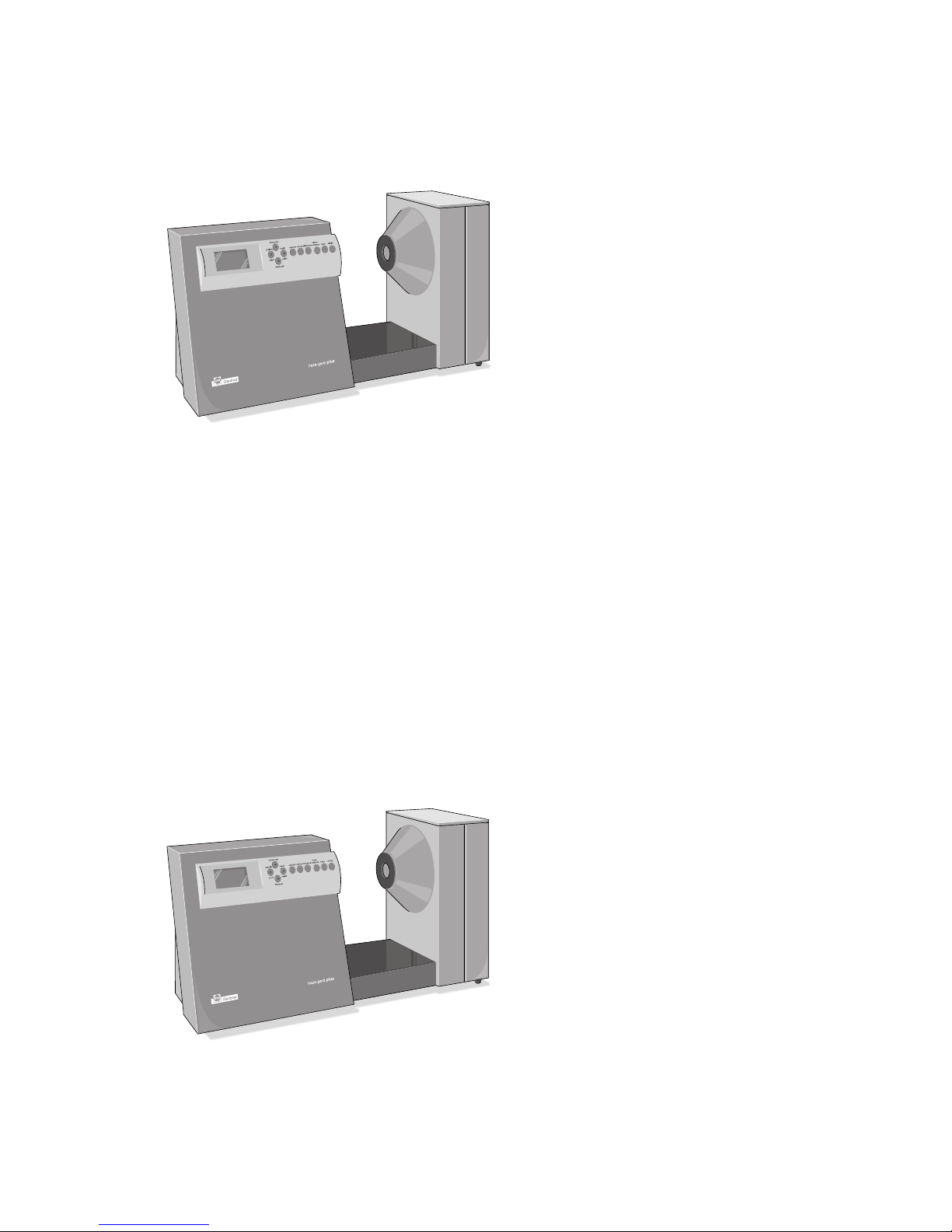
haze-gard plus is a stationary
instrument designed to measure the
appearance of glass and of films,
packaging and parts made of plastic
and other transparent materials.
The specimen surface is illuminated
perpendicularly, and the transmitted
light is measured photoelectrically,
using an integrating sphere
(0°/diffuse geometry). The spectral
sensitivity conforms to CIE standard
spectral value function y, under
standard light C resp. A.
Three parameters:
• total transmittance
• haze
• clarity
permit visual appearance to be
characterized fully and objectively.
haze-gard plus sets new standards
in transparency measurement
instruments. Aside from its speed
and ease of operation, it also offers
the following features:
• pen specimen area for small
and large products
• Automatic calibration and menu-
driven operation
• High accuracy and reliability
thanks to reference-beam optics
• Longterm calibration and self-
diagnosis
• Closed optics and electronics
• Ready to operate immediately
no lengthy warm-up needed
• Foot switch
• Internal statistics functions
• Memory to store readings,
PC interface, printer outlet
haze-gard plus conforms to the
standards ASTM D-1003 and
ASTM D-1044.
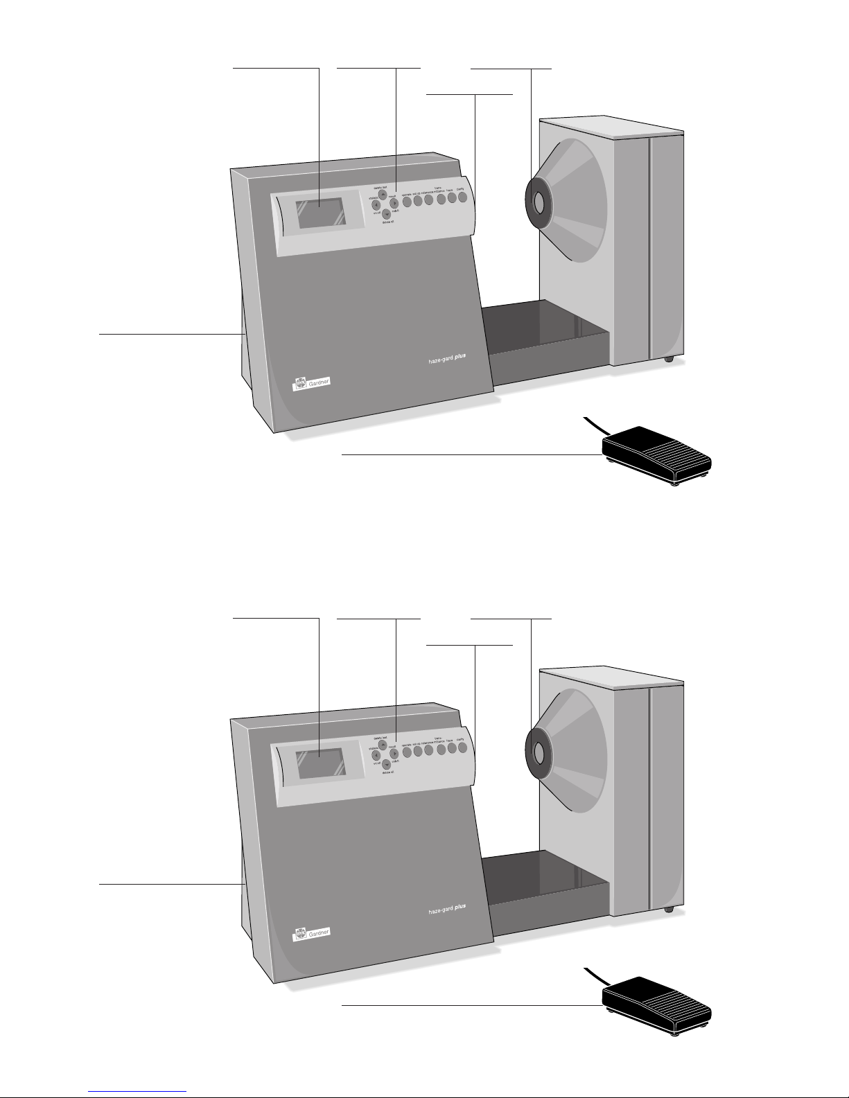
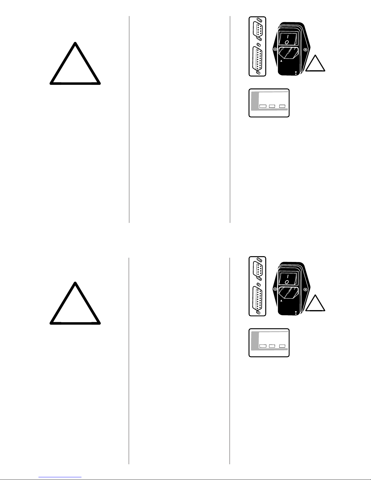
2. System Description
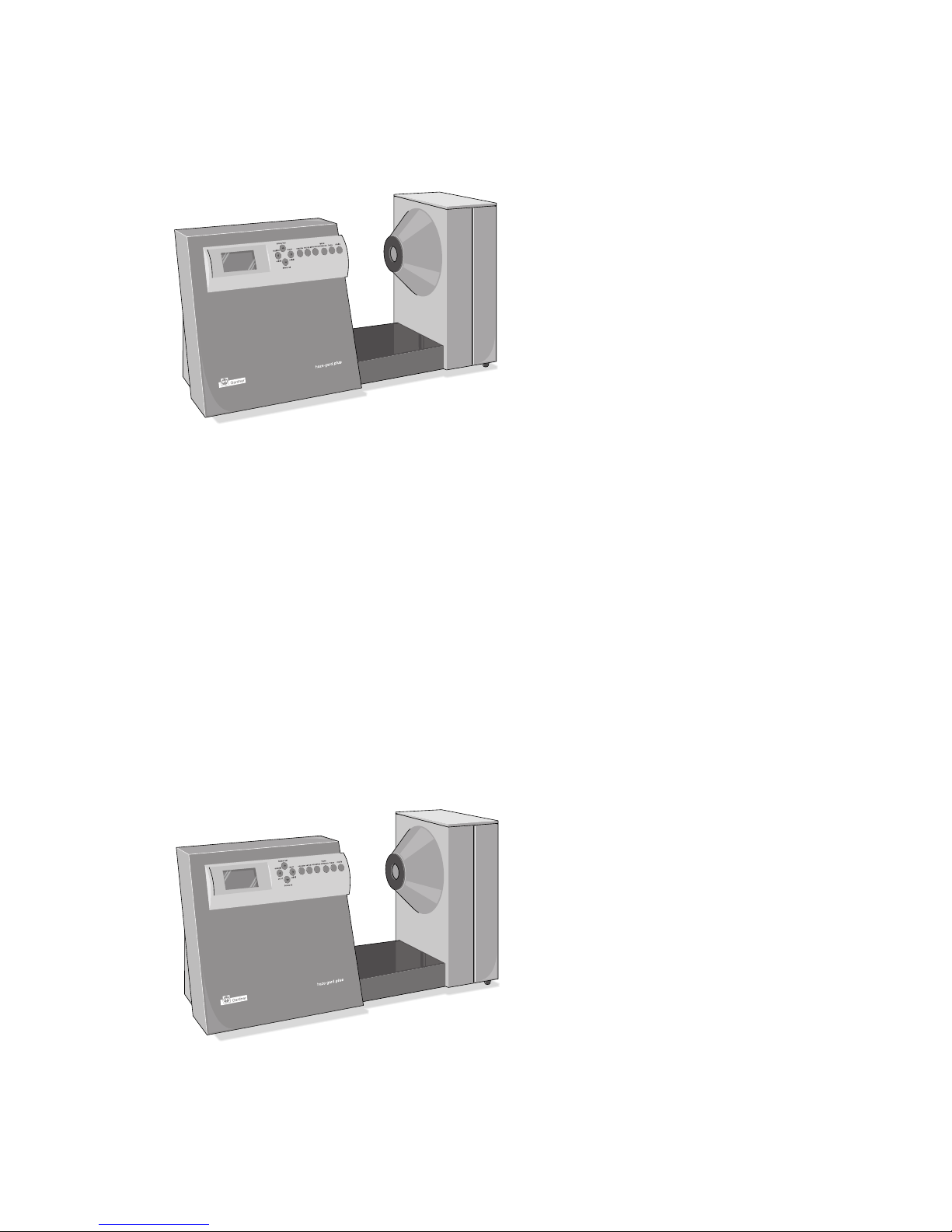
haze-gard plus is a stationary
instrument designed to measure the
appearance of glass and of films,
packaging and parts made of plastic
and other transparent materials.
The specimen surface is illuminated
perpendicularly, and the transmitted
light is measured photoelectrically,
using an integrating sphere
(0°/diffuse geometry). The spectral
sensitivity conforms to CIE standard
spectral value function y, under
standard light C resp. A.
Three parameters:
• total transmittance
• haze
• clarity
permit visual appearance to be
characterized fully and objectively.
haze-gard plus sets new standards
in transparency measurement
instruments. Aside from its speed
and ease of operation, it also offers
the following features:
• pen specimen area for small
and large products
• Automatic calibration and menu-
driven operation
• High accuracy and reliability
thanks to reference-beam optics
• Longterm calibration and self-
diagnosis
• Closed optics and electronics
• Ready to operate immediately
no lengthy warm-up needed
• Foot switch
• Internal statistics functions
• Memory to store readings,
PC interface, printer outlet
haze-gard plus conforms to the
standards ASTM D-1003 and
ASTM D-1044.
2. System Description