C. Bechstein VARIO User manual

C. BECHSTEIN VARIO · INSTALLATION INSTRUCTIONS FOR PIANOS
1
C. BECHSTEIN VARIO duet digital system
Installation Instructions for pianos
Version number of this document: 001
Last updated 16 December 2019
This document is available in the current version
and in other languages as a PDF file.
© 2019, C. Bechstein Digital GmbH, Germany

C. BECHSTEIN VARIO · INSTALLATION INSTRUCTIONS FOR PIANOS
2
INHALT
Required tools 3
Part list digital system 4
Preparing the instrument 7
Removal of the old System 7
Conversion from VARIO Classic to VARIO Duet Digital System 7
Preparation of the current connection (DC) 8
Mounting on the false floor 8
Montage am Rasten 10
Installation of the sensor rail 11
Installation of the sensor rail and preparation of key no. 88 13
Installation of the VARIO Connect base board 15
Positioning the VARIO Connect base board 16
Installing the pedal sensors 17
Mounting for pianos with pedal pivot rods 17
Mounting for pianos without pedal pivot rods 19
Attaching the control modules and
headphone holder 20
Connecting the data cable 23
Initial setup of the software 24
Short overview of the calibration: 24
For assigning an individual Bluetooth identifier (Bluetooth name): 26
Service Contact 26

C. BECHSTEIN VARIO · INSTALLATION INSTRUCTIONS FOR PIANOS
2 3
REQUIRED TOOLS
598
67
4
3
2
1
1. Forstner drill Ø 20.0 mm (0.8“)
2. Countersink
3. Drill Ø 2.5 mm (0.1“)
4. Drilling machine
5. Metre rule
6. Right angle
7. Pencil
8. Chisel
9. Torx screwdriver/ Bit T20

C. BECHSTEIN VARIO · INSTALLATION INSTRUCTIONS FOR PIANOS
4
PART LIST DIGITAL SYSTEM
Cable clamp CBD-00024
VARIO duet Module
black;
white
UE-DUE-01-00001
UE-DUE-02-00001
VARIO silent Module
black;
white
UE-SIL-01-00001
UE-SIL-02-00001
VARIO Display Stand CBD-00025
VARIO Headphones
black;
white
UE-SIL-01-00004
UE-SIL-02-00004
Power supply 19 V
Type C (Euro)
CBD-00028
Connection cable
Type G (UK)
for power supply
CBD-00032
Connection cable
Type A (US)
for power supply
CBD-00033
Clamping sockets for
support frame
CBD-00022

C. BECHSTEIN VARIO · INSTALLATION INSTRUCTIONS FOR PIANOS
4 5
Round-head screw
TX10 3,0 x 10 mm
CBD-00020
Flat ribbon cable
Keysensor rail -
Base board
500 mm (19,7“)
CBD-00023
Pedal sensors with
connection cables
UE-CON-00-00004
Aluminium bracket for
pedal sensors with
mounting tape
UE-CON-00-00005
DC socket for
C. Bechstein
UE-CON-00-00002
DC socket for
W. Hoffmann/
Zimmermann
(angular)
UE-CON-00-00002
Countersunk screw
TX10 3.5 x 15 mm
CBD-00021
Connection Cable
USB-C, 300 mm (11,8“)
black;
white
CBD-00076
CBD-00085
Connection Cable
USB-C, 900 mm (35,4“)
black;
white
CBD-00043
CBD-00054

C. BECHSTEIN VARIO · INSTALLATION INSTRUCTIONS FOR PIANOS
6
Headphone holder
black;
white
UE-SIL-01-00002
UE-SIL-02-00002
Keysensor rail CBD50-7047
Reflector stripes CBD50-0444
Spacer ring CBD50-0598
Base board UE-CON-00-00001

C. BECHSTEIN VARIO · INSTALLATION INSTRUCTIONS FOR PIANOS
6 7
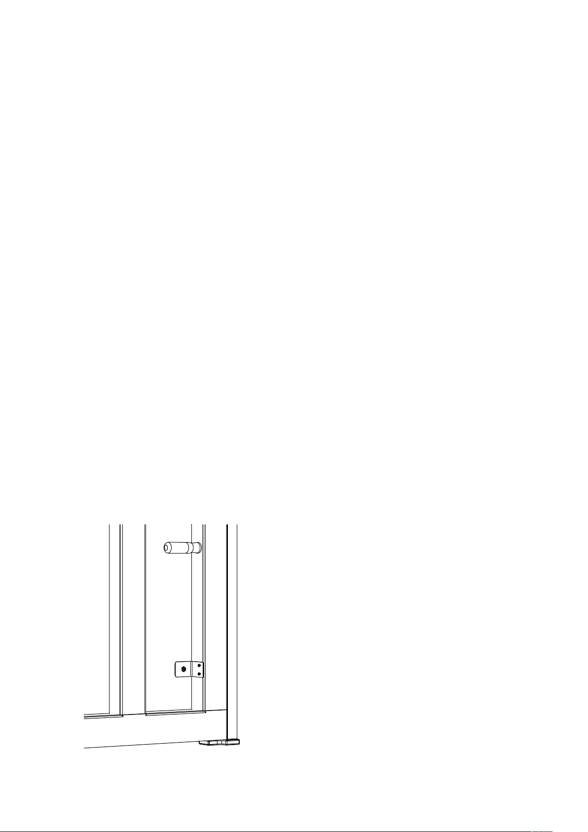
PREPARING THE INSTRUMENT
Before you begin with the installation, you should remove all necessary housing parts,
such as the upper panel, lower panel, the key fall, name-board, cheek-blocks and the
action bolts for fixing the action.
Check the regulation of the piano and adjust it if necessary.
REMOVAL OF THE OLD SYSTEM
If you install the VARIO Duet Digital System in a piano that had another muting system
installed before, remove the previously installed components.
You can also use the VARIO Duet Digital system in conjunction with other manufactu-
rers stop rails. Please note that the pianos playing style only has optimum regulation
with the C. Bechstein VARIO stop rail.
CONVERSION FROM VARIO CLASSIC TO VARIO DUET
DIGITAL SYSTEM
If you remove the previous digital system from C. Bechstein (VARIO Classic), you can
continue to use the stop rail. Leave it in the piano. It is the same as in the current
model. Before calibrating the new system, please check the setting of the stop rail and
adjust it correctly if necessary. The procedure for this can be found in the installation
instructions for the VARIO stop rail. You can also keep the pedal sensors of the VARIO
Classic in the instrument. Replace all other components as described below. Please
note that it is absolutely necessary to use the new power supply with the new DC con-
nection plate.
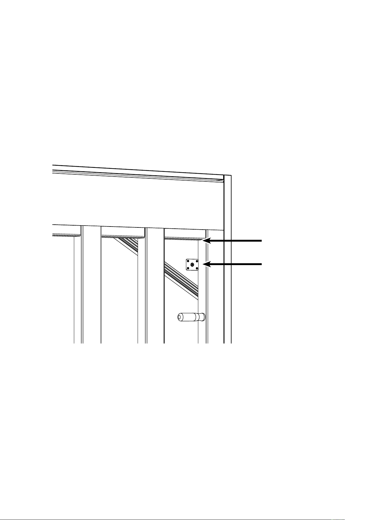
To remove the old distributor boards, please carefully insert a chisel between the board
and the side wall of the piano. Lever the board over a wooden block. Remove the adhe-
sive residue with acetone or benzine.

C. BECHSTEIN VARIO · INSTALLATION INSTRUCTIONS FOR PIANOS
8
PREPARATION OF THE CURRENT CONNECTION (DC)
Mounting on the false floor
(C. Bechstein, Bechstein Academy and Zimmermann)
1. Mark the position of the DC connector on the back of the instrument on the
false floor (bass range).
100 mm (4“)

C. BECHSTEIN VARIO · INSTALLATION INSTRUCTIONS FOR PIANOS
8 9
2. Drill through using a 2.5 mm (1“) drill bit at the marked position.
3. Then drill with the Forstner drill Ø 20 mm (3/4“) approx. up to half.
Then drill from the other side.
Please note that when using these dimensions for pianos with a height of 121 cm (48“)
or more, the left action bracket pivot must be removed in order to be able to drill from
the front. If you want to avoid this, you can also select a different position for the con-
nection.
In any case, please note the position of the carrying handle and the necessary distance
of the socket incl. sheet metal from the back-frame side-brace and soundboard brace.
ATTENTION: Do not drill only from one
side to avoid splintering of the wood!
Screw the DC connection plate to the false floor:
Drilling of the back side up to half with
Ø 20 mm (3/4“)
Drilling the front side

C. BECHSTEIN VARIO · INSTALLATION INSTRUCTIONS FOR PIANOS
10
Montage am Rasten
(W. Hoffmann und Zimmermann)
For pianos without blind floor, as with the W.HOFFMANN series, the angle version must
be used.
The fixing is carried out on the detent bar:
1. Measure 210 mm (8 1/4“) upwards from the upper edge of the back-frame
and mark the position for the hole on the soundboard.
2. Pre-drill with a 2.5 mm drill bit and up to half with a Forstner drill bit
Ø 20 mm (3/4“).
Drill the rest from the other side.
ATTENTION! Do not drill all the way through from one side!

C. BECHSTEIN VARIO · INSTALLATION INSTRUCTIONS FOR PIANOS
10 11
INSTALLATION OF THE SENSOR RAIL
First remove the action and keys from the instrument.
Black out all keys on the side above the sensors. It is enough to blacken the lower third
to the lower edge of the keys.
Thread three to four clamping sockets (CBD-00022) on each side of the support frame
and move them to appropriate positions approximately centered on the fittings between
the keyframe rails. For keyframes without crosspieces, distribute four screws evenly
over the length of the sensor rail on each side.
Make sure that they are positioned correctly on both sides: the sockets can only be
rotated 90° in one direction without any greater effort, so that the countersunk recess
points upwards.

C. BECHSTEIN VARIO · INSTALLATION INSTRUCTIONS FOR PIANOS
12
A minimum distance of the sensor strip within the keyframe results from the size of the
clamping sockets. The strip should be as parallel as possible to the keyframe.
The height of the sensor strip to the keybed is not critical for the later function of the
digital system.
Hint: For instruments with limited space, the sockets can also be omitted on one side so
that a slot in the sensor rail is flush with the keyframe. In order to avoid resonances cau-
sed by vibration, a felt can be placed or glued between the keyframe and the aluminium
rail in such a case.
The horizontal position (left / right) of the sensor rail, must be positioned in such a way
that the sensors (not the white square printed on the circuit boards for each key) are as
centrally as possible under the keys.
Hint: For positioning we recommend to insert the keys 1 and 3. Then move the sensor rail
to the left or right so that the second sensor from the left ( marked A# ) appears in the
middle between these keys.
Both optical sensors for A# are located in the middle between key 1 and 3. Note that
the sensors are slightly offset in the square.
Do not align with the square.

C. BECHSTEIN VARIO · INSTALLATION INSTRUCTIONS FOR PIANOS
12 13
Installation of the sensor rail and preparation of key no. 88
Screw the clamping sockets in central position and discant position using a bit size
TX10. When screwing, please make sure that the clamping sockets are not crushed.
The soft material of the clamping sockets has been selected to allow you to move
the sensor rail later with moderate force.
Then check once again whether the sensor rail has shifted when tightened.
Sensor A# is still perfectly between key 1 and 3? Then remove the two keys and fasten
the two remaining clamping sockets.
For the moment leave all keys removed.
Hint: To prevent damage to the VARIO sensor rail, do not tighten the screws on the
connection rail<>board.

C. BECHSTEIN VARIO · INSTALLATION INSTRUCTIONS FOR PIANOS
14
Place the connection cable (CBD-00023) of the sensor rail.
Use the self-adhesive cable clamps. Make sure that the cable is led along the key block.
If key no. 88 has holes on the bottom, stick the reflector foil (CBD-00019) over it at the
level of the sensors. This is important to ensure a bright and smooth reflective surface
afterwards.
Key no. 88, holes covered with reflector foil
Once all steps are completed, return all keys to the keyframe.
Connecting the ribbon cable. Use cable clamps.

C. BECHSTEIN VARIO · INSTALLATION INSTRUCTIONS FOR PIANOS
14 15
INSTALLATION OF THE VARIO CONNECT BASE BOARD
The VARIO Connect base board (UE-CON-00-00001) is a central component and merges
all connections of the VARIO digital system. It provides the power supply for all compo-
nents and accommodates, among other things, the basic USB and Bluetooth functionality.
In order to accommodate as many instruments as possible in a space-saving manner,
the base board is installed directly on the left-hand side of the piano without surroun-
ding case.
First connect the cables of the following components to the board:
1. DC connection cable (UE-CON-00-00002)
2. USB-C Connection Cable (CBD-00043 Black / CBD-00054 White)
3. Pedal sensors with three-coloured connection cable (UE-CON-00-00004)
4. Cable connection to the sensor rail with grey ribbon cable (CBD-00023)

C. BECHSTEIN VARIO · INSTALLATION INSTRUCTIONS FOR PIANOS
16
Positioning the VARIO Connect base board
The cables must not be bent in the final position of the VARIO Connect base board. The-
refore, first find a suitable position in the instrument. We recommend installation behind
the left keyframe clamp.
The VARIO Connect base board is optimally held in place by magnets, which are atta-
ched directly to wood or lacquer with the help of a double-sided sticker. This mounting
has the advantage that all cables remain easily accessible even in confined spaces. If
necessary, you can easily loosen the VARIO Connect base board and insert it again.
Now remove the protective foil from all magnets and place the VARIO Connect base
board with light pressure on the spot you have selected.
Remove the protective foils from the
magnets.
Press the VARIO Connect base board to the
selected position.

C. BECHSTEIN VARIO · INSTALLATION INSTRUCTIONS FOR PIANOS
16 17
INSTALLING THE PEDAL SENSORS
Mounting for pianos with pedal pivot rods
Note: when retrofitting the former VARIO model (VARIO classic): the pedal sensors and
their cabling are compatible with the VARIO classic and can be retained.
Attach the connection cable of the pedal sensors to the VARIO Connect base board
(UE-CON-00-00001) if not already done.
Provide the surface of the pedals with one reflector strip each at the level of the pedal
sensors. The adhesive surface must be free of dust and grease.
Take the aluminum bracket and the pedal sensor and glue them together. Remove the
protective film of the adhesive point from the sensor and press it firmly into the alumi-
num bracket. Carry out this step for all three pedal sensors.st in den Aluminiumwinkel.
Führen Sie diesen Schritt für alle drei Pedalsensoren durch.
Aluminium bracket and pedal sensor . Pedal Sensor, glued into the bracket.
Reflector strips at pedal sensor level. The distance between pedal sensor and
reflection surface has to be up to
20 mm (3/4“).

C. BECHSTEIN VARIO · INSTALLATION INSTRUCTIONS FOR PIANOS
18
The aluminium brackets with pedal sensors are now attached to the respective pedal
blocks. The pedal sensors and their cables are marked in the following colours:
Right pedal: Red
Middle pedal: Black
Left pedal: White
The distance between pedal sensor and reflection surface has to be 1 to 20 mm and
should be chosen in such a way that the greatest possible difference between the pres-
sed pedal and the rest position can be measured.
Remove the protective foil from the adhesive surface of the aluminium bracket and
press it on firmly.

C. BECHSTEIN VARIO · INSTALLATION INSTRUCTIONS FOR PIANOS
18 19
Mounting for pianos without pedal pivot rods
For pianos without pedal pivot rods (e.g. W.HOFFMANN) the pedal sensors are mounted
on the bottom rail above the pedals. The pedal sensor is glued on the outside (bottom)
of the aluminium bracket.
Pedal sensor, glued outside at the bracket.
Pedal sensor centered above the pedal.

C. BECHSTEIN VARIO · INSTALLATION INSTRUCTIONS FOR PIANOS
20
ATTACHING THE CONTROL MODULES AND
HEADPHONE HOLDER
The VARIO Duet offers two modules with connectors and controls located on the front
of the instrument. The control modules can be mounted in such a way that …
the module fronts are flush with the
keybed, or
the volume control of the larger module
is flush with the keybed so that both
modules disappear discreetly under it.
Other manuals for VARIO
3
Table of contents
Other C. Bechstein Music Equipment manuals