C.ITOH 8510A User manual
DOT
MATRIX
SERIAL
IMPACT
PRINTER
MODEL
8510A
USERS
MANUAL
U.S.A.:
C. ITOH ELECTRONICS, INC.
5301
Beethoven Street,
Los Angeles, Calif.
90066 U.S.A.
{J>c. ITOH &
co.,
LTD.
EUROPE:
5-1, Kita-Aoyama 2-chome,
Minato-ku, Tokyo, Japan
C.P.O.
Box
136 Tokyo 100-91 JAPAN
South-East ASIA:
C. ITOH
&.
CO.,
(WNDON)
LTD.
76 Shoe Lane, C. ITOH
&.
CO.,
(HONG KONG) LTD.
38th Floor
London, EC4A 3JB,
England Connaught Centre
Connaught Road Central
Hong Kong

"This equipment generates and uses radio frequency energy and
if
not
installed and
used properly,
that
is, in strict accordance with the manufacturer's instructions, may
cause interference
to
radio and television reception. It has been type tested and
found
to
comply with the limits for a Class B computing device in accordance with
the specifications in Subpart J
of
Part
15
of
FCC Rules, which are designed
to
provide
reasonable protection against such interference in a residential installation. However,
there is
no
grarantee that interference will
not
occur in a particular installation. If
this equipment does cause interference to radio or television reception, which can
be determined by turning the equipment
off
and on; the user
is
encouraged to try
to
correct the interference by one or more
of
the following measures:
• reorient the receiving antenna
• relocate the computer with respect
to
the receiver
• move the computer away from the receiver
• plug the computer into a different outlet so that computer and receiver are on
different branch circuits
If
necessary, the user should consult the dealer
or
an experienced radio/television
technician for additional suggestions. The user may find the following booklet pre-
pared by
the
Federal Communications Commission helpful:
"How
to
Identify and Resolve Radio-TV Interference Problems". This booklet
is
available from the
US
Government Printing Office, Washington, D.C., 20402, Stock
No. 004-000-00345-4."
(U.S. VERSION ONLY)
"All
of
the features and specifications are
subject
to
change
without
prior notice"

TABLE
OF
CONTENTS
INTRODUCTION
..................................................................
2
PREPARATION
FOR
USE
..........................................................
3
1.
Unpacking Instructions
........................................................
3
2.
Ribbon Cassette Setting . . . . . . . . . . . . . . . . . . . . . . . . . . . . . . . . . . . . . . . . . . . . . . . . . . . . . .
..
5
3. Paper Setting
................................................................
6
4. How
to
Use the Paper Guide Separator
............................................
9
5.
Prjnt Position Adjustment
......................................................
10
6. Gap between Dot Head and
Platen.
. . . . . . . . . . . . . . . . . . . . . . . . . . . . . . . . . . . . . . . . . . . . .
..
11
7.
Power Cord Connection . . . . . . . . . . . . . . . . . . . . . . . . . . . . . . . . . . . . . . . . . . . . . . . . . . . . . .
..
11
OPERATION . . . . . . . . . . . . . . . . . . . . . . . . . . . . . . . . . . . . . . . . . . . . . . . . . . . . . . . . . . . . . . . . . . . .
..
12
1.
Appearance and Nomenclature. . . . . . . . . . . . . . . . . . . . . . . . . . . . . . . . . . . . . . . . . . . . . . . . .
..
12
2. Power Switch and Control Panel
.................................................
13
3.
Operating Switches
............................................................
14
4.
Alert Switches
...............................................................
14
5.
Indicator Lamps
.............................................................
, 14
6.
Self-Test Function
...........
. . . . . . . . . . . . . . . . . . . . . . . . . . . . . . . . . . . . . . . . . . . . . . .
..
15
7.
Dip-Switch Setting
...........................................................
, 16
8. Specification
by
Jumper
................................
: . . . . . . . . . . . . . . . . . . . . .
..
20
9. Connecting the Interface Cable. . . . . . . . . . . . . . . . . . . . . . . . . . . . . . . . . . . . . . . . . . . . . . . . .
..
21
10. Parallel Interface. . . . . . . . . . . . . . . . . . . . . . . . . . . . . . . . . . . . . . . . . . . . . . . . . . . . . . . . . . . .
..
21
11. Serial
Interface.
. . . . . . . . . . . . . . . . . . . . . . . . . . . . . . . . . . . . . . . . . . . . . . . . . . . . . . . . . . . .
..
27
12. Function Codes. . . . . . . . . . . . . . . . . . . . . . . . . . . . . . . . . . . . . . . . . . . . . . . . . . . . . . . . . . . . .
..
41
13. Special Functions
of
the
M8510A
.................................................
46
14. Character Sets/ASCII Tables
.....................................................
54
15. General Operating Notes
........................................................
57
16. Periodic Maintenance
..........................................................
57
17.
Specifications................................................................
60
18. Print
Sample.
. . . . . . . . . . . . . . . . . . . . . . . . . . . . . . . . . . . . . . . . . . . . . . . . . . . . . . . . . . . . . .
..
62
19. Print Paper Specification
........................................................
63
-1-

INTRODUCTION
General Description
The Model 8510A
is
a compact desk-top dot matrix ,serial impact printer used for data communication
terminals, hardcopy
of
CRT displays, peripheral terminals for minicomputers and microcomputers, and
small-sized business systems.
The character format
is
a
dot
matrix
of
7(H) x 9(V),
or
8(H) x 8(V).
Print speed
is
120 characters/second.
Up
to
80 characters can be printed per line in 10 CPI.
Its main features are:
1.
Compact desk-top dot matrix printer
2.
Eighty-column print
3. Light-weight
4.
Low power-consumption
5.
High-quality print
6. Bit image graphics
7.
Graphic symbols
8. Prints in six different languages
9.
High reliability
10. Low cost
-2-

PREPARATION
FOR
USE
1.
Unpacking Instructions
t
Outer
Carton
Power Supply Cord
Fig. 1 Unpacking Instruction (1)
-3-
1.
After opening
outer
carton, take
the
ribbon cassette and power
supply cord out
of
the
pocket
in
the
top
pad.
(Take out the paper guide separator
if
packed together with
the
printer.)
Paper Guide Separator
(Option)
2.
Draw the
top
pad
out
of
the
outer
carton slowly with
both
of
your
hands.
3. Draw
the
printer
out
of
the
outer
carton slowly with
both
of
your
hands.
Caution: Please, do
not
hold
the
knob when drawing
out
the
printer.
(See Fig. 1.)
<9,---
Ribbon Cassette
Packing
Bag
Fig. 2 Unpacking Instruction (2)
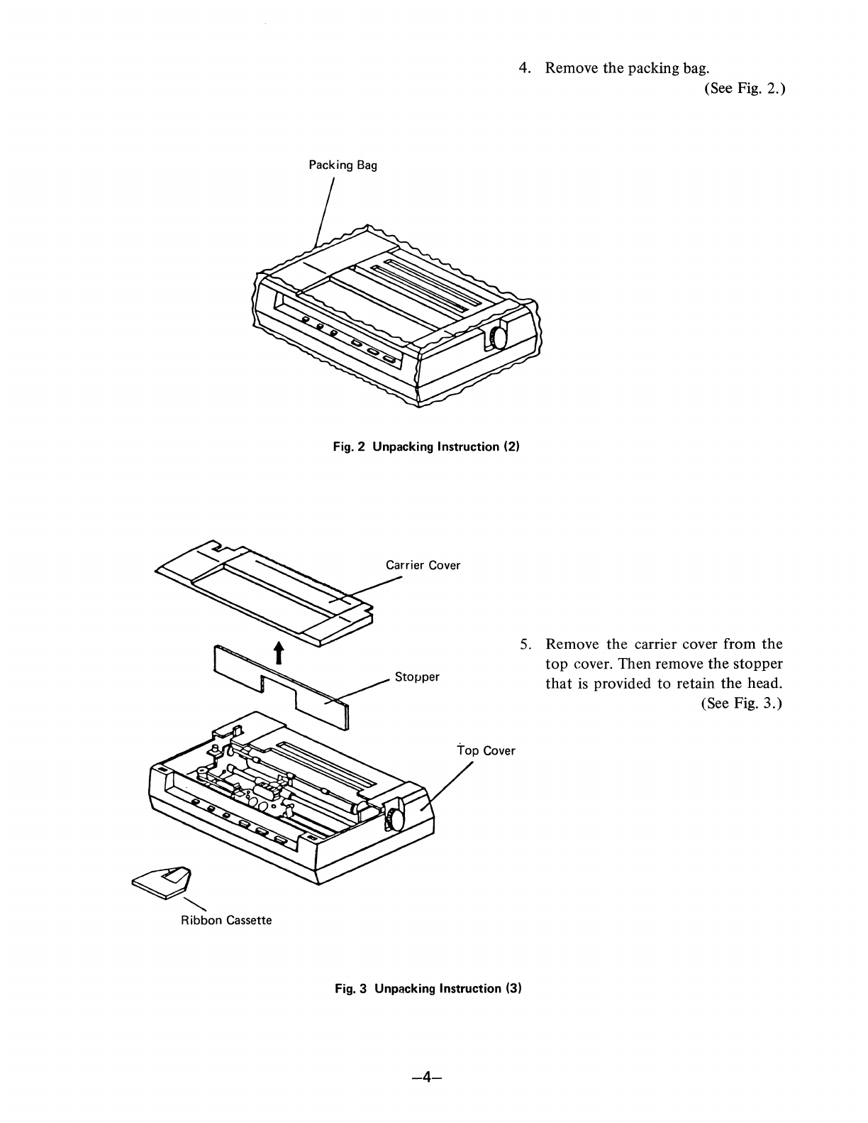
4. Remove
the
packing bag.
(See Fig. 2.)
5.
Remove
the
carrier cover from the
top
cover. Then remove
the
stopper
that
is provided to retain the head.
(See Fig. 3.)
Fig. 3 Unpacking Instruction (3)
-4-
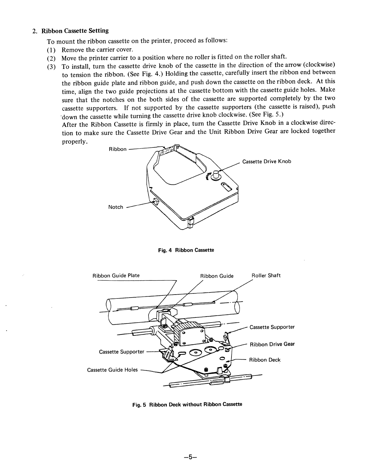
2. Ribbon Cassette Setting
To mount the ribbon cassette
on
the printer, proceed as follows:
(I)
Remove
the
carrier cover.
(2)
Move
the
printer carrier to a position where no roller is fitted
on
the roller shaft.
(3) To install, turn the cassette drive knob
of
the cassette in
the
direction
of
the
arrow (clockwise)
to
tension
the
ribbon. (See Fig. 4.) Holding
the
cassette, carefully insert the ribbon end between
the ribbon guide plate and ribbon guide, and push down
the
cassette
on
the
ribbon deck. At this
time, align
the
two guide projections at
the
cassette
bottom
with the cassette guide holes. Make
sure
that
the
notches on the
both
sides
of
the
cassette are supported completely by
the
two
cassette supporters.
If
not
supported
by
the cassette supporters (the cassette
is
raised), push
·down the cassette while turning the cassette drive knob clockwise. (See Fig. 5.)
After the Ribbon Cassette
is
firmly in place, turn the Cassette Drive Knob
in
a clockwise direc-
tion to make sure
the
Cassette Drive Gear and
the
Unit Ribbon Drive Gear are locked together
properly.
Cassette Drive Knob
Fig. 4 Ribbon Cassette
Ribbon Guide Plate Ribbon Guide Roller Shaft
Cassette Supporter
Ribbon Drive Gear
Cassette Supporter
--"\.,.r.
Cassette Guide Holes
Fig. 5 Ribbon Deck
without
Ribbon Cassette
-5-
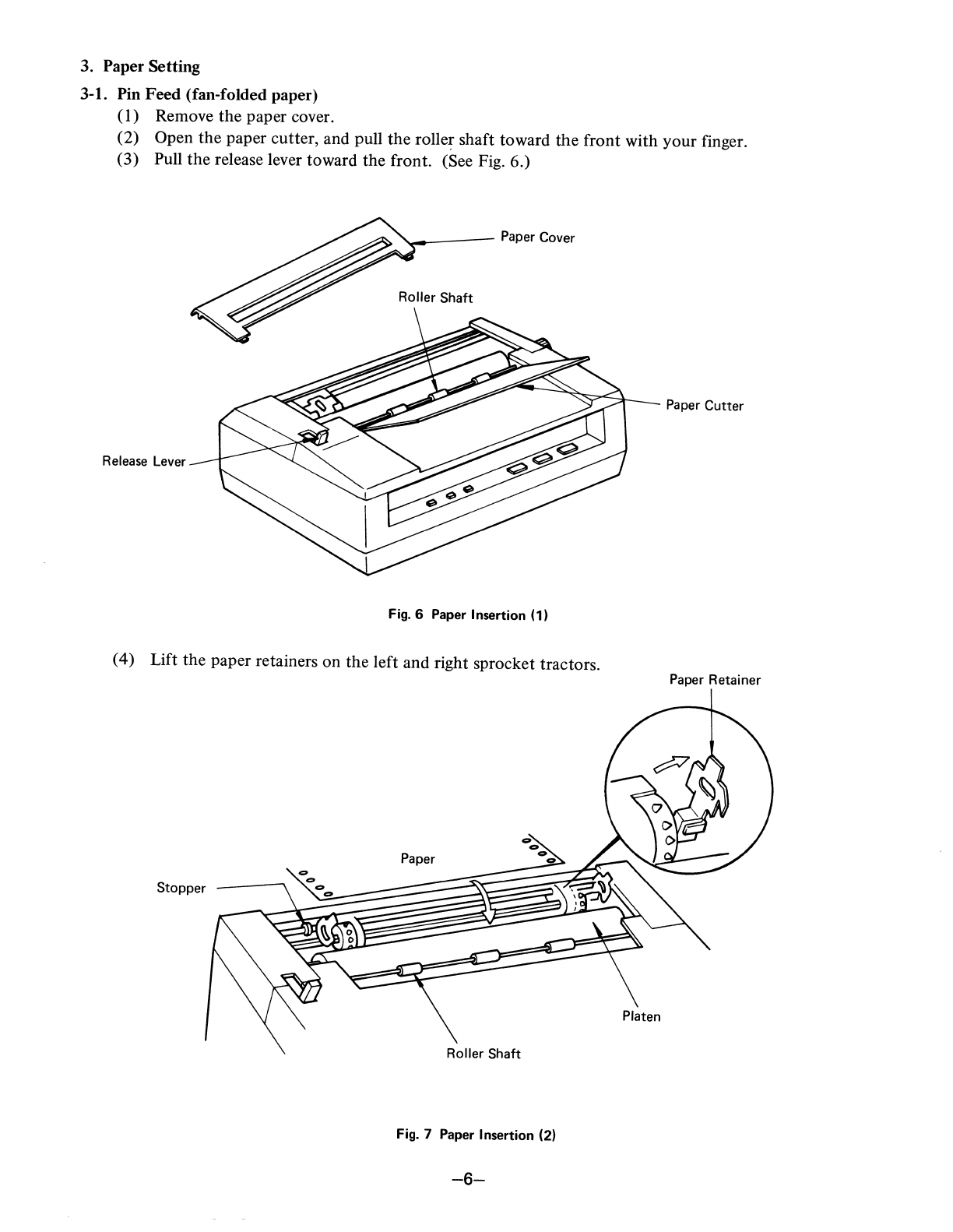
3. Paper Setting
3-1.
Pin
Feed
(fan-folded!>aper)
(1) Remove
the
Paper caver.
(2)
Open the Paper Cutter,
and
PUll the
roller
shaft
tOWard
the
front
With y u
f:
(3)
Pull
the release
le.er
tOWard
the
front.
(See Fig. 6.)
0
r mger.
'--------
Paper
Cover
ROller
Shaft
Release
Lever
Paper
CUtter
Fig. 6
Paper
Insertion
(l)
(4)
Lift the paperretainers
On
the
left
and
right
sprOCket
tractors.
Paper Retainer
Stopper \
'\
....
_
_--..,\.00
......
Paper
ROller
Shaft
Platen
Fig.
7 Paper
Insertion (2)
-6-

(5) Take
the
end
of
the
paper and fit
the
paper sprocket holes
onto
the
right and left sprocket pins.
If
the
paper width necessitates adjusting
the
distance between
the
sprocket
tractor,
push back
the
right
or
left sprocket lever (allowing
the
sprocket tractor(s)
to
move freely) and move
the
sprocket tractor(s) right
or
left
as
needed
to
match
paper width. Then pull
the
sprocket lever(s)
forward
to
lock
the
position
of
the
sprocket
tractor(s). (Refer
to
Fig. 8.)
Sprocket
Lever
Fig. 8 Paper Insertion (3)
(6) Now push down
the
paper clamps
of
the
sprocket tractors.
Turn
the
platen
knob
clockwise,
bringing
the
paper
out
on
the
front side
of
the
platen. Return
the
roller shaft and release lever
to
their previous positions. (Refer
to
Fig.
9.)
Paper
End Platen
Knob
Release Lever
..L~-....f';?~r
Fig. 9 Paper Insertion (4)
(7)
Reposition
the
roller shaft.
(8) Turn
the
release lever
to
the
"pin
feed" position.
-7-

3-2. Frinction Feed (roll paper and sheet paper)
(1)
Open
the
paper cutter, and pull
the
roller shaft toward
the
front.
(2)
Move the head carrier
to
the
left end.
(3)
Turn
the
release lever toward
the
rear.
(4)
Insert
the
paper
into
the
paper inlet
on
the paper cover (behind
the
paper cover for roll paper).
When
the
paper end appears
on
the
platen, set
the
paper properly, turn
the
release lever toward
the front
(to
the "friction feed" position), and reposition
the
roller shaft and paper cutter.
(See Fig. 10.)
Paper
Roller
Shaft
Roller Paper Inlet
-:;;::~~Icl--"..4-_
Paper
Cutter
Release Lever
Fig.
10
-8-
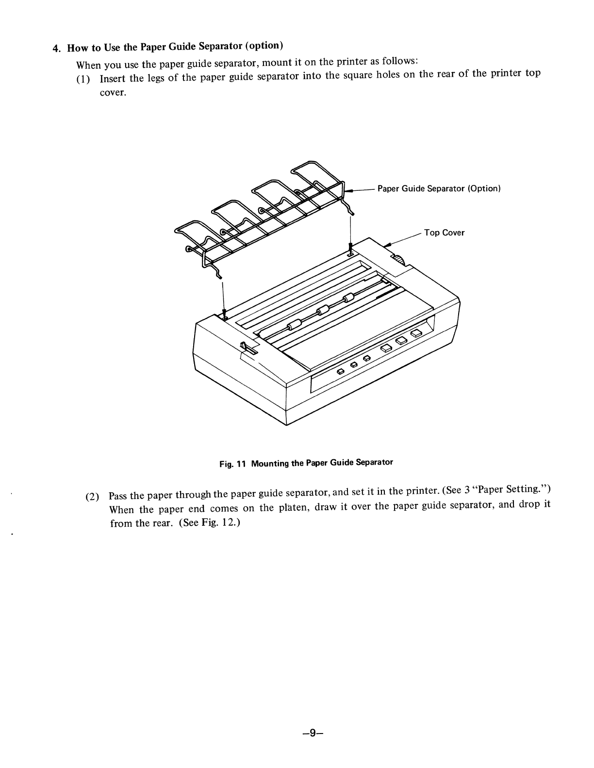
4. How
to
Use the Paper Guide Separator (option)
When
you
use
the
paper guide separator,
mount
it
on
the
printer
as
follows:
(1) Insert
the
legs
of
the
paper guide separator
into
the
square holes
on
the
rear
of
the
printer
top
cover.
1"-"--
Paper Guide Separator (Option)
Top Cover
Fig.
11
Mounting
the
Paper Guide Separator
(2) Pass
the
paper through
the
paper guide separator,
and
set
it
in
the
printer. (See 3 "Paper Setting.")
When
the
paper end comes
on
the
platen, draw
it
over
the
paper guide separator, and drop it
from
the
rear. (See Fig. 12.)
-9-

j
/
Fig.
12 Example of Paper Guide Separator Application
5.
Print Position Adjustment
After
the
paper
is
properly set, turn the right platen knob clockwise
to
adjust the print position.
-10-

6. Gap between
Dot
Head and Platen
The gap between
the
head needle end and the platen is adjustable in 4 steps.
(a) When
the
gap adjusting lever is pushed fully away from you,
the
gap between
the
head needle
end and the platen will
be
0.5
to
0.55. The lever is usually set
at
this position when a single
sheet
of
paper
is
used.
(b) Depending
on
the
number
of
sheets
of
paper, pull
the
gap adjusting lever toward you
to
adjust
the gap.
Head
Platen·to-head
gap
with
adjusting lever
fully
pushed away
from
you.
Head
Adjusting Lever
Fig. 13 Gap Adjustment between
Dot
Head and Platen
7. Power Cord Connection
..
~-""7"C--
Gap
of
0.8
to
0.85
Gap
of
0.7
to
0.75
Gap
of
0.6
to
0.65
Gap
of
0.5
to
0.55
(Single paper)
Connect
the
attached power cord
to
the printer, and insert
the
plug into the
AC
outlet.
-11-
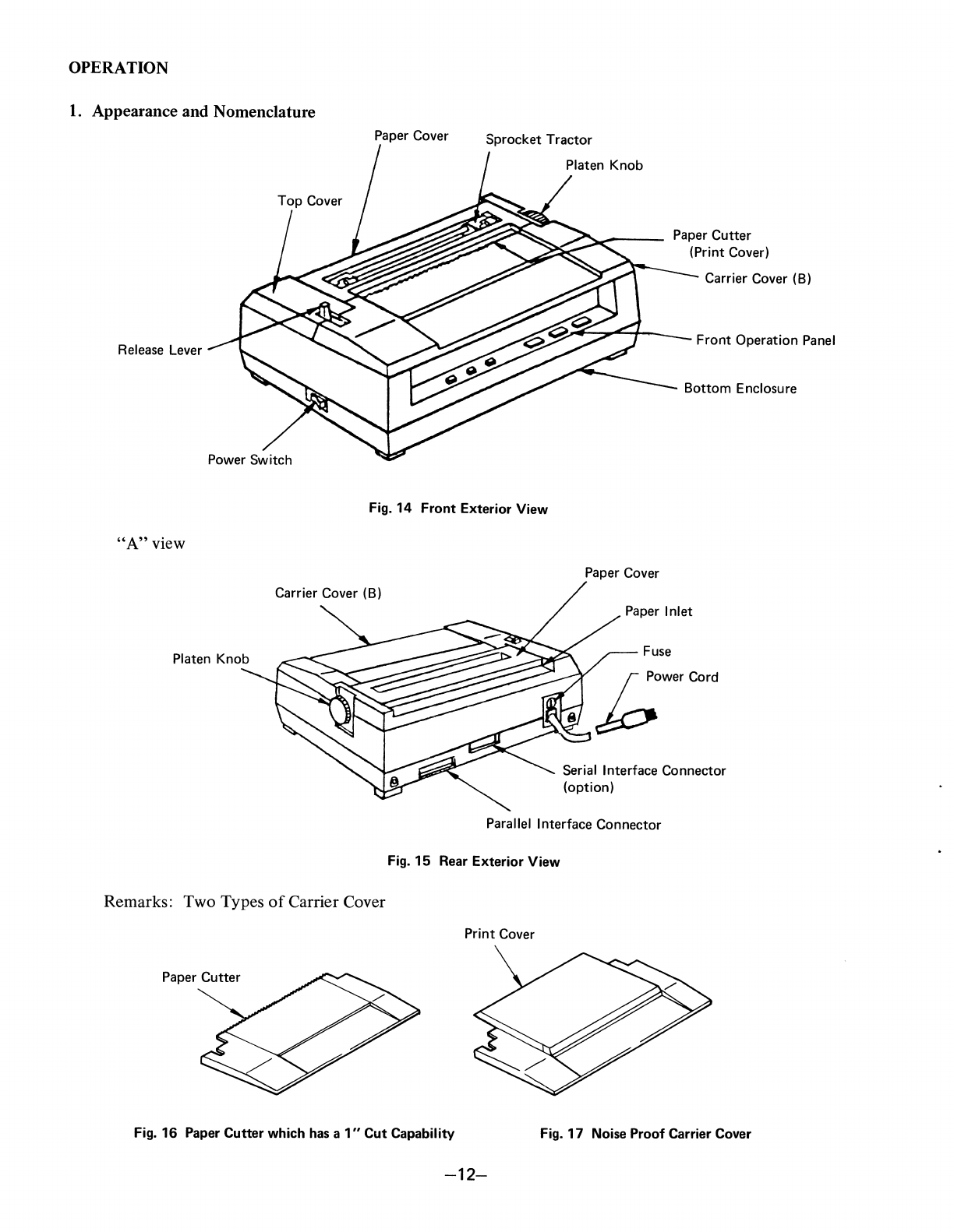
OPERATION
1.
Appearance and Nomenclature
Paper Cover Sprocket Tractor
Paper Cutter
(Print Cover)
Carrier Cover
(B)
Release Lever Front Operation Panel
Bottom Enclosure
Fig.
14
Front
Exterior View
"A"
view
Carrier Cover
(B)
Platen Knob
Remarks: Two Types
of
Carrier Cover
Paper Cutter
Paper Cover
Fuse
~""'''''--1b
Powe, Co,d
Serial Interface Connector
(option)
Parallel Interface Connector
Fig.
15
Rear Exterior View
Print Cover
Fig.
16
Paper Cutter which has a
1"
Cut Capability Fig.
17
Noise Proof Carrier Cover
-12-
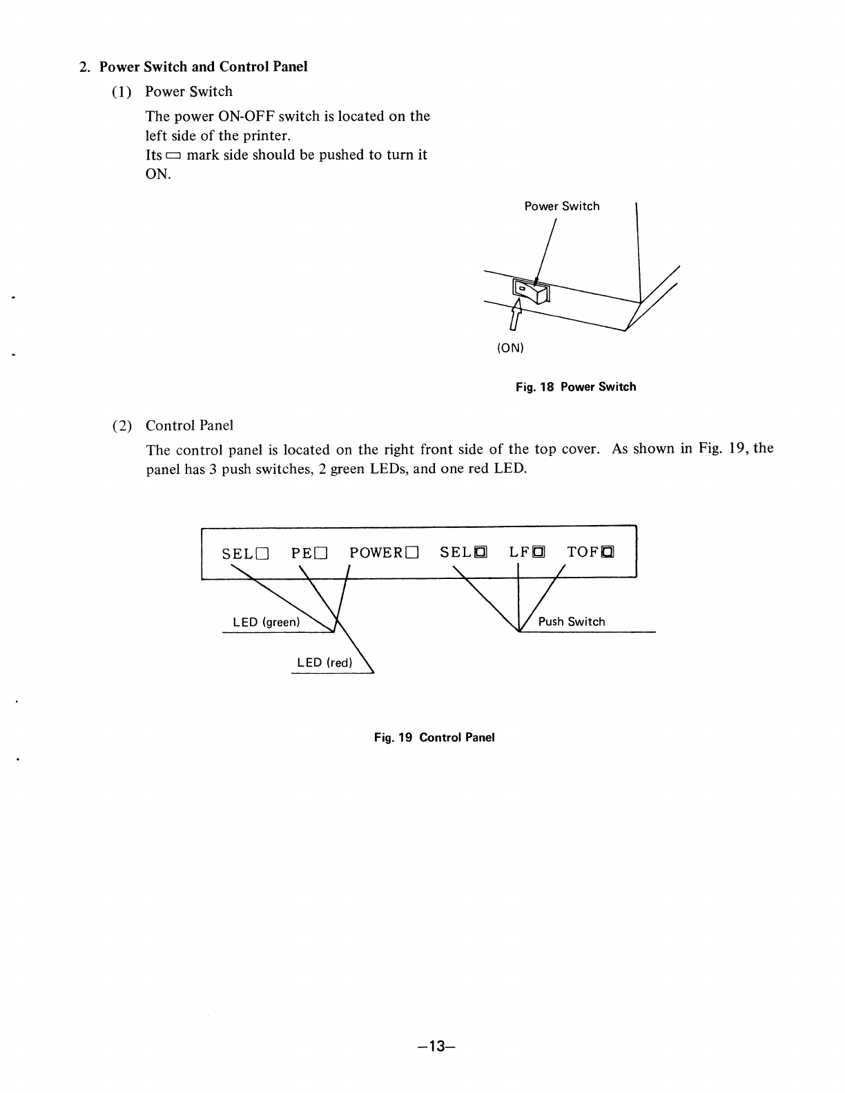
2. Power Switch and Control Panel
(I)
Power Switch
The power ON-OFF switch is located
on
the
left side
of
the
printer.
Its c:::J mark side should be pushed
to
turn
it
ON.
(2) Control Panel
Power Switch
(ON)
Fig.
18
Power Switch
The control panel
is
located
on
the right front side
of
the
top
cover.
As
shown in Fig. 19,
the
panel has 3 push switches, 2 green LEDs, and one red LED.
SELO
PEO
POWERO
SELfJ]
LFfJ]
TOFIl
Fig.
19 Control Panel
-13-
3. Operating Switches
3-1. SEL (Select) Switch
(a) This is a push switch located
on
the
control panel.
(b) SELECT and DESELECT states alternate with every push.
(c) When power
is
applied,
the
printer will become either SELECT
or
DESELECT, depending
on
DIP switch selection. (Refer
to
section 7-10.)
(d) Data transmission and printing
of
data in
the
DATA
BUFFER
can be stopped temporarily.
To
perform this operation, press
the
SEL switch with
the
LF
switch already depressed. To resume
printing and data transmission, press the SEL switch.
3-2.
LF
(Line Feed) Switch
(a) This is a push switch located on the operating panel.
(b) One line feed occurs with every push.
(c) Line feed can be performed only when the printer is in a DESELECT state.
(d) Data transmission and printing
of
data in
the
DATA BUFFER can be stopped temporarily. To
perform this operation, press
the
SEL switch with
the
LF
switch already depressed. To resume
printing and data transmission, press the SEL switch.
3-3.
TOF
(Top
of
Form)
Switch
(a) This is a push switch located on
the
operating panel.
(b) When this switch is pressed, the paper feeds
to
the
next
TOF
position as set in
the
VFU.
(c)
TOF
can be performed only when the
printer
is in a DESELECT state.
4. Alert Switches
4-1. PE (Paper
Empty)
Switch
(a) This is a microswitch installed beneath
the
platen.
(b) When this sensor detects
that
the paper end is near (25
mm
from the end),
the
PE lamp is lit.
The printer enters the DESELECT state, data reception ceases and print operation stops. The
printer
enters a FAULT state.
4-2. Cover Interlock Switch
(a) When
the
top
cover
is
open, printing will stop
and
the printer will
enter
the
DESELECT and
FAULT states.
(b) To resume printer operation, close
the
cover and press
the
SEL switch.
5. Indicator Lamps
The following lamps are located
on
the
control panel.
5-1. SEL Lamp (Green)
This lamp is Iit when
the
printer is in the SELECT state.
5-2. PE Lamp (Red)
This lamp is Iit when
the
PE microswitch is activated.
5-3. Power Lamp (Green)
The lamp is Iit when
the
printer power is on.
-14-

6. Self-Test
Function
M8510A has a Self-Test function
to
check printing operation.
To
activate Self-Test, perform
the
following steps:
(1)
Turn power ON. Check to see
that
the carriage
is
returned
to
the
left home position. Turn
power OFF.
(2) Set the paper.
(3) With the
TOF
button
depressed, turn power ON,
then
release
the
button. The printer will auto-
matically print
the
preprogrammed test pattern, perform line feed, and print again. The Self-
Test function will continue, providing a sample
of
the
print capabilities.
(4) To stop Self-Test,
turn
power OFF.
-15-

7. DIP Switch Setting
DIP switch setting allows various selections
to
be made
as
described below.
DIP
SW-l
and
SW-2
are mounted on the main
PC
board. They are visible
at
right and accessible when
the carrier cover
is
opened.
"ST"
denotes the setting made
at
the time
of
shipment from the factory.
SW1
SW2
&r~/C/t
~
00000000
OPEN III
00000000
OPEN
National Character
Set
TOF-to-TOF
Processing
of
DCl
and
DC3
LF
or
Non-LF when
DATA
BUFFER
is
Full
Print Command
Code
Function
of
CR
Numeric Display
of
0
Selection
of
3K
Buffer or
Single Line Buffer
No Function (OPEN)
L--________
Selection
of
Character Pitch
at Power-On
Selection
of
7-Bit or 8-Bit
Data
SELECT or DESELECT
at
Power-On
L--
____________
Bidirectional Print or
Unidirectional Print
~
7
-6
)
'f
3
2-
Sw \
C-
D
'0
'0
C 0
0 C
~
1 b
~
~
3
2-
Svft2-
0 0 Q 0 0
0 C G
-16-
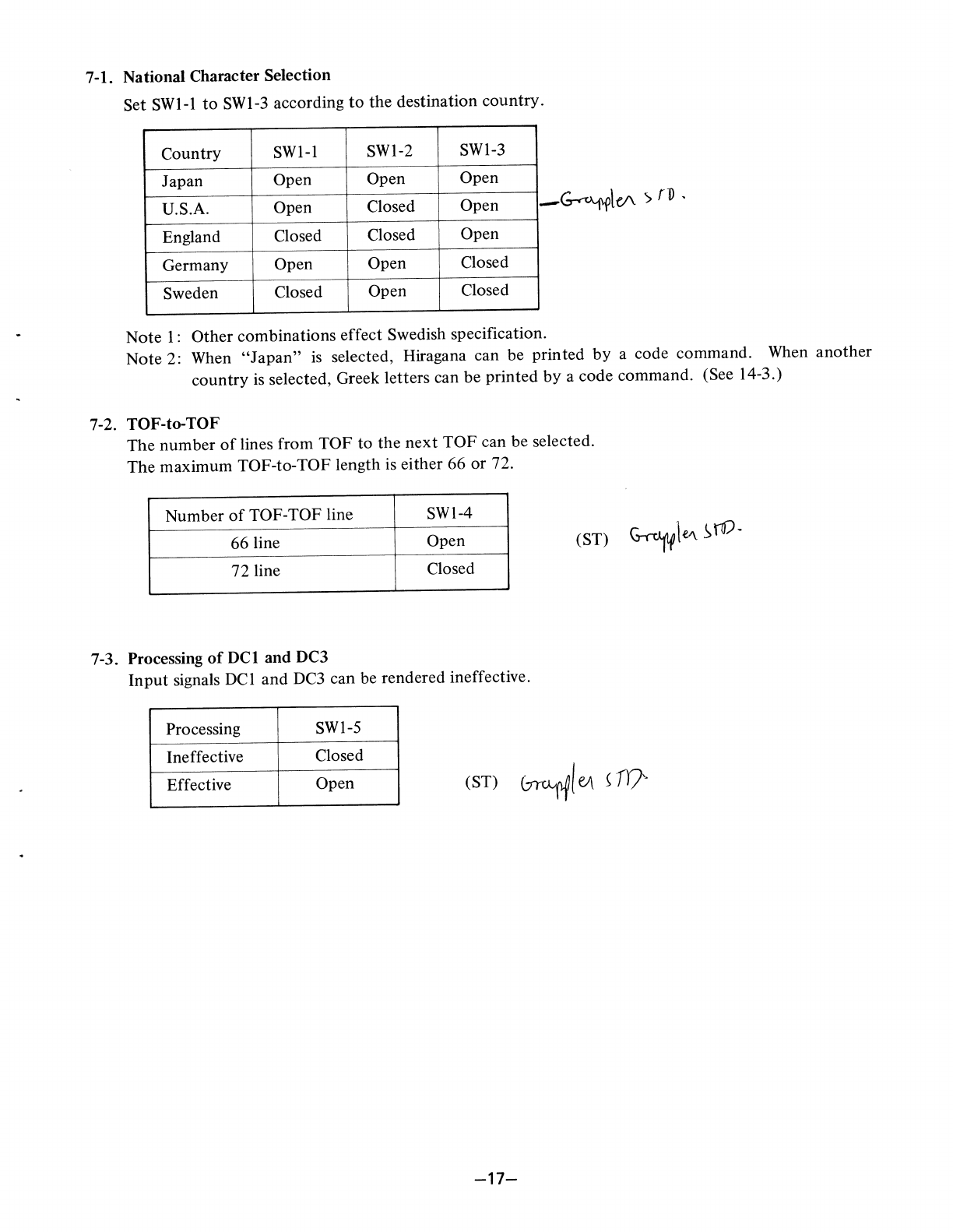
7-1. National Character Selection
Set SWl-l
to
SWl-3 according
to
the destination country.
Country SWl-1 SWl-2 SWl-3
Japan Open Open Open
U.S.A. Open Closed Open
England Closed Closed Open
Germany Open Open Closed
Sweden Closed Open Closed
Note
I:
Other combinations effect Swedish specification.
Note 2: When
"Japan"
is
selected, Hiragana can be printed
by
a code command. When
another
country
is
selected, Greek letters can be printed
by
a code command. (See 14-3.)
7-2. TOF-to-TOF
The number
of
lines from TOF to the next
TOF
can be selected.
The
maximum TOF-to-TOF length is either 66
or
72.
Number
of
TOF-TOF line SWl-4
66 line Open
72 line Closed
7-3. Processing
of
DCI and DC3
Input
signals DCl and
DC3
can be rendered ineffective.
Processing SWl-5
Ineffective Closed
Effective Open (ST)
~I
eJ\
~
Fr}·
-17-

7-4. LF
or
NON-LF when DATA BUFFER
is
Full
When the DATA BUFFER is full, the data will be printed
out
without a print command code. At this
point, one line feed
mayor
may
not
take place, depending
on
the position
of
the DIP switch.
Condition SWI-6
LF Closed
Non-LF Open (ST)
7-5.
Print Command Code
Several command codes in addition
to
CR may serve
as
print command codes. (In incremental print
mode this selection
is
unnecessary because each character
is
printed
as
it
is
received.)
Command Code SWI-7
CR Only Open
CR, LF, VT, FF,
US
Closed
i'--
7-6. Function
of
CR
One line feed
mayor
may
not
take place following a Carriage Return.
Function SWI-S
CR Open (ST)
CR+LF
Closed
7-7. Numeric Display
of
0
The numeral 0 may be printed with or without a slash.
Display
SW2-1
0 Open (ST)
0 Closed
7-S.
Selection
of
Character Pitch
at
Power-On
Characters may be printed 10 CPI
or
proportionally (spacing allowance made depending on the size
of
the character).
These are the options available at Power-On. Other print modes are software selectable. See section
14-2 for details.
Print Mode
SW2-5
10
CPI
character Open (ST)
Proportional character Closed
-18-
Table of contents
Other C.ITOH Printer manuals


