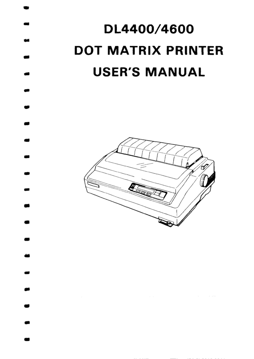
C.ITOH 1550S EP User manual

DOT
MATRIX
SERIAL
IMPACT
PRINTER
MODEL
1550S/SC
EP
USERS
MANUAL
<€P
c.
aTOH
&
co.,
LTD.
e.p.o.
Box
136
Tokyo
100-91
Japan
U.S.A.:
C.ITOH ELECTRONICS, INC.
5301
Beethoven Street,
Los Angeles, Calif.
90066 U.S.A.
EUROPE:
C.ITOH ELECTRONICS CO.,
LTD.
Beacon House 26128
Worple Road, Wimbledon,
London SW19 4EE
United Kingdom
C. ITOH ELECTRONICS CORP.
Toho Seimei Bldg. 27th,
2-15-1
Shibuya, Shibuya-ku,
Tokyo
150
Japan
C.ITOH ELECTRONICS
GmbH
RoBstraBe 96
4000 Dusseldorf 30
West Germany

Thank
you for purchasing the model 1550S/SC EP.
"This equipment generates
and
uses radio frequency energy
and
if
not
installed
and
us-
ed properly,
that
is, in strict accordance with the manufacturer's instructions, may cause
interference to radio
and
television reception.
It
has been type tested
and
found to com-
ply with-the limits for a Class B computing device in accordance with
the
specifications
in
Subpart J
of
Part
·15
of
FCC Rules; which are designed
to
provide reasonable protec-
tionagainst such interference in a residential installation. However, there is no guarantee
that
interference will
not
occur
in
a particular installation.
If
this equipment does cause
interference
to
radio
or
television reception, which can be determined by turning the
equipment
off
and
on, the user
is
encouraged
to
try to correct
the
interference by one
or
more ·of
the
following measures:
• reorient
the
receiving antenna
• relocate
the
computer with respect
to
the
receiver
• move the computer away from the receiver
• plug the computer into a different outlet so
that
computer
and
receiver are
on
clif-
ferent branch circuits
If
necessary, the user should consult the dealer
or
an
experienced radio/televisiontechni-
cian for additional suggestions.
The
user may find the following booklet prepared by
the Federal Communications Commission helpful:
"Howto Identify and Resolve Radio-TV Interference Problems". This booklet is available
from the US Government Printing Office, Washington, D.C., 20402, Stock No.
004-000-00345-4~'
Note:
In
order to comply with the limits for a Class B computing device pursuant to Subpart
J
of
Part
15
of
FCC
Rules, please use the Shield cable for interfacing with
the
host com-
puter. (US. VERSION ONLY)
This equipment is manufactured
to
comply with VDE-871/875. However there is no
guarantee that the fault
wave
to other equipments will
not
occur in a paticular connection.
"All of the features and specifications are
subject to change without prior notice"

TABLE OF CONTENTS
Page
INTRODUCTION
................................................................
1
1.1
Features.
. . . . . . . . . . . . . . . . . . . . . . . . . . . . . . . . . . . . . . . . . . . . . . . . . . . . . . . . . . . .
..
I
1.2 Printer Specifications . . . . . . . . . . . . . . . . . . . . . . . . . . . . . . . . . . . . . . . . . . . . . . . . . . .
..
2
INSTALLATION. . . . . . . . . . . . . . . . . . . . . . . . . . . . . . . . . . . . . . . . . . . . . . . . . . . . . . . . . . . . . . .
..
4
2.1
Unpacking Instmctions
...................................................
4
2.2 Ribbon Cassette Installation. . . . . . . . . . . . . . . . . . . . . . . . . . . . . . . . . . . . . . . . . . . . . .
..
6
2.3 Paper Insertion . . . . . . . . . . . . . . . . . . . . . . . . . . . . . . . . . . . . . . . . . . . . . . . . . . . . . . . . .. 7
2.3.1 Pin Feed (fan-folded paper)
.........................................
7
2.3.2 Friction Feed (roll paper and sheet paper)
..............................
10
2.4
Use
of
the Paper Guide Separator (option) . . . . . . . . . . . . . . . . . . . . . . . . . . . . . . . . . . .
..
11
2.5 Print Position Adjustment
.................................................
12
2.6 Adjustment
of
Gap between Dot Head and Platen . . . . . . . . . . . . . . . . . . . . . . . . . . . . .
..
13
2.7 Power Cord Connection
...................................................
13
OPERATION
....................................................................
14
3.1 Appearance and Nomenclature. . . . . . . . . . . . . . . . . . . . . . . . . . . . . . . . . . . . . . . . . . . .
..
14
3.2 Power Switch and Control Panel
............................................
15
3.3 Operating Switches. . . . . . . . . . . . . . . . . . . . . . . . . . . . . . . . . . . . . . . . . . . . . . . . . . . . .
..
16
3.3.1 SEL (Select) Switch
...............................................
16
3.3.2 LF (Line Feed) Switch
.............................................
16
3.3.3 TOF (Top
of
Form) Switch
.........................................
16
3.4 Alert Switches
..........................................................
16
3.4.1
PE
(Paper Empty) Switch. . . . . . . . . . . . . . . . . . . . . . . . . . . . . . . . . . . . . . . . .
..
16
3.4.2 Cover Interlock Switch. . . . . . . . . . . . . . . . . . . . . . . . . . . . . . . . . . . . . . . . . . .
..
16
3.5 Indicator Lamps . . . . . . . . . . . . . . . . . . . . . . . . . . . . . . . . . . . . . . . . . . . . . . . . . . . . . . .
..
17
3.5.1 SEL Lamp (Green) . . . . . . . . . . . . . . . . . . . . . . . . . . . . . . . . . . . . . . . . . . . . . .
..
17
3.5.2 PE Lamp (Red)
..................................................
17
3.5.3 Power on Lamp (Green)
............................................
17
3.6 Other Functions . . . . . . . . . . . . . . . . . . . . . . . . . . . . . . . . . . . . . . . . . . . . . . . . . . . . . . .
..
17
3.6.1 Self-Test Function
................................................
17
3.6.2 Print Start Conditions
.............................................
17
3.6.3 PE Over Ride Function
............................................
18
3.6.4 Print Stop Function in Case
of
Emergency
..............................
18
3.6.5 Received Data Hexadecimal Print
Out
Function
.........................
18
3.7 DIP Switches Setting
.........................................
,
...........
19
3.8 Connecting the Interface Cable
.............................................
21
3.9 Specification
of
Parallel Interface. . . . . . . . . . . . . . . . . . . . . . . . . . . . . . . . . . . . . . . . . .
..
23
3.10 Parallel Interface Timing Chart
..............................................
23

3.11 Connector Pin Assignment and Descriptions
....................................
24
3.12 Print Modes
.............................................................
27
3.13 Control Codes for Printing
....................................
,
.............
27
3.14 List
of
ESC Commands and Print Samples
......................................
31
3.15 General Operating Notes
...................................................
40
-3.16 Periodic Maintenance
......................................................
40
3.17 Print Paper Specifications. . . . . . . . . . . . . . . . . . . . . . . . . . . . . . . . . . . . . . . . . . . . .
..
. .
..
43
3.17.1
FanfoldComputerForms
............................................
43
3.17.2 Single Sheet Paper
........................................
,
........
46
3.17.3 Roll Paper
.......................................................
47
APPENDIX
1 Specification
of
Color
Print
. . . . . . . . . . . . . . . . . . . . . . . . . . . . . . . . . . . . . . . . . . .
..
48
ii

INTRODUCTION
MODEL l550S/SC EP PRINTER
1.1
Features
The l550S/SC EP
is
a sophisticated compact dot matrix printer which can greatly enhance
the
printout
capability and control flexibility for your computer system.
It
is
designed for high compatibility, fast printing (180 characters per second).
A precision 9-wire print head will produce high resolution characters in a variety
of
printing modes: 132
characters per line in the standard mode, 218 characters per line in the compressed mode, 66
or
109 double-
width characters per line in
the
standard mode
or
compressed mode respectively.
Main
features
of
the printer also include:
* Full 96 ASCII characters with descenders.
* Extended character sets
of
international languages.
* Subscript, superscript, and underline.
* Programmable graphics.
* Double-size characters.
* Double-strike (enhanced) printing.
* Extensive line feed control.
* Standard 2K buffer, optionally expandable.
* Hex Dump Function.
* SelfTest Function.
* Color print capability (M-1550SC EP only)
In the case
of
an
IBM
PC
(XT),
or
its equivalent, the printer
is
to be connected to the computer through
a printer adapter card
or
through another adapter card which
is
good for connecting the printer and a
monochrome display
as
well. The interface cable, in that case, should have a 25-pin D-shell connector on
its end toward
the
computer and a 36-pin connector on its end toward the printer.
IBM
is
a trademark
of
International Business Machines Corp.
-1-

1.2 Printer Specifications
(1)
Type
(2) PrintSpeed
(3) Print Direction
(4) Pin Number in Print Head
(5) Line Space
(6) Character Format
Dot Matrix
Double-size characters
Other characters
(ASCII, European, etc.)
Character Set
Print Characteristics
Extra Character Set
Graphics
(7)
Character Pitch
Normal
Double Width
Compressed
Double Width-Compressed
Subscript
Superscript
Serial Impact Dot Matrix
180
CPS
(Draft)
120 CPS (Normal)
Bidirectional with Logic Seek
9
1/6"
(4.23mm)
or
programmable
(H
xW)
2 types
Draft
12Xl2
9X12
Refer
to
Figure 21, 22
Double-size characters
176-223, 244 and 245
No.1
Normal
12X8
9X8
Type
1:
Draft
Type
2:
Normal
Additional ASCII numbers from 160
to
175 for European
chars.; numbers from 176 to 223 for Graphic chars.; numbers
from 224
to
239 for selected Greek chars.; number from
240
to
255 for math. and extra symbols.
No.2
The differences between
No.1
and
No.2
are ASCII numbers 3,
4, 5, 6 and 21; ASCII numbers from 128 to 159 for European
chars
..
Including 50 block chars. and Programmable Graphics.
Characters Maximum number
per inch
of
characters/line
10 132
5 66
16.5 218
8.25 109
10 132
10 132
-2-

(8) Media Handling
Paper Feed
(9)
(10)
(11)
(12)
Paper Width
Number
of
Copies
Paper Loading
Interface
Inked Ribbon
Color
Type
Life Expectancy
Environmental Conditions
Operating Temperature
Operating Humidity
Power Requirement
Voltage
Power Consumption
(13) Dimensions and Weight
Height
Width
Depth
Weight
Sprocket pin feed and friction feed (Selectable)
4.25"
(l08mm)
to
15"
(38lmm)
Original plus two carbon copies (Total thickness must not
exceed 0.011" (0.28mm); Minimum paper thickness is 0.002"
(0.05mm)
From Rear-Top
8-bit Parallel
Black .
Cartridge
2 million characters
41
to
104°F
(5
to 40°C)
10
to
85%
RH
non-condensing
115 VAC, 60Hz
220 V
AC,
50Hz
240 VAC, 50Hz
180 Wmax
5.7" (144.Smm)
21.7" (SSOmm)
12.4"
(3l4mm)
25 Alb (11.5kg)
-3-

2.1
Unpacking Instructions
Paper Guide
Separator
(OPtion)
Aibbon Cassette
Side Pad
(L)
SECTION II
INSTALLATION
Paper
Stand
.dI"""---TopPad
Power Supply Cord
Printer
Side Pad (A)
Outer Carton
Fig. 1 Unpacking (1)
-'-4-
1.
After opening the outer carton,
take
out
the top pad in which
the ribbon cassette, the power
supply cord and the paper stand
are packed. (The paper guide
separator is optional.)
2.
Hold the left and right pads with
both hands and carefully draw
out
the printer from the outer carton.
3. Remove the left and right side pads
from the printer.

Packing
Bag
Fig.2
Unpacking (2)
Filament Tapes
5. Carefully remove clear plastic pack-
ing bag from printer. (See Fig. 2.)
6. Remove the filament tapes.
7.
Open the carrier cover.
Then remove the corrugated tube
that
is provided
to
retain the head.
(See Fig. 3.)
Top
Cover
Fig.3
Unpacking (3)
-5-

2.2 Ribbon Cassette Installation
To install the ribbon cassette
onthe
printer, proceed
as
follows:
(1)
. Open the carrier cover.
(2) Gently move the printer head carrier assembly to a position where no roller
is
fitted on
the
roller
shaft.
(3) To install the ribbon cassette, turn the Cassette Drive Knob in the direction
of
the arrow (clockwise)
to
tension the ribbon. (See Fig. 4.) Holding the cassette, carefully insert the ribbon end between
the ribbon guide plate and ribbon guide, and push the
casset~e
down on the ribbon deck. At this
time, align the two guide projections at the cassette bottom with the cassette guide
~oles.
Make
sure that
th~
notches on both sides
of
the cassette are supported completely by the two cassette
supporters.
If
not supported by the cassette supporters (the cassette
is
raised), push down on the
cassette while turning the ribbon drive gear clockwise. (See Fig. 5.)
After the Ribbon Cassette
is
firmly
in
place, turn the Cassette Drive Knob in a clockwise direction
to make sure the Cassette Drive Gear and the Unit Ribbon Drive Gearare locked together properly.
Note: To ease the ribbon cassette installation, set the Gap Adjusting Lever
to
the Gap 4 position.
(Refer
to
section 2.6)
Notch
Print Head
Cassette Supporter
Cassette Guide Holes
Cassette Drive Knob
Fig.4
Ribbon Cassette
Ribbon Drive Gear
Ribbon Deck
Fig. 5 Ribbon Deck
without
Ribbon Cassette
-6-

2.3 Paper Insertion
2.3.1 Pin Feed (fan-folded paper)
(l)
Open the paper cover.
(2) Open the paper cutter, and pull the roller shaft toward the front
of
the printer.
(3) Pull the release lever toward the front. (See Fig. 6.)
Paper Cutter
Fig. 6 Paper Insertion (1)
(4) Lift the paper retainers on the left and right sprocket tractors.
Paper Retainer
Platen
Paper Cover
Sprocket Tractor
Fig. 7 Paper Insertion (2)
-7-
Paper
Paper Cover
Paper Retainer

(5) Fit the paper sprocket holes onto the right and left sprocket tractor pins.
If
the paper width
ne-
cessitates adjusting the distance between the sprocket tractors, push back therightorleftsprocket
lever (allowing the sprocket tractor(s)
to
move freely) and move the sprocket tractor(s) right or
left
~
needed
to
match paper width. Then pull the sprocket lever(s) forward
to
lock the position
of
the sprocket tractor(s). (Refer
to
Fig. 8.)
Sprocket Lever
Paper Retainer
Fig.8
Paper Insertion (3)
(6) Now push down the paper retainer
of
the sprocket tractors. Turn the platen knob clockwise,
bringing the paper
to
the front side
of
the platen. Return the roller shaft
to
hold the paperagainst
the platen and the Release lever
to
the rear for pin feed operation.
(See
Fig. 9.)
Platen Knob
Fig. 9 Paper Insertion (4)
-8-

(7)
How
to
install paper stand.
Install the paper stand
as
shown below.
•
t
Fig. 10
Paper
Insertion (5)
(8) Positions
of
Bail Rollers.
When inserting paper, set
the
bail rollers
as
shown below.
~
-----
0 0
0 0
0 0
~
E!!'!!!!
-'"
0
~
~
--
0
0 0
0 0
~
-
--
0..-
A A
2XA
A A
L
Fig.
11
Positions
of
Bail
Rollers
L =Paper width
Example: L IS
In
case
of
IS-inch paper: A =6=
(5
=2.5 inches (63.5 mm)
-9-

2.3.2 Friction Feed (ron paperand sheet paper)
(1)
Open
the
print cover, and pull the roller shaft toward
the
front
of
the
printer.
(2) Move the print head carrier assembly
to
the left side
of
the printer.
(3) Push the release lever
to
the rear
of
the printer.
(4) Insert the paper
into
the paper inlet on the paper cover (behind the
pal;>er
cover for roll paper).
When the paper end appears on the platen, set the paper properly, pull the release lever toward
the front
(to
the "friction feed" position), and reposition the roller shaft and print cover. (See
Fig. 12.)
Paper End
Paper
Roll
Paper Inlet
"7""-+-_
Paper Cutter
Release Lever
·+------""~rv/
Fig.
12 Friction Feed Set-up
-10-

2.4
Use
of
the Paper Guide Separator (option)
Install the optional paper guide separator on the printer
as
follows:
(I)
Insert the
legs
of
the paper guide separator into the square
hol~s
on
the rear
of
the printer
top
cover.
'idJ._--
Paper Guide Separator (Option)
~Topcover
Notes:
• Connect the ground wire from the paper guide separator
as
follows:
Remove the screw at top left
of
the power supply unit plate, pass the screw through the hole at
the end
of
the ground wire, and reposition and tighten the screw together with the ground wire.
Do
not
remove these
two
screws.
• To remove the paper guide separator from the printer, pull the ground wire on its paper guide
separator side.
Fig. 13 Mounting the Paper Guide Separator
-11-

(2)
Pass
thepaperthrough thepaper guide separator, andinto the printer. (See 2.3 "Paper Insertion".)
When
the paper end comes
on
the platen, draw
it
over the top
of
the paper guide separator, and
drop it
from
the rear. (See Fig. 14.)
Paper Guide Separator
Platen Knob
Fig. 14 Example
of
Paper Guide Separator Application
2.S
Print
Position
Adjustment
After the paper
is
properly installed,
tum
the platen knob clockwise
to
adjust the print position.
-12-

2.6 Adjustment
of
Gap between Dot Head and Platen
The gap between the Print head and the platen
is
adjustable in 4 steps.
(a) When
the
gap adjusting lever
is
moved fully counterclockwise, the gap between the Print head
and the platen will be narrowed to the limit. The lever
is
usually set at this position when a
single sheet paper
is
used.
(b) To obtain high printing quality, move the gap adjusting lever to adjust the gap.
Platen
Print Head
Platen-to-head gap with gap
adjusting lever pushed fully
to
rear.
'-----Gap
1
(Single paper)
Fig. 15 Gap Adjustment between
Dot
Head and Platen
2.7 Power Cord Connection
Connect the attached power cord to the printer, and insert the plug into the
AC
outlet.
-13-

3.1 Appearance
and
Nomenclature
Paper
Cutter
Top
Cover.
Release Lever
-I---~-i."
Power Switch
Carrier Cover
(B)
SECTION III
OPERATION
Fig.
16 Front Exterior View
Platen Knob
/'o.---Carrier
Cover
(B)
~~~"'--_
Front
Control Panel
Bottom
enclosure
Paper Cover
Paper Inlet
Fuse
Interface Connector
Fig.
17
Rear
Exterior View
-14-

3.2
Power
Switch
and
Control
Panel
(1
) Power Switch
The power ON-OFF switch
is
located on the
left side
of
the printer.
Its • mark side should be pushed to turn it
ON.
(2) Control Panel
Power Switch
(ON)
Fig. 18 Power Switch
The control panel
is
located at the right front
of
the printer.
As
shown in Fig. 19, the panel has 3
push switches, 2 green LEDs, and one red LED.
POWeR P.E SEL
L.F
TOF
LED
(green) Push Switches
LED
(red)
Fig.
19
Control Panel
-15-

3.3 Operating Switches
The 3 operating switches are
of
the push type and are located
in
the right hand section
of
the control
panel.
3.3.1 SEL (Select) Switch
(a) SELECT and DESELECI' states alternate with every push.
(b) When power
is
applied, the printer will become SELECT.
Data transmission and printing
of
data in the DATA BUFFER can be stopped temporarily. To
perfonn this operation, press the SEL switch with the LF switch already depressed. To resume
printing and data transmission, press the SEL switch.
3.3.2 LF (Line Feed) Switch
(a) One line feed occurs with every push.
(b)
When
the switch
is
kept depressed, paper
is
fed
one line
as
far
as
4 lines. Thereafter, continuous
forward line feed takes place until the switch
is
turned off.
(c) Line feed can be performed only when the printer
is
in a DESELECT state.
3.3.3 TOF (Top
of
Form) Switch
(a) When this switch
is
pressed, the paper feeds to the next TOF position.
(b) TOF can be performed only when the printer
is
in a DESELECT state.
(c) Paper advance
is
done only once even
if
this switch
is
kept depressed.
3.4 Alert Switches
3.4.1 PE (Paper Empty) Switch
(a) This
is
a microswitch located near the bottom
of
paper feed platen which detects the end
of
paper or absence
of
paper.
(b) When the
end
of
paper
is
detected, printing
is
stopped. When the SEL switch
is
pressed
to
con-
tinue printing, the printer prits one line and then stops.
Upon detection
of
paper empty
by
this switch, the
PE
lamp lights, and the printer
is
deselected.
The printer
is
deselected immediately when the printer power
is
turned on or if
PE
status has
been detected when an INPUT PRIME
is
entered.
3.4~2
Cover Interlock Switch
(a) This
is
an
interlock switch which detects that the top cover
is
opened.
(b) Upon detection
of
cover opening during printing, the printer automatically stops and
is
deselect-
ed
·after printing one line.
If
not during printing, the printer
is
immediately deselected.
(c) To select the printer again, it
is
necessary that the SEL switch
is
depressed after closing the top
cover.
-16-
This manual suits for next models
1
Table of contents
Other C.ITOH Printer manuals
