CAC / BDP KSACN0201AAA User manual

KSACN0201AAA
Owner's Manual
Wired Controller for
High Wall Ductless Systems
NOTE: Read the instruction manual before starting the installation.
SAFETY CONSIDERATIONS
Installing, starting up, and servicing air−conditioning equipment
can be hazardous due to system pressures, electrical components,
and equipment location (roofs, elevated structures, etc.).
Only trained, qualified installers and service mechanics should
install,start−up, and service this equipment.
Untrained personnel can perform basic maintenance functions such
as cleaning coils. All other operations should be performed by
trained service personnel.
When working on the equipment, observe precautions in the
literature and on tags, stickers, and labels attached to the
equipment.
Follow all safety codes. Wear safety glasses and work gloves. Keep
quenching cloth and fire extinguisher nearby when brazing. Use
care in handling, rigging, and setting bulky equipment.
Read these instructions thoroughly and follow all warnings or
cautions included in literature and attached to the unit. Consult
local building codes and National Electrical Code (NEC) for
specialrequirements. Recognize safety information.
This is the safety−alert symbol !
! . When you see this symbol on
the unit and in instructions or manuals, be alert to the potential for
personal injury. Understand these signal words: DANGER,
WARNING, and CAUTION. These words are used with the
safety−alert symbol. DANGER identifies the most serious hazards
which will result in severe personal injury or death. WARNING
signifies hazards which could result in personal injury or death.
CAUTION is used to identify unsafe practices which may result in
minor personal injury or product and property damage. NOTE is
used to highlight suggestions which will result in enhanced
installation,reliability, or operation.
!WARNING
ELECTRICAL SHOCK HAZARD
Failure to follow this warning could result in personal
injury or death.
Before installing, modifying, or servicing system, main
electrical disconnect switch must be in the OFF
position. There may be more than 1 disconnect switch.
Lock out and tag switch with a suitable warning label.
!WARNING
ELECTRICAL DAMAGE HAZARD
Failure to follow this caution may result in equipment
damage or improper operation.
Do not install the wired controller in an area subjected
to excessive steam, oil or sulfide gas. Doing so may
cause the controller to to deform and/or fail.
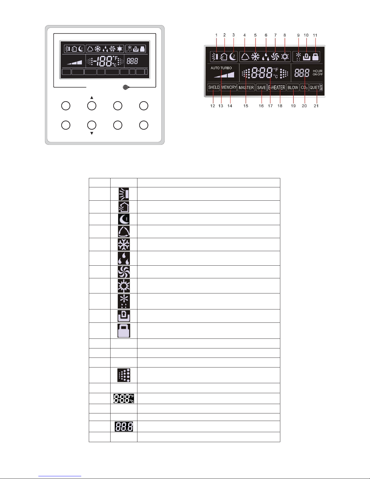
Enter/cancel
Enter/Cancel Fan Mode
Function Timer On/Off
SHIELD
MEMORY
MASTER
SAVE
BLOW
QUIET
CO
2
AUTO TURBO SET
HOUR
F
E-HEATER
A
U
T
O
Fig. 1 - Wired Controller
TABLE OF CONTENTS PAGE
SAFETY CONSIDERATIONS 1.........................
WIRED REMOTE CONTROLLER 2.....................
LCD DISPLAY ICON DESCRIPTIONS 2..................
WIRED REMOTE CONTROLLER BUTTONS 3............
OPERATION INSTRUCTIONS 4........................
INSTALLATION AND DISASSEMBLY 8.................

2
WIRED REMOTE CONTROLLER
Enter/cancel
Enter/Cancel Fan Mode
Function Timer On/Off
SHIELD
MEMORY
MASTER
SAVE
BLOW
QUIET
CO
2
AUTO TURBO SET
HOUR
F
E-HEATER
A
U
T
O
Fig. 2 - Wired Remote Controller
WIRED REMOTE CONTROLLER LCD DISPLAY
Fig. 3 - LCD Display
LCD DISPLAY ICON DESCRIPTIONS
Table 1—Icon Descriptions
No. Symbols Description
1Swing function
2Air exchange function (Not available on these units)
3Sleep function (Only Sleep 1)
4Each kind of running mode of indoor unit (auto mode)
5Cooling mode
6Dry mode
7Fan mode
8Heating mode
9Defrosting function for the outdoor unit
10 Gate-control function (Not available on these units)
11 Lock function
12 SHIELD Shield functions (Button operation, temperature setting, On/Off operation,
Mode setting are disabled by the remote monitoring system.)
13 Turbo Turbo function state
14 MEMORY Memory function (the indoor unit resumes the original setting condition
following a power failure and power recovery).
15 Blinks under the unit’s ON state without operation of any button
16 SAVE Energy-saving function (Not available on these units).
17 Ambient/setting temperature value
18 E-HEATER Electric auxiliary heating function (Not available on these units).
19 BLOW Blow function
20 Timing value
21 QUIET Quiet function (two types: quiet and auto quiet) (Not available on these units)

3
WIRED REMOTE CONTROLLER BUTTONS
Enter/cancel
Enter/Cancel Fan Mode
Function Timer On/Off
14
5678
23
Fig. 4 - Wired Remote Controller Buttons
WIRED REMOTE CONTROLLER BUTTON FUNCTIONS
Table 2—Controller Button Functions
No. Name Function
1 Enter/Cancel Function selection and cancellation
2
Running temp. setting of the indoor unit, range: 60.8
°
F~86
°
F (16
°
C~30
°
C)
Timer setting, range:0.5-24 hr.
6
3 Fan Setting of the high/middle/low/auto fan speed
4 Mode Setting of the Cooling/Heating/Fan/Dry/Auto mode of the indoor unit
5 Function Switchover among the functions of Turbo/Save/Blow etc..
7 Timer Timer setting
8 On/Off Turn on/off the indoor unit
4+2
Press together for 5s under the unit’s OFF state to ENTER/CANCEL the
memory function (if the memory is set the indoor unit, after a power failure and
the power recovery, will resume it’s original setting state. If not, the indoor unit
is default to OFF after a power recovery. MEMORY OFF is the default before
delivery).
3+6
Press at the same time under the unit’s OFF state, appears on the
wired controller for the cooling only unit, while appears on the wired
controller for the cooling and heating unit.
2+6
Upon startup of the unit without malfunction or under the unit’s OFF state,
press them at the same time for 5s to enter the lock state, in which case,
any other buttons will not respond. Repress them for 5s to quit the state.
4+6 Mode If there is a preference for
°
F rather than
°
C (default), under the OFF state, press
and hold MODE and decrease temperature set point buttons together for 5
seconds.

4
OPERATION INSTRUCTIONS
ON/OFF
Press ON/OFF to turn on the unit. Press ON/OFF again to turn it off.
NOTE: Fig.5 displays the unit’s OFF state after power on. Fig.6
displays the unit’s ON state after power on.
Fig. 5 - OFF state
Fig. 6 - ON state
MODE SETTING
Under the unit’s ON state, press MODE to switch between the
operation modes in the following sequence:
Auto−Cooling−Dry−Fan−Heating
Auto Cooling Dry Fan Heating
Fig. 7 - MODE Setting
TEMPERATURE SETTING
Press or to increase or decrease the temperature. If these
buttons are pressed continuously, the temperature either increases
or decreases by 1.8_F (1_C) every 0.5s (see Fig. 8).
In the COOLING, DRY, FAN or HEATING mode, the
temperature setting range is 60.8_F ~ 86_F (16_C~30_C). In the
AUTO mode, the setting temperature can not be adjusted.
Fig. 8 - Temperature Mode
FAN SETTING
Under the ON state, press FAN and the indoor unit’s fan speed
changes circularly (see Fig. 10).
Low Middle High
Fig. 9 - Fan Mode
Enter/Cancel Fan Mode
Function
Timer On/Off
AUTO
Fig. 10 - Fan Mode

5
TIMER SETTING
Under the ON/OFF state, press TIMER to set TIMER OFF/ON.
STIMER ON mode: Press TIMER and the LCD displays
xx.x hour, with “ON” blinking. Press or to adjust the
timing value. Next, press ENTER/CANCEL to confirm.
STIMER OFF mode: Press TIMER, if LCD does not
displayxx.x hour, it means the timer setting was cancelled
(Fig. 11 displays the TIMER OFF setting, under the ON
state). Press or to adjust the timing value. Next, press
ENTER/CANCEL to confirm.
SCANCEL TIMER: After setting the timer, if TIMER is
pressed, LCD will not display “xx. HOUR” so the timer
setting is canceled.
Fig. 11 displays the TIMER OFF setting under the unit’s ON state.
Fig. 12 Displays the TIMER ON setting under the unit’s OFF state.
Fig. 11 - Timer off Setting under the unit’s ON state
Fig. 12 - Timer off Setting under the unit’s OFF state
Timer range: 0.5−24 hours
Every press of or increases or decreases the set time by 0.5 hour, If either of the arrows are pressed continuously, the set time will
increaseor decrease by 0.5 hour ever 0.5 seconds.

6
SWING MODE
SSWINGON: Press FUNCTIONunder the unit’sON state
to activate the SWING function and blinks. Next, press
ENTER/CANCEL to confirm.
SSWING OFF: When the SWING function is on, press
FUNCTION to enter the SWING setting interface . Next,
pressENTER/CANCEL to cancel the function (see Fig.13).
Fig. 13 - Swing mode
NOTES: The SLEEP, TURBO or BLOW mode is the same as the SWING mode.
Afterthe setting is made, the user must press ENTER/CANCEL to revert to the setting status or the unit stops operating automatically
five seconds later.
SLEEP MODE
SSLEEP ON: Press FUNCTION under the unit’s ON
state until the unit enters the SLEEP mode. Press
ENTER/CANCEL to confirm.
SSLEEP OFF: When the SLEEP function is activated,
pressFUNCTION to enter the SLEEP mode. Next, press
ENTER\CANCEL to exit the function.
In the COOLING or DRY modes, the temperature increases by
1.8_F (1_C) after the unit runs under the SLEEP mode for 1 hour
and 1.8_F (1_C) after another hour. Afterwards, the unit will
continue to run at this temperature.
In the HEATING mode, the temperature decreases by 1.8_F (1_C)
after the unit runs under SLEEP 1 for one hour and 1.8_F (1_C) after
another hour. Afterwards, the unit runs at this temperature (see Fig.
14).
Fig. 14 - Sleep mode

7
TURBO SETTING
STURBO: The unit on the high fan speed generates quick
cooling or heating so the room temperature can quickly
approach the setting value.
In the COOLING or HEATING mode press FUNCTION until
the unit enters the TURBO mode then press ENTER/CANCEL to
confirm.
When the TURBO function is activated, press FUNCTION to
enter the TURBO mode and then press ENTER/CANCEL to
cancel(see Fig. 15).
Fig. 15 - Turbo mode
BLOW SETTING
SBLOW Function: After the unit turns off, the water in
the indoor unit’s evaporator automatically evaporates to
avoid mildew.
In the COOLING or DRY modes, press FUNCTION until the unit
enters the BLOW mode and then press ENTER/CANCEL to
activate the function.
When the BLOW function is activated, press FUNCTION, under
the BLOW mode interface, then press ENTER/CANCEL to
cancel the function (see Fig. 16).
Fig. 16 - Blow mode
NOTE: When BLOW is activated and the user turns off the unit by pressing ON/OFF or with the remote controller, the indoor fan will run
at low speed for 2 minutes, and “BLOW” appears on the LCD. If BLOW is deactivated, the indoor fan turns off. The BLOW
function is unavailable in the FAN or HEATING mode.

8
OTHER FUNCTIONS
1. LOCK: Upon start−up, without malfunction or under the
unit’s “OFF” state, press and at the same time for 5
seconds until the wired remote controller enters the LOCK
state and the LCD displays . Next, press and
together for 5 seconds to exit this function. Under the
LOCK function, all buttons are inactive.
2. Memory:
SMemory Switchover: Under the unit’s OFF state, press
MODE and at the same time for 5 seconds to switch the
memory states between MEMORY ON and MEMORY
OFF. When this function is activated, MEMORYappears.
If this function is not set, the unit remains under the OFF
state after a power failure and the subsequent power
recovery.
SMemory Recovery: If this function has been set for the
wired remote controller, the controller, after power failure,
resumesits original running state upon power recovery.
SMemory Contents: ON/OFF, MODE, set temperature
set fan speed and LOCK function.
INSTALLATION AND DISASSEMBLY
CONNECTION TO THE HIGH WALL INDOOR
UNIT:
Consult the installation instructions of each indoor unit for proper
installation. Connect the 4−core wire shipped with the wired
controllerto the wire with a molex connector shipped with the unit
and already connected to the PCB Board to COM−INNER1.
WIRED REMOTE CONTROLLER SIGNAL LINE
CONNECTION
SOpen the indoor unit’s electrical control box cover.
SRun the signal line of the wired remote controller through
the rubber ring.
SConnect the wired remote controller’s signal line to the
indoor unit PCB’s 4−pin socket.
STighten the signal wire with ties.
SThe communication distance between the main board and
the wired remote controller can extend up to 65.62 feet ( 20
meters)(the standard distance is 26 feet (8 meters)).
WIRED REMOTE CONTROLLER INSTALLATION
1
PVC Pipe
3 4 52
Fig. 17 - Wired Remote Controller Accessories
Table 3—Accessories
No. 1 2 3 4 5
Name Socket box
embedded in wall
Wired remote
controller wall plate Screw (M4X25) Wired remote
controller front panel Screw (ST2.9X6)

9
Figure 18 displays the wired remote controller installation steps.
NOTE: There are several issues that require the installer’s attention.
1. Prior to the installation, cut off the power supply to the wire buried in the installation hole.
2. Remove the four−core twisted pair line from the installation holes and run them through the rectangular hole behind the wired remote
controller plate.
3. Secure the wired remote controller plate to the wall, over the installation hole, and then secure the plate with the screws (M4X25).
4. Insert the four−core twisted pair line into the wired remote controller slot and then buckle the front panel and the plate of the wired
remote controller together.
5. Secure the front panel and the wired remote controller plate tightly with the screws (ST2.9X6).
1
6
8 9 10
7
3 4
5
2
Fig. 18 - Installation Steps
Please pay special attention to the following directions
during the connection to avoid air conditioning malfunction
due to electromagnetic interference.
CAUTION
!
1. Separate the wired remote controller signal and
communication lines from the power cord and connection
lines between the indoor and outdoor unit, with a
minimum interval of 7.8 in (20cm), otherwise the unit’s
communication will probably malfunction.
2. If the air conditioning unit is installed in close proximity to
an electromagnetic interference, the signal and the wired
remote controller communication lines must be shielded by
twisted pair lines.
DISASSEMBLY OF THE WIRED REMOTE
CONTROLLER
Figure 19 displays the disassembly of the wired remote controller.
1 3 42
Fig. 19 - Disassembly of the Wired Remote Controller

10
ERROR DISPLAY
If there is an error occurring during the operation of the system, the error code appears on the LCD (see Fig. 20). If multiple errors occur at the
same time, the codes display circularly.
NOTE: In event of an error, turn off the unit and have unit serviced by trained service personnel.
Enter/cancel
Enter/cancel Fan Mode
Function Timer On/Off
Fig. 20 - Error Display
Table 4—Error Description
Error Error
Code Error Error
Code
Return air temperature sensor open/
short circuited F1 Drive board communication error P6
Evaporator temperature sensor open/
short circuited F2 Compressor overheating protection H3
Indoor unit liquid valve temperature
sensor open/short circuited b5 Indoor and outdoor units unmatched LP
Indoor gas valve temperature sensor
open/ short circuited b7 Communication line misconnected or
expansion valve error dn
IPM temperature sensor open/short
circuited P7 E7
Outdoor ambient temperature sensor
open/ short circuited oFnwod-pmuP3F
Outdoor unit condenser mid-tube
temperature sensor open/short circuited 5CrorrerepmuJ4F
Discharge temperature sensor open/
short circuited 1HgnitsorfeddecroF5F
Indoor and outdoor communication error E6 Compressor startup failure Lc
DC bus under-voltage protection PL High discharge temperature protection E4
8EnoitcetorpdaolrevOHPnoitcetorpegatl
ov-revosubCD
Compressor phase current sensing
circuit error U1 Whole unit over-current protection E5
Compressor demagnetization protection HE Over phase current protection P5
7HgnizinorhcnysedrosserpmoCcHnoitcetorpCFP
IPM Temperature Protection P8 IPM Current protection H5
Over-power protection L9 Compressor phase loss/reversal
protection Ld
System charge shortage or blockage
protection F0 Frequency restricted/reduced with whole
unit current protection F8
Capacitor charging error PU Frequency restricted/reduced with IPM
current protection En
High pressure protection E1 Frequency restricted/reduced with high
discharge temperature F9
Low pressure protection E3 Frequency restricted/reduced with anti-
freezing protection FH
ELgnillatsro
sserpmoC Frequency restricted/reduced with
overload protection F6
FLgnideeps-revO Frequency restricted/reduced with IPM
temperature protection EU
Drive board temperature sensor error PF Indoor unit full water error E9
AC contactor protection P9 Anti-freezing protection E2
Temperature drift protection PE AC input voltage abnormal PP
Sensor connection protection Pd Whole unit current sensing circuit error U5
DC bus voltage drop error U3 4-way valve reversing error U7
6HgnillatsrotoM3Lnoitcetorprorre1nafroodtuO
Outdoor fan 2 error protection LA PG motor zero-crossing protection U8
Copyright 2017 CAC / BDP D7310 W. Morris St. DIndianapolis, IN 46231 Edition Date: 08/17
Manufacturer reserves the right to change, at any time, specifications and designs without notice and without obligations.
Catalog No:KSACN0201AAA-02OM
Replaces: KSACN0201AAA-01OM
Table of contents
Other CAC / BDP Thermostat manuals