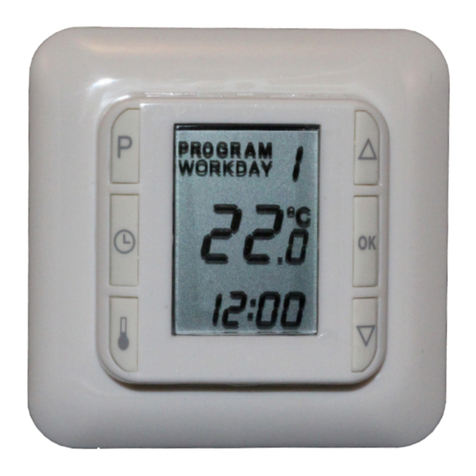
NTC HC10B Operation manual

1
INSTALLATION & USER GUIDE UK 0200008-2.3
Thermostat: HC10B
Fig. 1 Connections
L/N:LineandNeutral
Mains230-240VACconnection
OUT/N: Heatingcableconnection
Sensor:Floorsensorconnection
Earthconnectedseparately
User instructions - General information.
A) What HC10B does
HC10B is a digital thermostat for precise control of electric underfloor heating.
HC10B starts automatically in Quickstart = Manual mode and floor sensor
HC10B can also perform night and day setback in three different ways
B) IMPORTANT!
Important information before connecting the underfloor heating
To ensure optimum service life of the underfloor heating, the material in which the heating system is laid must be allowed to
dry for a minimum of 28 days before switching on the heat.
A new installation of HC10B and underfloor heating must be carried out by an authorised electrician.
Exchanging an HC10B, is allowed to do by the end-user in most countries.
HC10B must not be covered
C) Programs in HC10B
C1) Quickstart
Switch on and the underfloor heating will start up.
The temperature is set to 21OC
The temperature can be altered with [▼] and [▲]
The display shows the set temperature
The floor sensor will automatically start operation
C2) Night and day setback programs
HC10B holds three different night and day setback programmes.
They each control the temperatures and time settings. i.e. low temperature at night and during working hours, higher
temperature at morning and evening.
For each program the starting time and temperature are determined. Start times and temperatures are set at the factory, but
can be changed as required. The factory setting is shown in Table 1.
Night and day setback ensures minimum power consumption. With optimum adjustment of the underfloor heating the average
temperature can be dropped by up to 3 oC, giving potential power savings of up to 15%. The savings will naturally depend on
the circumstances and on what you want from the underfloor heating.
Max. and min. limits are in all programs Max: 27 oC Min.: 15 oC.
Program 1: Settings for Monday to Friday, and settings for Saturday and Sunday.
Program 2: Settings for All Weekdays.
Program 3: Settings for Each Day of the Week separately.
Table 1: Factory setting for night and day setback.
Times and temperatures can be changed as required. See section 3.4) and 3.5).
Technical data:
Voltage: 230-240 VAC
Frequency: 50-60 Hz
Resistiveload: 16A(3600W-230VAC)
Inductiveload: 1 A
Ingressprotection: IP30
Temperaturerange:5°C-40°C
Tolerancesensor: ±1.5 °C @ 10-30 °C
Signalsensors: Room,Floor,Combined
Sensortype: NTC 10 kΩ @ 25 °C Double
insulated
Terminals: 1.5 mm²–4.0 mm²
Apply:
LVD 2014/35/EU
EN60730-2-9
EN 50081-1
EN 50082-1
RoHS

2
Program 1: Settings for Monday to Friday, and settings for Saturday and Sunday.
Time zone
Mon - Fri
Temperature
Sat - Sun
Temperature
Wake
5:00 –8:30
22 oC
7:00 –23:00
22 oC
Leave
8:30 –15:00
18 oC
Home
15:00 –22:00
22 oC
Sleep
22:00 –5:00
18 oC
7:00 –23:00
18 oC
Program 2: Settings for All Weekdays.
Time zone
All days
Temperature
Wake
7:00 –23:00
22 oC
Sleep
23:00 –7:00
18 oC
Program 3: Settings for Each Day of the Week separately.
Time zone
Mon, Tue…..
Temperature
Wake
5:00 –8:30
22 oC
Leave
8:30 –15:00
18 oC
Home
15:00 –22:00
22 oC
Sleep
22:00 –5:00
18 oC
D) Floor and room sensors
Two sensors, a floor sensor and a room sensor provide HC10B with feedback on the current temperature in the room or the floor.
The feedback from the sensors is necessary to maintain the desired temperature in the room.
The sensors can be used separately or together.
Floor sensor (FL)
Room sensor (RO)
Combined use of room and floor sensor (CO).
In (CO) setting, the room sensor controls the room temperature, while the floor temperature*) is simultaneously monitored by
the floor sensor. The HC10B monitor is set to a desired minimum temperature and a desired maximum temperature. The
factory settings are 27 and 15oC respectively. (CO) should be selected when heating is installed under a timber floor.
*) Temperature measured by floor sensor.
E) HC10B backup battery
HC10B is equipped with a battery ensuring around 100 hours' backup. If the power has failed and the backup battery is active, the
display will show OFF. If Heat Control has been without power for more than around 100 hours, the backup battery will be empty.
When the power returns again, HC10B will start up with the factory settings Quickstart and 21 degrees.
Any changes made to the programs will be lost.
Programming the HC10B.
1) Important! Start here before you activate any night and day setback program
Set the day of the week and the clock.
Press [P] and confirm with [OK]
Hours will flash
Use [▼] or [▲] to set the hours.
Press []
Minutes will flash
Use [▼] or [▲] to set the minutes.
Press []
Day will flash
Use [▼] or [▲] to choose present day. i.e. Mon = Monday, Tue = Tuesday
Confirm by pressing [OK].
2) Setting the functions and altering the programs
2.1) Set HC10B to floor sensor
Press [] for approx. 4 secs.
(FL), (RO) or (CO) will flash on the display.
Press one of the arrow keys [▼] or [▲] until (FL) shows on the display.
Confirm by pressing [OK].
The underfloor heating will now be controlled by the signal from the floor sensor. The display will show the temperature the floor will
reach.
Note: The temperature shown on the display will typically be lower than the room temperature.
2.2) Setting HC10B to room sensor
The use of room sensor is recommended if there is no floor sensor in the floor.
Press [] for approx. 4 secs.
(FL), (RO) or (CO) will flash on the display.
Press one of the arrow keys [▼] or [▲] until (RO) shows on the display.
Confirm by pressing [OK].
The underfloor heating will now be controlled by the signal from the room sensor. The display will show the temperature the air in
the room will reach. Room sensor can be calibrated if desired (see point 13).

3
2.3) Setting HC10B to combined room and floor sensor
Note: This setting is used when using the heating under a timber floor
Press [] for approx. 4 secs.
(FL), (RO) or (CO) will flash on the display.
Press one of the arrow keys [▼] or [▲] until (CO) shows on the display.
Confirm by pressing [OK].
The thermostat is now set to combined floor and room sensor.
The choice of combined room and floor sensor activates monitoring of the temperature in the floor. Temperature monitoring is set at
the factory to max. +27 oC and min. +15 oC.
By using the floor sensor, HC10B will now ensure that the floor temperature#) is never higher than + 27 oC nor lower than + 15 oC.
These values can be adjusted as desired.
#) Temperature measured by floor sensor.
Limiting the maximum temperature in the floor is important when the heating is installed under a timber floor. Leading suppliers of
timber floors prescribe a maximum temperature of 27oC on the surface of their floors.
Find out what the supplier of your timber floor recommends. Set the maximum value to the prescribed temperature.
3) Night and day setback settings
3.1) Setting HC10B to operate night and day setback.
Press [P]
PROGRAM will flash
Press [OK]
HC10B will now operate night and day setback
3.2) Changing between night and day setback programs 1, 2 or 3
Press [P]
Program on the display will flash
Use [▼] or [▲] to set the desired Program
Exit by pressing [OK]
3.3) Read the current settings
Press [P]
Press [P]
Current weekday(s) will flash.
Use [▼] or [▲] to choose day(s)
Press [P]
The time zone setting on the display will flash
Use [▼] or [▲] to view the time zone time and temperature incl. Max. and Min. settings.
Exit by pressing [OK] and [OK]
3.4) Changing time settings for night and day setback
Press [P] followed by [▼] or [▲] to the program you wish to change; the display will flash.
Press []
The hours on the time display will flash
Use [▼] or [▲] to set the hour figure.
Press []
The minutes on the time display will flash
Use [▼] or [▲] to set the minute figure.
Press [OK]
The selected Time zone will flash.
Use [▼] or [▲] to select the program you wish to change next.
or
Exit by pressing [OK] and [OK].
3.5) Changing temperature settings for night and day setback
Press [P]
PROGRAM will flash
Press [▼] or [▲] to the program you wish to change; the display will flash.
Press []
The temperature will flash
Use [▼] or [▲] to set the temperature.
Press [OK]
The selected Time zone will flash.
Use [▼] or [▲] to select the program you wish to change next.
or
Exit by pressing [OK]
4) Override
4.1) Temporarily override the temperature with “Econ” or “Comf”
If the time zone is in “Leave” or “Sleep” the override will go into “Econ” and lover the temperature until the next time zone gets
active.
If the time zone is in “Wake” or “Home” the override will go into “Comf” and raise the temperature until the next time zone gets
active.

4
Press [▼] or [▲]. until you get to the program you wish to activate; the display will flash.
Comf or Econ will show in the display. Also the temperature will flash
Press [OK]
4.2) Deactivate “Econ” or “Comf”
If the time zone temperature is overridden by “Econ” or “Comf”, it can be deactivated like this:
Press [P]
Press [▲]
Program will flash
Press [OK] “Econ” or “Comf” is now no longer active and is not displayed
5) Changing max. and min. limits for monitoring floor temperature –in day and night setback
This function is only active, if HC10B has been selected to operate with combined room and floor sensor (CO)
Changing the factory-set values of max. 27 oC and min. 15 oC
Press [P]
PROGRAM will flash
Press [P]
The day(s) on the display will flash
Press [P]
Time zone will flash
Press [▼] or [▲] until program Max or Min flashes on the display.
Press []
The temperature will flash
Use [▼] or [▲] to set the temperature.
Press [OK]
The selected PROGRAM will flash.
Use [▼] or [▲] to select the program which you now wish to change.
or
Exit by pressing [OK] for 2 seconds.
5a) Changing max. limit - in Quickstart
The function is active when the floor sensor is connected / installed. Limit temperature is measured by the floor sensor.
Select maximum limitation temperature. The factory setting is 27 oC. Possible setting is 26 to 45 oC.
Press [] for 2 seconds.
Sensor will flash.
Press []
The temperature will flash.
Use [▼] or [▲] to change the limit temperature.
Exit by pressing [OK]
6) Changing from Quickstart to Night and day setback
Change from Quickstart program to Night and day setback program
Press [P]
PROGRAM will flash
Press [OK]
HC10B will now operate night and day setback
The previously set times and temperatures in Night and day setback are saved.
7) Changing from Night and day setback to Quickstart
Change from Night and day setback program to Quickstart program
Press []
FL: - - flashes
Press [OK]
HC10B will now operate with Quickstart.
The previously set times and temperatures in Night and day setback are not deleted on changing to Quickstart.
8) Switching between display of actual room temperature and desired temperature
Simultaneously press []+[OK]. Hold them in for min. 3 seconds.
This will switch the display between actual or desired room temperature.
Switch back in the same way.
Simultaneously press []+[OK]. Hold them in for min. 3 seconds.
The display will switch back again.
9) Read out actual floor temperature
Apply only if floor sensor is connected
Press []
Actual temperature is shown in the display for 10 seconds. I.e. FL :22
10) Turning HC10B on and off
Press [▼] and [▲] simultaneously.
HC10B will turn off
Press any key to turn HC10B on again

5
11) Resetting HC10B
This procedure will return HC10B to Quickstart. Any changed values in night and day setback will be lost.
Press and hold first [] then [▼] then [ P ] and finally [▲] –hold all 4 buttons for 4 seconds.
The display will go out and then everything will turn on again.
HC10B has now been reset and will be in Quickstart / manual mode.
12) Floor sensor status
Press []
FL: - -, sensor not connected, disconnected or short-circuited
FL: HI, other errors
13) Calibrating Room sensor.
This procedure will enable Room sensor to be calibrated by +/- 0 to 5 degrees C.
Suggestion: Before calibration, first set the thermostat to room sensor (see point 2.2). Then set the display to read out the
actual room temperature (see point 8)
After the calibration has been made the temperature can be switched back to desired temperature displayed (see point 8).
After calibration –wait half an hour and then check the temperature. After half an hour, the temperature is stable and the
temperature generated by the display light will no longer influence the room sensor.
Please note that the room temperature is influenced by many factors and will be less accurate than the floor sensor (see point
F.2).
Press [P] and hold. Then press also [] and hold both down for 16 sec.
Offset temperature will flash.
Use [▼] or [▲] to set the room temperature sensor offset +/- 0 to 5 degrees C.
Confirm by pressing [OK]. After approx. 45 s. the calibration will be active.
Installation
F) Positioning, installation and connection
F.1) Position and connection of floor sensor
Position of floor sensor in the room.
Position the floor sensor about 0.5 m from the wall.
Position the floor sensor near the HC10B. This gives the simplest installation.
If desired, the floor sensor cable can be extended.
Optional extension of floor sensor cable
Use ordinary doorbell cable to extend the floor sensor cable. Maximum extension 9m.
Position of floor sensor in floor.
Position the floor sensor in a pipe approximately half-way between two heating cables.
If necessary, the sensor may be placed in a grouting gap, without the use of I pipe.
Note: When positioning in a grouting gap, any regrouting should be undertaken with care in order not to damage the sensor.
Connection of floor sensor.
Connect the floor sensor to the HC10B as shown on the diagram.
F.2) Position and mounting of HC10B
Important! HC10B must not be covered.
If the floor sensor (FL) is used, any position may be used.
If the room sensor (RO) or combined room and floor sensor (CO) are used, HC10B must be positioned approximately 1.2
m above the floor.
Avoid:
Heat from radiators, wood-burning stoves and other heaters
Cold outer walls
Concealed pipes or chimneys which give off heat
Direct sunlight or positioning behind curtains
Installation can be carried out in two different ways:
Flush-mounted in the wall
Surface-mounted on the wall
Selection of installation box for flush mounting
For walls of wood, plasterboard etc, use flush-mounting box (53000003)
For walls of brick, concrete etc., use flush-mounting box (53000002)
Selection of installation box for surface mounting
When mounting on the surface of a wall, use surface-mounting box (53000001).

6
Installation and connection of HC10B
Remove the front cover from the display by inserting a small screwdriver in the square hole on top of the thermostat. At the same
time, carefully lift the front cover outwards. Then remove the frame.
Connect wires and sensors to HC10B in accordance with the diagram.
Connection must be made by an authorised electrician.
Important! See section, “Starting up underfloor heating with HC10B”, before turning on the power.
Replace the frame and press on the cover. Activate the lock with a click.
Other manuals for HC10B
1
Table of contents
Other NTC Thermostat manuals
Popular Thermostat manuals by other brands

Ecobee
Ecobee Smart Si installation manual

Hunter
Hunter 40120 Installation and operation manual

suntouch
suntouch SunStat Command 108001 Installation and operation manual

Watts Industries
Watts Industries WFHT BASIC 24V quick start guide

OJ Electronics
OJ Electronics OCC2-1991H1 user manual

Lennox
Lennox S40 quick start guide