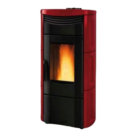
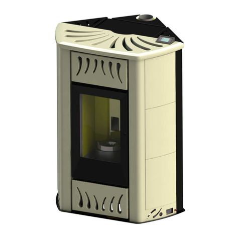
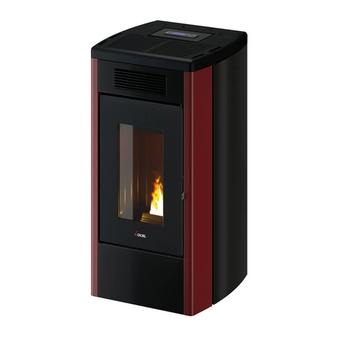
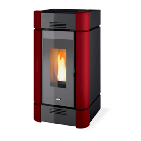
Cadel IDRO PRINCE3 12 User manual

USER MANUAL
PELLETTHERMOSTOVE
EN
©2020 CADEL srl | All rights reserved - Tutti i diritti riservati
IDRO PRINCE312-16-23-23H2O-30-30H2O -
IDRO RIVER316-23-23H2O - AQUOS316-23-23H2O -
IDRON 16-22 AIRTIGHT - MIRA 16-22 - TESIS 16-23 AIRTIGHT
- HIDROFIRE 22.8 - MAYA316-24

CADEL SRL - Via Foresto Sud, 7 - 31025 Santa Lucia di Piave (TV) - ITALY - Tel. +39 0438 738669 - Fax +39 0438 73343 - customercare@cadelsrl.com - www.cadelsrl.com
Iscr. registro imprese / Partiva Iva IT 03202180265 - R.E.A.TV 227665 - Capitale Sociale i.v. € 30.000,00
TECHNICAL DOCUMENTATION FOR LOCAL SPACE HEATERS ACCORDING TO COMMISSION
REGULATIONS (EU) 2015/1185 - (EU) 2015/1186 (PRODUCT FICHE)
Manufacturer CADEL srl - Via Foresto Sud 7 - 31025 Santa Lucia di Piave (TV) - Italy
Trademak: model identier
CADEL: AQUOS3 16 -IDRO RIVER3 16- MAYA3 16- IDRO PRINCE3 16
FREEPOINT:TESIS 16 AT
PEGASO: MIRA 16
Description Pellet stove
Indirect heating functionality Yes
Direct heat output 3,3 kW
Indirect heat output 12,9 kW
CPR harmonised standard EN 14785
Notied body KIWA CERMET ITALIA S.P.A.(N.B.0476)
Preferred fuel (unique) Compressed wood with moisture content < 12 % YES
Wood logs with moisture content ≤ 25 % NO
Other woody biomass NO
ηs82 %
EEI 124 -
Energy Eciency Class (A++ to G scale) A+
Space heating emissions at nominal heat output
PM (al 13% O2)19 mg/Nm3
OGC (al 13% O2)2,2 mg/Nm3
CO (al 13% O2)74 mg/Nm3
NOx(al 13% O2)109 mg/Nm3
Space heating emissions at minimum heat output
Only required if correction factors F(2) or F(3) are applied
PM (al 13% O2)28 mg/Nm3
OGC (al 13% O2)7,7 mg/Nm3
CO (al 13% O2)138 mg/Nm3
NOx(al 13% O2)133 mg/Nm3
Heat output Nominal heat output (Pnom)16,2 kW
Minimum heat output (indicative) (Pmin)4,7 kW
Useful eciency (NCV as received) Useful eciency at nominal heat output (ηth,nom)93,3 %
Useful eciency at minimum heat output (indicative) (ηth,min)96,5 %
Auxiliary electricity consumption At nominal heat output (elmax)0,115 kW
At minimum heat output (elmin)0,060 kW
In standby mode (elsb)0,004 kW
Type of heat output/room temperature control (select one)
Single stage heat output, no room temperature control NO
Two or more manual stages, no room temperature control NO
With mechanic thermostat room temperature control NO
With electronic room temperature control NO
With electronic room temperature control plus day timer NO
With electronic room temperature control plus week timer YES
Other control options (multiple selections possible) Room temperature control, with presence detection NO
Room temperature control, with open window detection NO
With distance control option NO
Permanent pilot ame power requirement Pilot ame power requirement (if applicable) (Ppilot)N.A. kW
Observe the specic precautions for installation, assembly and maintenance indicated in the manual accompanying the product.
Issue date: 18.11.2021

CADEL SRL - Via Foresto Sud, 7 - 31025 Santa Lucia di Piave (TV) - ITALY - Tel. +39 0438 738669 - Fax +39 0438 73343 - customercare@cadelsrl.com - www.cadelsrl.com
Iscr. registro imprese / Partiva Iva IT 03202180265 - R.E.A.TV 227665 - Capitale Sociale i.v. € 30.000,00
TECHNICAL DOCUMENTATION FOR LOCAL SPACE HEATERS ACCORDING TO COMMISSION
REGULATIONS (EU) 2015/1185 - (EU) 2015/1186 (PRODUCT FICHE)
Manufacturer CADEL srl - Via Foresto Sud 7 - 31025 Santa Lucia di Piave (TV) - Italy
Trademak: model identier
CADEL: AQUOS3 23 -IDRO RIVER3 23- MAYA24- IDRO PRINCE3 23
FREEPOINT:TESIS 23 AIRTIGHT
PEGASO: MIRA 22
Description Pellet stove
Indirect heating functionality YES
Direct heat output 4,1 kW
Indirect heat output 18,7 kW
CPR harmonised standard EN 14785
Notied body KIWA CERMET ITALIA S.P.A.(N.B.0476)
Preferred fuel (unique) Compressed wood with moisture content < 12 % YES
Wood logs with moisture content ≤ 25 % NO
Other woody biomass NO
ηs80 %
EEI 122 -
Energy Eciency Class (A++ to G scale) A+
Space heating emissions at nominal heat output
PM (al 13% O2)19 mg/Nm3
OGC (al 13% O2)3mg/Nm3
CO (al 13% O2)169 mg/Nm3
NOx(al 13% O2)114 mg/Nm3
Space heating emissions at minimum heat output
Only required if correction factors F(2) or F(3) are applied
PM (al 13% O2)28 mg/Nm3
OGC (al 13% O2)7,7 mg/Nm3
CO (al 13% O2)138 mg/Nm3
NOx(al 13% O2)133 mg/Nm3
Heat output Nominal heat output (Pnom)22,8 kW
Minimum heat output (indicative) (Pmin)4,7 kW
Useful eciency (NCV as received) Useful eciency at nominal heat output (ηth,nom)91,3 %
Useful eciency at minimum heat output (indicative) (ηth,min)96,5 %
Auxiliary electricity consumption At nominal heat output (elmax)0,115 kW
At minimum heat output (elmin)0,060 kW
In standby mode (elsb)0,004 kW
Type of heat output/room temperature control (select one)
Single stage heat output, no room temperature control NO
Two or more manual stages, no room temperature control NO
With mechanic thermostat room temperature control NO
With electronic room temperature control NO
With electronic room temperature control plus day timer NO
With electronic room temperature control plus week timer YES
Other control options (multiple selections possible) Room temperature control, with presence detection NO
Room temperature control, with open window detection NO
With distance control option NO
Permanent pilot ame power requirement Pilot ame power requirement (if applicable) (Ppilot)N.A. kW
Observe the specic precautions for installation, assembly and maintenance indicated in the manual accompanying the product.
Issue date: 18.11.2021

CADEL SRL - Via Foresto Sud, 7 - 31025 Santa Lucia di Piave (TV) - ITALY - Tel. +39 0438 738669 - Fax +39 0438 73343 - customercare@cadelsrl.com - www.cadelsrl.com
Iscr. registro imprese / Partiva Iva IT 03202180265 - R.E.A.TV 227665 - Capitale Sociale i.v. € 30.000,00
TECHNICAL DOCUMENTATION FOR LOCAL SPACE HEATERS ACCORDING TO COMMISSION
REGULATIONS (EU) 2015/1185 - (EU) 2015/1186 (PRODUCT FICHE)
Manufacturer CADEL srl - Via Foresto Sud 7 - 31025 Santa Lucia di Piave (TV) - Italy
Trademak: model identier
CADEL: IDRO PRINCE3 12
FREEPOINT:
PEGASO:
Description Pellet stove
Indirect heating functionality Yes
Direct heat output 1,6 kW
Indirect heat output 10,2 kW
CPR harmonised standard EN 14785
Notied body KIWA CERMET ITALIA S.P.A.(N.B.0476)
Preferred fuel (unique) Compressed wood with moisture content < 12 % YES
Wood logs with moisture content ≤ 25 % NO
Other woody biomass NO
ηs80 %
EEI 122 -
Energy Eciency Class (A++ to G scale) A+
Space heating emissions at nominal heat output
PM (al 13% O2)18 mg/Nm3
OGC (al 13% O2)2mg/Nm3
CO (al 13% O2)35 mg/Nm3
NOx(al 13% O2)109 mg/Nm3
Space heating emissions at minimum heat output
Only required if correction factors F(2) or F(3) are applied
PM (al 13% O2)23 mg/Nm3
OGC (al 13% O2)12 mg/Nm3
CO (al 13% O2)475 mg/Nm3
NOx(al 13% O2)75 mg/Nm3
Heat output Nominal heat output (Pnom)11,8 kW
Minimum heat output (indicative) (Pmin)3,2 kW
Useful eciency (NCV as received) Useful eciency at nominal heat output (ηth,nom)91,8 %
Useful eciency at minimum heat output (indicative) (ηth,min)92,4 %
Auxiliary electricity consumption At nominal heat output (elmax)0,075 kW
At minimum heat output (elmin)0,060 kW
In standby mode (elsb)0,004 kW
Type of heat output/room temperature control (select one)
Single stage heat output, no room temperature control NO
Two or more manual stages, no room temperature control NO
With mechanic thermostat room temperature control NO
With electronic room temperature control NO
With electronic room temperature control plus day timer NO
With electronic room temperature control plus week timer YES
Other control options (multiple selections possible) Room temperature control, with presence detection NO
Room temperature control, with open window detection NO
With distance control option NO
Permanent pilot ame power requirement Pilot ame power requirement (if applicable) (Ppilot)N.A. kW
Observe the specic precautions for installation, assembly and maintenance indicated in the manual accompanying the product.
Issue date: 18.11.2021

89CD220020EN
TECHNICAL DOCUMENTATION FOR LOCAL SPACE HEATERS ACCORDING TO COMMISSION
REGULATIONS (EU) 2015/1185 - (EU) 2015/1186 (PRODUCT FICHE)
Manufacturer CADEL srl - Via Foresto Sud 7 - 31025 Santa Lucia di Piave (TV) - Italy
Trademak: model identier CADEL: IDRO PRINCE 30
Description Pellet stove
Indirect heating functionality YES
Direct heat output 1,7 kW
Indirect heat output 26,9 kW
CPR harmonised standard EN 14785
Notied body KIWA CERMET ITALIA S.P.A.(N.B.0476)
Preferred fuel (unique) Compressed wood with moisture content < 12 % YES
Wood logs with moisture content ≤ 25 % NO
Other woody biomass NO
ηs83 %
EEI 125 -
Energy Eciency Class (A++ to G scale) A+
Space heating emissions at nominal heat output
PM (al 13% O2)18 mg/Nm3
OGC (al 13% O2)2mg/Nm3
CO (al 13% O2)104 mg/Nm3
NOx(al 13% O2)127 mg/Nm3
Space heating emissions at minimum heat output
Only required if correction factors F(2) or F(3) are applied
PM (al 13% O2)21 mg/Nm3
OGC (al 13% O2)6mg/Nm3
CO (al 13% O2)223 mg/Nm3
NOx(al 13% O2)98,6 mg/Nm3
Heat output Nominal heat output (Pnom)28,6 kW
Minimum heat output (indicative) (Pmin)7,7 kW
Useful eciency (NCV as received) Useful eciency at nominal heat output (ηth,nom)93,6 %
Useful eciency at minimum heat output (indicative) (ηth,min)94,7 %
Auxiliary electricity consumption At nominal heat output (elmax)0,115 kW
At minimum heat output (elmin)0,060 kW
In standby mode (elsb)0,004 kW
Type of heat output/room temperature control (select one)
Single stage heat output, no room temperature control NO
Two or more manual stages, no room temperature control NO
With mechanic thermostat room temperature control NO
With electronic room temperature control NO
With electronic room temperature control plus day timer NO
With electronic room temperature control plus week timer YES
Other control options (multiple selections possible) Room temperature control, with presence detection NO
Room temperature control, with open window detection NO
With distance control option NO
Permanent pilot ame power requirement Pilot ame power requirement (if applicable) (Ppilot)N.A. kW
Observe the specic precautions for installation, assembly and maintenance indicated in the manual accompanying the product.
Issue date: 18.11.2021

DISPOSAL OF MATERIALS
WARNINGS FORTHE CORRECT DISPOSAL OF THE PRODUCT
The owner is the sole party responsible for demolishing and disposing of the product.This must be performed in compliance with
laws related to safety and environmental protection in force in his/her country.
At the end of its working life, the product must not be disposed of as urban waste.
It must be taken to a special differentiated waste collection centre set up by the local authorities or to a retailer that provides this
service.
Separating and recycling prevents potential negative effects on the environment and health (often caused by inappropriately
disposing of product parts). It also allows materials to be recovered in order to obtain significant savings in energy and resources.
The following table and the exploded view it refers to highlight the main components that can be found in the device and indica-
tions on how to separate and dispose of them correctly when no longer used.
More specifically, the electric and electronic components must be separated and disposed of in authorised centres, in compliance
with theWEEE directive 2012/19/EU and the relative national transpositions.
Exploded drawing
LEGENDA WHERE TO DISPOSE MATERIALS
A. OUTER CLADDING If there is any, to be disposed of separately based on
the material used:
Metal
Glass
Tiles or ceramics
Stone
B. GLASS DOORS If there is any, to be disposed of separately based on
the material used:
Glass ceramic (fire door): to be disposed of with inert
or mixed waste
Tempered glass (oven door): to be disposed of with
glass
C. INTERIOR CLADDING If there is any, to be disposed of separately based on
the material used:
Metal
Refractory materials
Insulating panels
Vermiculite
Insulation, vermiculite and refractory materials that
have come into contact with flames or exhaust gases
(dispose of in mixed waste)

LEGENDA WHERE TO DISPOSE MATERIALS
D. ELECTRIC AND ELECTRO-
NIC COMPONENTS
To be disposed of separately in authorised centres, as
indicated in theWEEE directive 2012/19/EU and the
relative national transposition.
Wiring, motors, fans, circulators, display panels, sen-
sors ignition plug, electronic cards, batteries.
E. METAL STRUCTURE To be disposed of separately with metal -
F. COMPONENTS THAT CAN-
NOT BE RECYCLED To be disposed of with mixed waste E.G.: Gaskets, rube piping, silicone or fibres, plastic.
G. HYDRAULIC COMPONENTS Piping, fittings, expansion vessel, valves. If there are
any, to be disposed of separately based on themate-
rial they are made of:
Copper
Brass
Stainless steel
Other materials
INSTRUCTIONS FOR PACKAGING DISPOSAL
The material that the appliance’s packaging is made of must be managed correctly, in order to make collection, reuse, recovery
and recycling easier, where possible.
The table below illustrates the possible components that the packaging is made of, and the relative instructions for correct dispo-
sal.
DESCRIPTION CODE MATERIAL SYMBOL DIRECTIONS FOR COLLECTION
-WOOD BED
-WOOD CAGE
-WOOD PALLET
WOOD
FOR 50
SORTED waste collection
WOOD
Check with the competent body on
how to dispose of this packaging at
the recycling depot
- CARDBOARD BOX
- CARDBOARD CORNER
- CARDBOARD SHEET
CORRUGATED CARDBOARD
PAP 20
SORTED waste collection
PAPER
Check the instructions of the compe-
tent body
- APPLIANCE BAG
- BAG OF ACCESSORIES
- BUBBLEWRAP
- PROTECTIVE SHEET
- LABELS
POLYETHYLENE
LD PE 04
SORTED waste collection
PLASTIC
Check the instructions of the compe-
tent body
- POLYSTYRENE
- FOAM PEANUTS POLYSTYRENE
PS 6
SORTED waste collection
PLASTIC
Check the instructions of the compe-
tent body
- STRAP
-TAPE POLYPROPYLENE
PP 5
SORTED waste collection
PLASTIC
Check the instructions of the compe-
tent body.
- SCREWS
- STAPLES FOR STRAP
- FASTENING BRACKET
IRON
FE 40
SORTED waste collection
METAL
Check with the competent body on
how to dispose of this packaging at
the recycling depot

IDROSTUFE
2
SUMMARY
1 MANUAL SIMBOLOGY....................................3
2 DEAR CUSTOMER..........................................3
3 CAUTIONS....................................................3
4 SAFETY REQUIREMENTS ...........................4
5 WARRANTY CONDITIONS...............................5
5.0.1 PRODUCT PERFORMANCE CHECKS .......................6
6 SPARE PARTS ...............................................6
7 WARNINGS FOR THE CORRECT DISPOSAL OF THE
PRODUCT ...........................................................6
7.1 INFORMATION FOR MANAGEMENT OF ELECTRIC AND
ELECTRONIC APPLIANCEWASTE CONTAINING BATTERIES OR
ACCUMULATORS................................................................7
8 WIFI CONNECTION BLUETOOTH.................7
8.1 EASY CONNECT PLUS...............................................7
8.2 NAVEL STAND ALONE..............................................8
9 USE .............................................................9
9.1 INTRODUCTION.......................................................9
9.2 CONTROL PANEL DISPLAY.......................................9
9.3 MAIN MENU............................................................9
9.4 SETTINGS MENU....................................................10
9.5 AUTO ECO MODE SEE SECTION FG.....................14
9.6 PROGRAMMED MODE TIMER MAIN MENU......14
9.7 NOTES FOR TIMER OPERATION..............................15
9.8 SLEEP FUNCTION MAIN MENU...........................15
10 FIRST IGNITION WARNINGS ........................16
10.1 START UP ..............................................................16
10.2 GENERAL WARNINGS............................................16
10.3 POWER OUTPUT....................................................17
10.4 ADJUSTMENTS MENU ...........................................17
10.5 NORMAL SHUTDOWN ON THE PANEL: OFF WITH
FLASHING FLAME...........................................................17
10.6 POWER FAILURE....................................................18
10.7 FAILED IGNITION...................................................18
11 RECOMMENDATIONS FOR SAFE USE .............18
12 FUEL..........................................................19
12.1 FUEL......................................................................19
12.2 PELLET SUPPLY .....................................................19
13 LOADING PELLETS ......................................19
13.1 LOADING PELLETS.................................................19
13.2 USERTRAINING.....................................................20
14 SAFETY DEVICES AND ALARMS ....................20
14.1 SAFETY DEVICES ...................................................20
14.2 PRESSURE SWITCH................................................20
14.3 SMOKETEMPERATURE PROBE ..............................21
14.4 CONTACT THERMOSTAT INTHE FUEL HOPPER.......21
14.5 ELECTRICAL SAFETY..............................................21
14.6 SMOKE FAN ...........................................................21
14.7 GEAR MOTOR.........................................................21
14.8 TEMPORARY POWER CUT......................................21
14.9 FAILED STARTUP..................................................21
14.10 BLACKOUTWITH THE BOILER ON..........................21
14.11 BLACKOUT OF MORE THAN 10'' DURING STOVE
SHUTDOWN.....................................................................21
14.12 CONTACTTHERMOSTAT IN THE BOILER.................21
14.13 WATERTEMPERATURE PROBE...............................21
14.14 ANTIFREEZE FUNCTION.........................................21
14.15 PUMP ANTISEIZURE FUNCTION...........................21
14.16 ALARM ALERTS .....................................................22
14.17 ALARM RESET .......................................................23
15 ROUTINE MAINTENANCE.............................23
15.1 INTRODUCTION.....................................................23
15.2 BEFORE EACH STARTUP.......................................23
15.3 HOPPER CLEANING ...............................................24
15.4 ASH DRAWER CLEANING IDROPRINCE AQUOS
IDRON MIRA TESIS ......................................................24
15.5 ASH DRAWER CLEANING MAYA.............................24
15.6 CLEANINGTHE GLASS ...........................................25
15.7 CLEANINGTHE EXCHANGER ANDTHE COMPARTMENT
UNDERTHE BRAZIER EVERY 2/3 DAYS.............................25
15.8 PIPE UNIT CLEANING.............................................26
15.9 FUME PIPES ANNUAL CLEANING .........................26
15.10 GENERAL CLEANING..............................................26
15.11 CLEANING OF PAINTED METAL PANELS ................26
15.12 CLEANING OF CERAMIC AND STONE PANELS........26
15.13 SWITCHING OFF ATTHE END OF THE SEASON.......27
15.14 CHECKINGTHE INNER COMPONENTS....................27
16 IN CASE OF ANOMALY..................................28
16.1 PROBLEM SOLVING...............................................28
16.2 PROBLEM SOLVING THERMOSTOVE...................32
3
IDROSTUFE
1 MANUAL SIMBOLOGY
USER
AUTHORISED TECHNICIAN
(ONLY to interpret or the Stove-manufacturer or the Authorized Techni-
cian of Technical Assistance Service approved by the Stove-manufacturer)
SPECIALIZED STOVE-REPAIRER
CAUTION:
READ CAREFULLY THE NOTE
CAUTION:
DANGER OR IRREVERSIBLE DAMAGE POSSIBILITY
• The icons with the stylized figures indicates whom the subject dealt in the paragraph is addressed to (between the User and/
or the AuthorizedTechnician and/or the Specialized Stove-repairer).
• WARNING symbols indicates an important note.
2 DEAR CUSTOMER
• Dear Customer,
• Our products are designed and manufactured in compliance with European regulations harmonised with Regulation (EU) no.
305/2011 for construction products (EN13240 for wood-burning stoves, EN14785 for pellet-burning appliances, EN13229 for
fireplaces/wood-burninginserts and EN 12815for wood-burningrange cookers),withhigh qualitymaterialsand extensiveex-
perience in transformation processes.The products also comply with the essential requirements of Directive 2009/125/EC (Eco
Design) and, where applicable, Directives 2014/35/EU (Low Voltage), 2014/30/EU (Electromagnetic Compatibility), 2014/53/
EU (Radio Frequency), 2011/65/EU (ROhS).
• Read carefully the instruction contained in this manual to obtain the best efficiency.
• This instruction manual is an integral part of the product: make sure it is delivered with the appliance also in case of sold to
others. In case of loss please ask a copy to your localTechnical Assistance Service.
In Italy biomass system installation below 35 kW must comply with MD 37/08. Every qualified installer who
own these requirements, has to issue the certificate of conformity for the installed system ("system" means:
stove + chimney + air inlet).
• According to (EU) No. 305/2011 regulation, the“ Declaration of Performance”and“Declaration of Conformity”are avai-
lable online at the web sites:
- www.cadelsrl.com
- www.free-point.it
- www.pegasoheating.com
3 CAUTIONS
• All the pictures carried in this manual are only for indicative and explanatory purpose and could therefore slightly differ from
your appliance.
• The referring appliance is those you purchased.
• In case of doubts or difficulties in the comprehension or for problems not described in this manual, please promptly contact
your distributor or installer.

IDROSTUFE
4
4 SAFETY REQUIREMENTS
• Installation, electrical connection, functional verification and maintenance must only be
performed by qualified or authorised personnel.
• Live electrical parts: disconnect the product from the 230V power supply before perfor-
ming any maintenance operation. Only power the product after completing assembly.
• Special maintenance must only be performed by authorised and qualified personnel.
• All local regulations, including those referring to national European standards, must be
respected during appliance installation.
• The manufacturer declines any responsibility in case of installation which are not in complian-
ce with current regulations, in case of a wrong room ventilation system, in case of an electric con-
nection which is not in compliance with regulations and in case of a wrong use of the appliance.
• It is forbidden to install the stove in bedrooms, bathrooms and in rooms used for storing
combustible materials and in one-room flats.
• The installation in one-room flats is allowed if they are in sealed chamber.
• In any case the stove must not be installed in rooms where it can get in touch with water or
water splashes because this can cause burn hazards and short-circuit.
• Please check that the floor has an adequate load capacity. If the existing one does not
satisfy this requirement, appropriate measure should be provided (for example a plate for di-
stributing the load).
• For safety fire regulations the distances from flammable or sensible to heat objects (sofas,
pieces of furniture, wooden covering, etc...) must be respected.
• If there are highly flammable objects (curtains, fitted carpet, etc...), all these distances
must be further increased with 1 meter.
• If the floor is made of combustible material, we recommend using a protector made of in-
combustible material (steel, glass, etc.) that also protects the front part from any falling burnt
particles during cleaning.
• The electrical cable must not get in touch with the fume exhaust pipe and nor with every
other part of the stove.
• The user, or whoever is operating the product, must read and fully understand the contents
of this installation and use guide before performing any operation. Errors or incorrect settings
can cause hazardous conditions and/or poor operation.
• The type of fuel to use is only the pellets.
• Do not use the appliance as waste inceneretor.
• Do not place laundry on the product to dry. Any clothes horses or similar objects must be
kept at a safe distance from the product. Fire hazard.
• It is forbidden to operate the product with the door open or the glass broken.
• It is forbidden to modify the appliance without authorization.
• Do not use flammable liquids during the ignition (alcool, petrol, oil, etc...).
• After a failed ignition the burning pot must be empty from the amassed pellets, before
starting the stove up again.
• The pellet hopper must always be closed with its own lid.
• Before of every intervention leave the fire completely extinguish till the cooling and always
disconnect the plug from the electric socket.
• This appliance can be used by children aged from 8 years and above and persons with re-
duced physical, sensory or mental capabilities or lack of experience and knowledge if they
have been given supervision or instruction concerning use of the appliance in a safe way and
understand the hazards involved. Children shall not play with the appliance. Cleaning and
user maintenance shall not be made by children without supervision.
• Packaging are not toys and could cause suffocation or strangulation and other health ha-
zards! People (childreen included) with reduced mobility, psycological deseases or without
experience and knowledge must be kept away from packaging. The stove is not a toy.

5
IDROSTUFE
• Childreen must be constantly overseen in order to assure that they do not play with the appliance.
• During its running, the stove reaches high temperatures: keep away childreen and animals
and for your safety please use appropriate fireproof devices, such as heat-protecting gloves.
• The chimney flue must be cleaned, since the soot and unburnt oil deposits reduce its sec-
tion so blocking the draught. In great quantities they can flare up.
• If the pellets are of bad quality (if contains sizing agents, oils, varnishes, plastic remains or
if it is mealy), deposits will form along pellets drop pipe during the running.When the stove is
switched off, these remains could form little hot coals that rising along the pipe could reach the
pellets on the hopper burning them and creating a thick and harmful smoke inside the room.
Please always keep the hopper closed with its own lid. If the pipe is sooty, please clean it.
• In case it would be necessary to extinguish the fire emitted by the stove or by the chimney
flue, use a fire-extinguisher or contact the firemen. Do not use water to extinguish the fire
inside the burning pot.
• Shut the stove down in the event of a breakdown or bad running and contact the speciali-
sed technician immediately.
• Pellets must not be fed manually into the burner - this wrong behaviour can generate an
abnormal amount of unburned gas, with a risk of explosion in the chamber.
• Accumulatedunburntpelletsintheburner afterafailedignitionsmustbe removedbeforelighting.
• PROCEDURE TO FOLLOW IN THE EVENT OF SMOKE IN THE ROOM OR AN EXPLOSION DAMA-
GINGTHE DEVICE: SWITCH IT OFF, AIR OUTTHE ROOM AND IMMEDIATELY CONTACTTHE INSTAL-
LATION/CUSTOMER SERVICETECHNICIAN.
5 WARRANTY CONDITIONS
The company guarantees the product, with the exception of elements subject to normal wear listed below, for a period of
2 (two) years from the date of purchase attested by:
• a document to serve as proof of purchase (invoice and/or receipt) that shows the name of the vendor and the date on which
the purchase was made;
• forwarding of the completed certificate of guarantee within 8 days of purchase.
Furthermore, the product must be installed and started by specialised personnel who must, where provided, issue a declaration of
conformity of the plant and of the proper functioning of the product, for the warranty to be valid and effective.
We recommend testing the product before completion with the relative finishes (claddings, painting of walls, etc.).
Installations not meeting the current standards, improper use and lack of maintenance as expected by the manufacturer, void the
product warranty.
The guarantee is valid on the condition that the instructions and warnings contained in the use and maintenance manual are
observed, and therefore the product is used correctly.
The replacement of the entire system or the repair of one of its components does not extend the guarantee period, and the original
expiry date remains unchanged.
The guarantee covers the replacement or free repair of parts recognised as being faulty at source due to manufacturing
defects.
To benefit from the guarantee, in the event of a fault, the customer must have the guarantee certificate and present it with the
proof of purchase document to theTechnical Assistance Office.
The guarantee does not cover malfunctions and/or damage to the appliance that arise due to the following causes:
• Damage caused during transportation or relocation.
• All parts that develop faults due to negligence or improper use, incorrect maintenance, installation that does not comply with
the manufacturer's instructions (always refer to the installation and use manual provided with the appliance).
• Incorrect dimensioning with regards to the use or faults in the installation or failure to adopt the necessary devices to guaran-
tee proper execution.
• Improper overheating of the equipment, use of fuels not conforming to the types and quantities indicated in the instructions provided.
• Further damage caused by incorrect user interventions in an attempt to fix the initial fault.
• Worsening of the damage due to the continued use of the equipment by the user, once the defect has been noticed.
• In the presence of a boiler, any corrosions, incrustations or breaks caused by water flow, condensation, hardness or acidity of
the water, improperly performed descaling treatments, lack of water, mud or limescale deposits.
• Inefficiency of chimneys, flues or parts of the plant affecting the equipment.

IDROSTUFE
6
• Damagecausedbytampering with the appliance,atmospheric agents,naturaldisasters,vandalism,electricaldischarges,fires,
faults in the electric and/or hydraulic system.
• Failure to have the stove cleaned on an annual basis by an authorised technician or qualified personnel will result in the loss
of the warranty.
Also excluded from this guarantee are:
• Parts subject to normal wear such as gaskets, glass, claddings and cast iron grids, painted, chrome-plated or gilded parts,
handles and electric cables, bulbs, indicator lights, knobs, all parts which can be removed from the hearth.
• Variations in colour of the painted or ceramic/serpentine parts and craquelure ceramics as they are natural characteristics of
the material and product use.
• Masonry work.
• Plant parts (if present) not supplied by the manufacturer.
Any technical interventions on the product to eliminate the above-said defects and consequent damages must be agreed upon
with theTechnical Assistance Centre, who reserves the right to accept the relative appointment or not. However, said interventions
will not be carried out under warranty but as technical assistance to be granted at part of any eventual and specific agreed condi-
tions and in accordance with the fee in force for the work to be carried out.
The user will also be charged for any costs incurred to remedy the incorrect technical interventions, tampering or damage to the
appliance, not attributable to original faults.
Save for the legal or regulatory limits, the guarantee does not cover the containment of atmospheric and acoustic pollution.
The company declines all liability for any damage which may be caused, directly or indirectly, to persons, animals
or objects as a consequence of non compliance with any prescription specified in the manual, especially warnings
regarding installation, use and maintenance of the appliance.
5.0.1 PRODUCT PERFORMANCE CHECKS
All our products undergo ITTTESTS carried out by a notified laboratory (system 3) and in accordance with (EU) Regulation number
305/2011“Construction products”, according to standard EN 14785:2006 (pellets) and“Machinery Directive”EN 303-5 (boilers).
In the case of tests for any market surveillance or inspections by third parties, please consider the following warnings:
•to reach the declared performance levels, the product must perform an operating cycle of at least 15/20 hours beforehand
•• use the average draught of the combustion smoke specified in the“product technical specifications”table
•• the type of pellets used must comply with current EN ISO 17225-2 regulations
•• the amount of fuel may vary according to the length and calorific value of the fuel.This may require some adjustments to
stay in line with the hourly consumption specified in the“product technical specifications”table. A1 pellets ensure an ove-
rall calorific value within tight margins compared to the test pellets used. However, size considerably affects performance,
therefore on average it must
•not be less than 24 mm long and with a 6mm diameter
•• in the case of a wood-burning product, check the correct residual moisture content of the fuel, which must not be less
than 12% or more than 20%. As the moisture increases, different combustion air settings are required.The settings are to
be carried out via the combustion air register, thereby modifying the mixture between primary and secondary air
•• it is required to check the operation of devices that can affect performance (for example air fans or electrical safety devi-
ces) in case of damage due to handling.
•• maximum performance can be achieved at the maximum flame and ventilation power.
•• strictly comply with the withdrawal points required by regulations both in terms of emissions and temperature.
6 SPARE PARTS
For each repair or adjustment which should be necessary, please contact the dealer where you purchased your stove or your nea-
restTechnical Assistance Service, specifying:
• Appliance model
• Serial number
• Type of problem
Use only original spare parts which you can find at ourTechnical Assistance Services.
7 WARNINGS FOR THE CORRECT DISPOSAL OF THE PRODUCT
The owner is the sole party responsible for demolishing and disposing of the product.This must be performed in compliance with
laws related to safety and environmental protection in force in his/her country.
At the end of its working life, the product must not be disposed of as urban waste.
Itmust be takento a specialdifferentiated wastecollection centreset upby the local authorities orto a retailerthatprovidesthis service.

7
IDROSTUFE
Separating and recycling prevents potential negative effects on the environment and health (often caused by inappropriately
disposing of product parts). It also allows materials to be recovered in order to obtain significant savings in energy and resources.
7.1 INFORMATION FOR MANAGEMENT OF ELECTRIC AND ELECTRONIC APPLIANCE WASTE CON
TAINING BATTERIES OR ACCUMULATORS
Fig. 1 - Waste disposal
This symbol, which is used on the product, batteries, accumulators or on the packaging or documents, means that at the end of its
useful life, this product, the batteries and the accumulators included must not be collected, recycled or disposed of together with
domestic waste.
Improper management of electric or electronic waste or batteries or accumulators can lead to the leakage of hazardous substances
contained in the product. For the purpose of preventing damage to health or the environment, users are kindly asked to separate
this equipment and/or batteries or accumulators included from other types of waste and to arrange for disposal by the municipal
waste service It is possible to ask your local dealer to collect the waste electric or electronic appliance under the conditions and
following the methods provided by national laws transposing the Directive 2012/19/EU.
Separate waste collection and recycling of unused electric and electronic equipment, batteries and accumulators helps to save
natural resources and to guarantee that this waste is processed in a manner that is safe for health and the environment.
For more information about how to collect electric and electronic equipment and appliances, batteries and accumulators, please
contact your local Council or Public Authority competent to issue the relevant permits.
8 WIFI CONNECTION BLUETOOTH
8.1 EASY CONNECT PLUS
Procedure if only valid for models with EASY CONNECT PLUS Wi-Fi technology.
Fig. 2 - EASY CONNECT PLUS module Fig. 3 - App EASY CONNECT PLUS
The documentation for connecting the Wi-Fi and using the App are available online at the following addresses:
https://www.cadelsrl.com/donwload-wi-fi/

IDROSTUFE
8
http://www.free-point.it/it/downloads/
https://www.pegasoheating.com/it/documenti/
8.2 NAVEL STAND ALONE
Procedure if only valid for models with NAVEL STAND ALONE Wi-Fi technology.
ATTENTION! Installation must ONLY be carried out by specialised personnel.
The manufacturer will not be held responsible for injury to persons or damage to property or in the event of
failed operation.
The Wi-Fi module uses the domestic Wi-Fi network; ensure there is enough coverage in the
place of installation.
Fig. 4 - NAVEL STAND ALONE module Fig. 5 - App EASY CONNECT PLUS
The documentation for connecting the Wi-Fi and using the App are available online at the following addresses:
https://www.cadelsrl.com/donwload-wi-fi/
http://www.free-point.it/it/downloads/
https://www.pegasoheating.com/it/documenti/

9
IDROSTUFE
9 USE
9.1 INTRODUCTION
To have the best performance with the lowest consumption please follow the here descripted instructions.
• The lightning of the pellets occurs very easily if the installation is correct and if the chimney flue is efficient.
• Switch on the stove at Power 1 for at least 2 hours in order to enable the materials which make up the boiler and the fireplace
to adjust the inner springing stress.
• By using the stove the varnish inside the combustion chamber could be subjected to alterations. This occurrence can be attri-
buted to different reasons: an excessive stove overheating, the presence of chemical agents in bad quality pellets, bad chimney
draught, etc.Therefore varnish endurance in the combustion chamber cannot be guarantee.
Oily plant waste and lacquers can cause smells and smoke during the first working hours: it is advisable to
ventilate the room because they could be noxious to people and animals.
Set values from 1 to 5 are defined by the manufacturer and they can be changed only by an authorized tech-
nician.
9.2 CONTROL PANEL DISPLAY
Menu items.
Fig. 6 - Display Fig. 7 - Display
LEGEND Fig. 6 - Fig. 7
1Boiler lighting/shutdown (ESC)
2Scrolling of programming menu to decrease
3Menu
4Scrolling of programming menu to increase
5Decrease set temperature/programming functions
6Increase set temperature/programming functions
7Display
8Time
9Status
10 Temperature set by user
11 Instant power
12 Ambient temperature
13 If there is "." = 0.5 °C (29.° = 29.5°)
9.3 MAIN MENU
It is accessed by pressing key 3 (menu).The items that are accessed are:
• Time and Date
• Timer
• Sleep (only with the stove on)
• Settings
• Info

IDROSTUFE
10
Date and time setting
To set the date and time act as follows:
• Press the“menu”button.
• Select“Time and Date”.
• Select by pressing“menu”
• Scroll with the arrows and select the variables to be modified one at a time: Day, Hours, Minutes, Day number, Month, Year.
• Select“menu”to confirm.
• Modify with the + - keys.
• Finally press“menu”to confirm and“esc”to exit.
Timer setting (see relative chapter)
Sleep setting (see relative chapter)
9.4 SETTINGS MENU
The SETTINGS menu allows to act on the boiler operating mode:
A. Language.
B. Cleaning (displayed only when the boiler is switched off).
C. Feed screw loading (displayed only when the boiler is switched off).
D. Tones.
E. External thermostat (activation).
F. Auto Eco (activation).
G. Eco-Shutdown T (default 10 minutes).
H. Pump onT (default 50°C).
I. Auxiliary boiler (default deactivated).
J. Pellet recipe.
K. Smoke rpm % ventilation.
L. Maximum power (1-5 - default 5).
M. Components test (displayed only when the boiler is switched off)
N. “Chimney sweep”function (activated only when the boiler is switched on, for field emissions test).
O. System configuration.
P. Season.
Q. Technical menu.
NOTE: Some of the items listed above cannot be activated in certain“system configurations”.
a - Language
To select the language act as follows:
• Press the“menu”button.
• Scroll to“Settings”using the arrows
• Press“menu”to confirm.
• Scroll to“language”using the arrows.
• Press“menu”to confirm.
• With the + - keys select the language of interest (IT/EN/DE/FR/ES/NL/PL/DA)
• Press“menu”to confirm and“esc”to exit.
b - Cleaning
To select“Cleaning”(only when the boiler is switched off) act as follows:
• Press the“menu”button.
• Scroll to“Settings”using the arrows
• Press“menu”to confirm.
• Scroll to“Cleaning”using the arrows.
• Press“menu”to confirm.
• Select“On”with the + - keys.
• Press“menu”to confirm and“esc”to exit.
c - Feed screw loading
Allows to fill the pellets loading system. It can only be activated with the boiler switched off, it displays an 180”countdown after
which the feed screw stops automatically, as when exiting the menu.
To select“Feed screw loading”(only when the boiler is switched off) act as follows:

11
IDROSTUFE
• Press the“menu”button.
• Scroll to“Settings”using the arrows
• Press“menu”to confirm.
• Scroll to“Feed screw loading”using the arrows.
• Press“menu”to confirm.
• Select“Enable”with the + - keys.
• Press“menu”to confirm and“esc”to exit.
d - Tones
This function is disabled by default, so to enable act as follows:
• Press the“menu”button.
• Scroll to“Settings”using the arrows
• Press“menu”to confirm.
• Scroll to“tones”using the arrows.
• Press“menu”to confirm.
• Select“On”with the + - keys.
• Press“menu”to confirm and“esc”to exit.
e - External thermostat (see relative chapter)
EXTERNAL THERMOSTAT (not included with the boiler, it is the user’s responsibility)
The stove can also be temperature-controlled by an external room thermostat. It is positioned centrally with respect to the room
where the appliance is installed and ensures greater consistency between the heating temperature requested of the stove and the
actual temperature the stove supplies.
Connect the wires from the external thermostat to points 1-2 on the stove terminal board.
Once the thermostat is connected, it must be enabled.
Do so as follows:
• Press the“menu”button.
• Scroll to“Settings”using the arrows.
• Select by pressing“menu”.
• Scroll once again to“External thermostat”using the arrows.
• Select by pressing“menu”.
• Press the - + buttons.
• Select“On”to activate the external thermostat.
• Press the“menu”button to confirm.
• Press the“esc”button to exit.
f - Auto-Eco activation
To select the Auto-Eco function act as follows:
• Press the“menu”button.
• Scroll to“Settings”using the arrows
• Press“menu”to confirm.
• Scroll to“Auto-Eco”using the arrows.
• Press“menu”to confirm.
• Select“On”with the + - keys.
• Press“menu”to confirm and“esc”to exit.
g - Eco Shutdown t
To select the Eco - shutdown t function act as follows:
• Press the“menu”button.
• Scroll to“Settings”using the arrows
• Press“menu”to confirm.
• Scroll to“Eco - shutdown t”using the arrows.
• Press“menu”to confirm.
• Enter the minutes with the + - keys.
• Press“menu”to confirm and“esc”to exit.

IDROSTUFE
12
h - Pump On T
This menu item allows to adjust the pump activation temperature.
To select the Pump On T function act as follows:
• Press the“menu”button.
• Scroll to“Settings”using the arrows
• Press“menu”to confirm.
• Scroll to“Pump On T”using the arrows.
• Press“menu”to confirm.
• Modify the °C with the + - keys.
• Press“menu”to confirm and“esc”to exit
i - Auxiliary boiler
An additional (optional) module must be installed to allow an auxiliary boiler to be switched on should the stove be off or in alarm
conditions. By default, this function is disabled; if necessary, activate it through the settings menu.
j - Pellet Recipe
This function is for adapting the stove to the pellets that are being used. In fact, as there are several types of pellets on the market,
boiler operation is extremely variable depending on the fuel quality. In the event the pellets tend to clog the brazier due to an
excessive load of fuel or in the event the flame is always high even at low powers and, vice versa if the flame is low one can decre-
ase/increase the amount of pellets in the brazier:
The available values are:
-3 = Decrease by 30% compared to factory settings.
-2 = Decrease by 20% compared to factory settings.
-1 = Decrease by 10% compared to factory settings.
0 = No variation.
1 = Increase by 5% compared to factory settings.
2 = Increase by 10% compared to factory settings.
3 = Increase by 15% compared to factory settings.
To change the recipe act as follows:
• Press the“menu”button.
• Scroll to“Settings”using the arrows
• Press“menu”to confirm.
• Scroll to“Pellet recipe”using the arrows.
• Press“menu”to confirm.
• Modify the % with the + - keys.
• Press“menu”to confirm and“esc”to exit
k - Smoke rpm % ventilation
If the installation presents difficulties for smoke evacuation (no draught or no pressure in the duct), the smoke and ash expulsion
speed can be increased. This change resolves all the potential problems related to pellets clogging in the brazier and deposits
forming at the bottom of the brazier itself caused by poor quality fuel or fuel that produces a lot of ashes.The values available are
from -30% to +50% with variations of 10 percentage points at a time. The variation in negative can be used in case the flame is
too low.
To change the parameter act as follows:
• Press the“menu”button.
• Scroll to“Settings”using the arrows
• Press“menu”to confirm.
• Scroll to“Smoke rpm variation”using the arrows.
• Press“menu”to confirm.
• Modify the % with the + - keys.
• Press“menu”to confirm and“esc”to exit
l - Maximum power
It allows to set the maximum flame limit at which the boiler can operate to reach the set temperature target.
To change the power act as follows:
• Press the“menu”button.

13
IDROSTUFE
• Scroll to“Settings”using the arrows
• Press“menu”to confirm.
• Scroll to“Maximum power”using the arrows.
• Press“menu”to confirm.
• Change the power from 01 to 05 with the + - keys
• Press“menu”to confirm and“esc”to exit
m - Components test
It can only be carried out with the boiler switched off, it allows to select the components to be tested:
• Spark plug: it is turned on for a fixed time of 1 minute during which the panel displays the countdown seconds.
• Feed screw: it is powered for a fixed time of 1 minute during which the panel displays the countdown seconds.
• Extractor: it is activated at 2500 rpm for a fixed time of 1 minute during which the panel displays the countdown seconds.
• Exchanger: it allows to carry out the test in V5 for a fixed time of 1 minute during which the panel displays the countdown
seconds.
• Pump: it is activated for a fixed time of 10 seconds during which the panel displays the countdown.
• 3 way: the 3 way valve is activated for a fixed time of 1 minute during which the panel displays the countdown seconds.
To activate the“Components test”function (only when the boiler is switched off) act as follows:
• Press the“menu”button.
• Scroll to“Settings”using the arrows
• Press“menu”to confirm.
• Scroll to“Components test”using the arrows.
• Press“menu”to confirm.
• Select the test to be performed with the + - keys
• Press“menu”to confirm and“esc”to exit
n - Chimney sweep function
This function can be activated only when the boiler is on and with power output and heating operation power with parameters
P5, with fan (if present) in V5. Any loading/smoke ventilation percentage corrections must be taken into account.This status lasts
20 minutes, the countdown is displayed on the panel. During this interval the thermostat/puffer/room set point/H20 set point are
not taken into account, only the safety shutdown at 85°C remains active. At any time the technician can interrupt this stage by
quickly pressing the on/off key.
To activate the“Chimney sweep”function act as follows:
• Press the“menu”button.
• Scroll to“Settings”using the arrows
• Press“menu”to confirm.
• Scroll to the“Chimney sweep”function using the arrows.
• Press“menu”to confirm.
• Select“On”with the + - keys (Off by default)
• Press“menu”to confirm and“esc”to exit
o - System configuration
To change the system configuration act as follows:
• Press the“menu”button.
• Scroll to“Settings”using the arrows
• Press“menu”to confirm.
• Scroll to“System configuration”using the arrows.
• Press“menu”to confirm.
• Change the configuration from 01 to 05 with the + - keys
• Press“menu”to confirm and“esc”to exit.
p - Season
In configurations 2 and 3, by enabling the“summer”function, the deviation of the 3-way valve to the heating system is inhibited
in order to prevent the radiators from heating up, therefore the flow is always directed towards the domestic hot water (DHW) - if
envisaged.
By activating the“summer”option one automatically enables the auto-eco function (it cannot be deactivated). The room probe/
external thermostat are not taken into account.
To change the function act as follows:
• Press the“menu”button.

IDROSTUFE
14
• Scroll to“Settings”using the arrows
• Press“menu”to confirm.
• Scroll to“Season”using the arrows.
• Press“menu”to confirm.
• Select“Summer”or“Winter”with the + - keys.
• Press“menu”to confirm and“esc”to exit.
q - Technical menu
To access the technical menu one must contact an assistance centre as one needs a password to enter.
To intervene on the“technical menu”act as follows:
• Press the“menu”button.
• Scroll to“Settings”using the arrows
• Press“menu”to confirm.
• Scroll to“Technical menu”using the arrows.
• Press“menu”to confirm.
• Select “Product Type”, “Service”, “Parameters”, “DHW Parameters”, “Meters memories”, “Enable fan” and “Puffer data”with the
+ - keys.
• Press“menu”to confirm and“esc”to exit
9.5 AUTO ECO MODE SEE SECTION FG
To activate the “Auto Eco”mode and adjust the time refer see section f-g.
The possibility to adjust the “ECO shutdown t” comes from the need to ensure proper operation in the various rooms the boiler
can be installed in and prevent continuous shutdowns and start-ups in the event the temperature is subject to sudden changes (air
currents, poorly insulated rooms, etc.).
The ECO shutdown procedure is activated automatically when all the power demand devices involved in the “system configu-
ration” are satisfied: room probe/external thermostat, flow switch, puffer thermostat/ntc (10 k ß3435) or boiler thermostat/
ntc (10 k ß3435). If all devices present are satisfied the “ECO shutdown t” time decrease starts (by default 10 minutes, it can
be changed within the“Settings menu”). During this stage the panel displays ON with a small flame and alternately Chrono (of
active) - Eco active.The minutes indicating the countdown for the Eco Stop are shown at the top of the display.The flame goes into
P1 and stays there until the programmed“Eco shutdown t”time has elapsed and if the conditions are still satisfied, it goes into the
shutdown stage. The ECO switch off countdown resets if one of the devices boosts power again.
When switch off starts the panel displays: Off - Eco Active - small flashing flame.
Once the boiler has reached the off condition, the panel displays OFF-ECO with the extinguished flame symbol.
To restart from ECO the following conditions must be satisfied simultaneously:
• Power demand
• After 5 minutes from the beginning of shutdown.
• TH2O <TSetH2O.
• If the domestic hot water (DHW) demands power - if envisaged - the first 5’are ignored and the boiler restarts as needed.
NOTE: In configuration 4 - 5 the Auto Eco mode is enabled automatically. Even when one sets the“summer”function in configura-
tion 2 - 3 it is enabled automatically. In the cases where it is designed to be active, it is not possible to deactivate the mode.
9.6 PROGRAMMED MODE TIMER MAIN MENU
Setting the current day and time is essential for the proper operation of the timer.
There are sixTIMER programmes, for each one the user can decide the start-up and shutdown time as well as the day of the week
in which it is active. When one or more programmes are active, the panel alternately displays the boiler status and TIMER “n”
whereby “n”is the number relating to the activated timer programmes, separated from each other with a dash
Example:
• TIMER 1Timer programme 1 active.
• TIMER 1-4Timer programmes 1 and 4 active.
• TIMER 1-2-3-4-5-6Timer programmes all active.
EXAMPLE OF PROGRAMMING
With boiler on or off:
Other manuals for IDRO PRINCE3 12
2
This manual suits for next models
18
Table of contents
Other Cadel Pellet Stove manuals