Caen ELS CT-BOX User manual

1
CT-BOX
Digital Current
Measurement & Calibration System
<
DC Current Transducers
User’s Manual
All Rights Reserved
© CAEN ELS s.r.l.
Rev. 1.4 –March 2018
PRECISION CURRENT TRANSDUCERS

CAEN ELS s.r.l.
c/o AREA Science Park
S.S. 14 km 163,5 - 34149 Basovizza (TS)
Italy
Mail: [email protected]
Web: www.caenels.com

CT-BOX User’s Manual
i
Table of Contents
1. INTRODUCTION ........................................................................................... 7
1.1 THE CT-BOX MEASURING SYSTEM ............................................................ 7
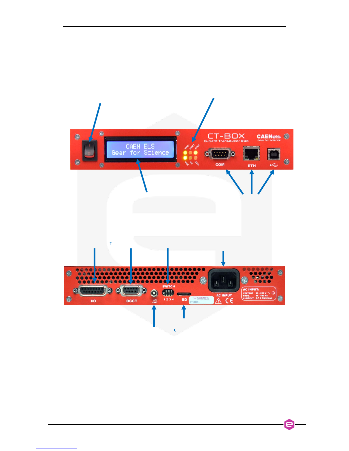
1.2 THE CT-BOX AT A GLANCE ....................................................................... 8
1.3 CT-BOX VERSIONS...................................................................................10
1.4 START OPERATION IN 5STEPS....................................................................12
1.4.1 Package Content ...................................................................................12
1.4.2 Connect the CT-BOX.............................................................................13
1.4.3 Turn On the CT-BOX ............................................................................14
1.4.4 CT-BOX Viewer Installation..................................................................14
1.4.5 Connect and Play..................................................................................15
1.4.5.1 Ethernet Communication...............................................................15
1.4.5.2 USB Communication.....................................................................15
1.5 START-UP CONFIGURATION .......................................................................17
1.5.1 Saved Configuration..............................................................................17
1.5.2 Desktop Configuration..........................................................................17
1.6 TEMPERATURE STABILIZATION...................................................................18
2. SOFTWARE COMMANDS...........................................................................19
2.1 COMMAND SYNTAX...................................................................................19
2.1.1 Data Representation..............................................................................22
2.2 BASIC COMMANDS.....................................................................................26
2.2.1 MODE Command..................................................................................26
2.2.2 GET Command......................................................................................28
2.2.3 GETT Command ...................................................................................29
2.2.4 ACQ Command.....................................................................................30
2.2.5 PRINT Command..................................................................................32
2.2.6 TS Command.........................................................................................33
2.2.7 FREQ Command...................................................................................34
2.2.8 ACQT Command...................................................................................35
2.2.9 VER Command......................................................................................36
2.2.10 CTBOX Command............................................................................37
2.2.11 DCCT Command..............................................................................38
2.2.12 PTURNS Command...........................................................................39
2.2.13 OFFSET Command...........................................................................41
2.2.14 STATUS Command............................................................................42
2.2.15 ERR Command.................................................................................43
2.3 ADVANCED COMMANDS ............................................................................45
2.3.1 ALARM Command ................................................................................45
2.3.2 SAVE Command....................................................................................48
2.3.3 SD Command........................................................................................49
2.3.4 TRG Command......................................................................................51
2.3.4.1 Triggered Acquisition....................................................................51
2.3.5 IP Command.........................................................................................53
2.3.6 MASK Command...................................................................................54
2.3.7 GATE Command...................................................................................54
2.3.8 PORT Command...................................................................................55
2.3.9 HWRESET Command............................................................................55

CT-BOX User’s Manual
ii
2.3.10 TIME Command................................................................................56
2.3.11 DATE Command ...............................................................................57
3. CONNECTORS AND INTERFACES...........................................................58
3.1 ETHERNET INTERFACE ...............................................................................58
3.2 USB INTERFACE ........................................................................................59
3.2.1 Firmware Upgrade................................................................................60
3.3 POWER CONNECTOR ..................................................................................62
3.4 I/O CONNECTOR ........................................................................................63
3.4.1 External Temperature Sensor................................................................64
3.5 DCCT CONNECTOR ...................................................................................65
3.6 ANALOG OUTPUT.......................................................................................65
3.7 SD-CARD SOCKET .....................................................................................66
4. TECHNICAL SPECIFICATIONS................................................................67
4.1 NOISE........................................................................................................68
5. MECHANICAL DIMENSIONS....................................................................69
6. APPENDIX .....................................................................................................71
6.1 LIST OF ERROR CODES...............................................................................71

CT-BOX User’s Manual
iii
Document Revision
Date
Comment
0.9
June 23th 2015
Draft release
1.0
January 28th 2016
First Release
1.1
December 23rd 2016
Address Changed
1.2
February 8th 2017
New technical
specifications added as
from recent tests
1.3
December 10th 2017
New features added
1.4
March 13th 2018
Data Representation
section corrected

CT-BOX User’s Manual
iv
Safety information - Warnings
CAEN ELS will repair or replace any product within the guarantee period if the
Guarantor declares that the product is defective due to workmanship or materials and
has not been caused by mishandling, negligence on behalf of the User, accident or any
abnormal conditions or operations.
Please read carefully the manual before operating any part of the instrument.
WARNING
Do NOT open the boxes.
CAEN ELS s.r.l. declines all responsibility for damages or injuries caused
by an improper use of the Device due to negligence on behalf of the User. It is
strongly recommended to read thoroughly this User's Manual before any kind of
operation.
CAEN ELS s.r.l. reserves the right to change partially or entirely the contents of this
Manual at any time and without giving any notice.
Disposal of the Product
The product must never be dumped in the Municipal Waste. Please check your local
regulations for disposal of electronics products.

CT-BOX User’s Manual
v
Read over the instruction manual carefully before using the instrument.
The following precautions should be strictly observed before using the CT-BOX
device:
WARNING
•Do not use this product in any manner not
specified by the manufacturer. The protective
features of this product may be impaired if it is
used in a manner not specified in this manual.
•Do not use the device if it is damaged. Before you
use the device, inspect the instrument for possible
cracks or breaks before each use.
•Do not operate the device around explosives gas,
vapor or dust.
•Always use the device with the cables provided.
•Turn off the device before establishing any
connection.
•Do not operatethe device with the cover removed
or loosened.
•Do not install substitute parts or perform any
unauthorized modification to the product.
•Return the productto the manufacturer for service
and repair to ensure that safety features are
maintained
CAUTION
•This instrument is designed for indoor use and in
area with low condensation.

CT-BOX User’s Manual
vi
The following table shows the general environmental requirements for a correct
operation of the instrument:
Environmental Conditions
Requirements
Operating Temperature
10°C to 40°C
Operating Humidity
30% to 85% RH (non-condensing)
Storage Temperature
-10°C to 60°C
Storage Humidity
5% to 90% RH (non-condensing)

CT-BOX User’s Manual
7
1.Introduction
This chapter describes the general characteristics and main features ofthe CT-BOX
digital measuring solution.
1.1 The CT-BOX Measuring System
The CT-BOX by CAEN ELS is a stand-alone digital measuring system designed
to measure DC and AC currents with high accuracy, wide-bandwidth, high precision
and extremely high stability.
The system is developed to be used with the CAEN ELS the < CT-series
current output DCCTs, allowing high performance measurements of currents up to
1000 A. The device integrates temperature-stabilized components as a burden resistor,
signal conditioning networks and a precision 24-bit ADC in order to have temperature
dependence lower than 1 ppm/K. The digital section interfaced to the ADC performs a
calibrated measurement in order to drastically reduce the non-ideal behavior thus
providing a very high accuracy. The ADC sampling frequency can be configured up to
100 kHz which allows the acquisition of high frequency components and fast current
transients for data analysis.
The CT-BOX is housed in a light, robust and extremely compact metallic box
that can be also installed in 1U –19” rack with the available optional mounting brackets.
The system is also equipped with a plug-and-play GUI acquisition software
package called CT-BOX-Viewer that allows controlling, configuring and acquiring data
from multiple units and via different interfaces. More information on the CT-BOX-
Viewer operation can be found on the corresponding software guide.

CT-BOX User’s Manual
8
1.2 The CT-BOX at a Glance
The CT-BOX unit and its I/O connections can be seen in the Figure 1 (front) and
in the Figure 2 (rear).
Figure 1: front view of a CT-BOX unit
Figure 2: rear view of a CT-BOX unit
The power switch, display, status led indicators and communication connectors
are placed on the front side of the CT-BOX unit. The power button is used to switch on
or switch offthe device. This switch does not fully disconnect the device from the mains
power supply. The display shows useful information like the mode of operation, current
Status LEDs
Power button
Communication interfaces:
RS232, Ethernet and USB
Display
I/O connector
SD-card
connector
AC input
connector
Analog output
CT-series head
connector
DIP-switch

CT-BOX User’s Manual
9
readings etc. In addition to the display there are also six LEDs that show the following
information:
LED name
Description
VDC+
Positive Voltage “Power good” LED:
turned ON indicates that the +15V supply is correctly regulated
VDC-
Negative Voltage “Power good” LED:
turned ON indicates that the -15V supply is correctly regulated
DCCT
DCCT presence LED:
turned ON indicates that the correct DCCT is connected
flashing indicates that the connected DCCT is not the calibrated one
turned OFF indicates that the DCCT is not connected or it is faulty
SD
SD operation LED
turned ON indicates that the SD card is in use
STAT
General status LED
turned ON (and OFF shortly) indicates that a fault status occurred
flashing indicates that the unit is working properly
ACQ
Acquisition LED
turned ON indicates that the unit is acquiring and elaborating the measured data
Table 1: Front LED description
All the communication connectors are present on the front panel. On the rear
side of the unit are placed the I/O connector, the CT-series DCCT Head connector,
analog output monitor, configuration DIP-switches, SD-card connector and the AC
mains input connector. The I/O connector is an expansion connector that allows to
connect an additional external temperature sensor, triggers and alarm. The CT-series
connector is used to connect the CT-BOX unit with its calibrated CT-series DCCT head.
The analog output monitor gives a voltage value, which is proportional to the measured
current (the analog monitor has worse accuracy respect to the digital acquisition). The
SD-card slot allows connecting an external SD-card to save measurement data (data-
logger mode) and the DIP switch is used for firmware update and start-up mode
configuration.
The AC power line input (extended range) is on the rear right side of the
enclosure.

CT-BOX User’s Manual
10
1.3 CT-BOX Versions
The CT-BOX unit is available in the following versions, depending on the
maximum current measuring range:
Product Code
Ordering Code
Description
CT-BOX-100
WCTBOX100XAA
100A Current Transducer Digital Box with Local Display
and Ethernet, USB, RS-232 Communication Interfaces
CT-BOX-150
WCTBOX150XAA
150A Current Transducer Digital Box with Local Display
and Ethernet, USB, RS-232 Communication Interfaces
CT-BOX-200
WCTBOX200XAA
200A Current Transducer Digital Box with Local Display
and Ethernet, USB, RS-232 Communication Interfaces
CT-BOX-300
WCTBOX300XAA
300A Current Transducer Digital Box with Local Display
and Ethernet, USB, RS-232 Communication Interfaces
CT-BOX-400
WCTBOX400XAA
400A Current Transducer Digital Box with Local Display
and Ethernet, USB, RS-232 Communication Interfaces
CT-BOX-600
WCTBOX600XAA
600A Current Transducer Digital Box with Local Display
and Ethernet, USB, RS-232 Communication Interfaces
CT-BOX-1000
WCTBOX1000XA
1000A Current Transducer Digital Box with Local Display
and Ethernet, USB, RS-232 Communication Interfaces
Table 2: CT-BOX models
In addition it is possible to order optional mounting brackets for standard 19-inch
cabinet installation as shown hereafter:
Figure 3: CT-BOX with mounting brackets for 1U –19” cabinet

CT-BOX User’s Manual
11
The ordering code for the additional mounting bracket is the following:
Product Code
Ordering Code
Description
CT-BOX-MB
WCTBOXMBXAAA
CT-BOX Mounting Brackets for 1U - 19" cabinet
installation
Table 3: CT-BOX optional mounting brackets

CT-BOX User’s Manual
12
1.4 Start Operation in 5 Steps
The CT-BOX can be operated straightforward following these simple steps.
1.4.1 Package Content
The CT-BOX bundle is composed of six different items. Please check that all the
listed elements are present upon receipt of the package.
①
②
③
④
⑤
Manuals
FAT Report
User’s CD
4-GB MicroSD card
⑥
The items shown are hereafter described:
①CT-BOX central unit;
②0-FLUCS DCCT transducer/head;

CT-BOX User’s Manual
13
③AC power cord;
④USB cable (type-A to type-B) and Ethernet cable (RJ-45 plugs);
⑤Connection cable between CT-BOX central unit and 0-FLUCS DCCT
transducer/head;
⑥User’s CD, Manuals, Factory Acceptance Test (FAT) and 4-GB MicroSD card;
The mounting brackets are optional and they need to be ordered separately (they
are included in the package at the time of delivery only if included in the order).
1.4.2 Connect the CT-BOX
Please connect the CT-BOX central unit ①to the AC power line with the
provided cable –i.e. item ③- as shown hereafter.
Figure 4: AC power cord connection
Connect the DCCT transducer/head ②to the rear connector of the CT-BOX
central unit ①with the dedicated cable (DE-9 to DE-9 cable –i.e. item ⑤).
Figure 5: Connection of the DCCT cable
Please be sure to secure the connector with the fixing screws on both ends of the
cable.

CT-BOX User’s Manual
14
1.4.3 Turn On the CT-BOX
Turn on the CT-BOX central unit ①by switching the power button on the front
panel of the unit to “1” –i.e. ON –position.
Figure 6: Power switch ON position
Once the device powers up, the display and LEDs should turn on and light up.
1.4.4 CT-BOX Viewer Installation
Install the CT-BOX Viewer software included in the User’s CD (item ⑥) or
download the latest version from the corresponding product page on CAEN ELS
website (www.caenels.com). Please keep software up to date by checking for new
releases periodically.
Figure 7: CT-BOX Viewer software application

CT-BOX User’s Manual
15
Please refer to the “CT-BOX Viewer - Quick Start Guide” to check all features
and capabilities of the control software.
1.4.5 Connect and Play
There are two suggested ways to communicate with the CT-BOX central unit,
using the provided USB cable or a standard Ethernet connection. Both of them are
described hereafter.
1.4.5.1 Ethernet Communication
Connect a standard Ethernet cable ④between an external PC and the CT-BOX
central unit ①.
Figure 8: Ethernet connection
Follow the instructions and communication settings presented in the section
“Ethernet Interface” hereafter in this document.
1.4.5.2 USB Communication
Connect the USB cable (type-A to type-B) provided in the package (item ④)
between an external PC and the CT-BOX central unit ①.
Figure 9: USB connection

CT-BOX User’s Manual
16
Follow the instructions and communication setting presented in the section “USB
Interface” hereafter in this document.

CT-BOX User’s Manual
17
1.5 Start-Up Configuration
The CT-BOX unit can be configured to start-up (after a power cycle) with two
different configurations:
-Saved configuration;
-Desktop configuration.
Please note that these two alternate configurations are only valid for start-up and
they do not affect the other functionalities of the unit in any manner. These start-up
modes can be set by a DIP switch placed on the rear side of the CT-BOX enclosure.
1.5.1 Saved Configuration
The CT-BOX starts with the last saved configuration that was configured to the
device. The position of the DIP switch #4 of the rear panel needs to be set as shown
hereafter (HIGH position):
Figure 10: Saved Configuration at start-up
The device will be configured directly at start-up with the last configuration –e.g.
Data-logger or Oscilloscope mode, all other parameters. This allows to starting up the
device with the last configuration that was set by the user.
1.5.2 Desktop Configuration
The CT-BOX starts with a standard configuration if the position ofthe DIP switch
#4 of the rear panel is set as shown hereafter (LOW position):

CT-BOX User’s Manual
18
Figure 11: Desktop Configuration at start-up
This configuration is extremely useful when there is the need to use the CT-BOX
as a simple readout indicator of a current that needs to be measured as it could be in
cases of direct measurement on the field or in laboratory desktop setups.
When configured and starting up in this Desktop mode the CT-BOX does not
need any PC to be connected and it indicates the current readings directly on the display
placed on the front side (as it gets internally configured as Data-Logger at 1-Hz
acquisition frequency).
1.6 Temperature Stabilization
The CT-BOX unit has internal temperature-stabilized sections that allow
obtaining almost negligible temperature dependence of the measurements. Dependence
of the measurements from external ambient temperature are kept the best-in-class for
this type of instruments and below 1 ppm/FS (FS = Full scale), equivalent to < 0.0001
%/FS.
Being the thermal stabilization a physical slow process by nature, an initial
amount of time of 30 minutes is needed in order to be within the internal limits. All
specifications of the unit are guaranteed after this initial period.
The CT-BOX unit is then continuously monitoring the temperature in the critical
sections and the correct operation –i.e. temperature stabilization –is indicated by the
status of the bit #6 of the internal Status Code (“ADC Temp OK”). Further information
on this status code are presented hereafter in the document.
Table of contents
Popular Measuring Instrument manuals by other brands

Kele
Kele KDP2M Series installation guide

PCB Piezotronics
PCB Piezotronics PCB-339A31 Installation and operating manual

Agilent Technologies
Agilent Technologies 8614 B Series user guide

PPS
PPS PPS28 user manual

Safeside
Safeside R-3D2 Series Installation and operating instructions

PHYWE
PHYWE Cobra4 operating instructions