Cairn MultiSplit V2 User manual

Horizontal (H) and Vertical
(V) image separation
controls
H and V adjustment for
cube 3
H and V adjustment for
cube 2
Output port
Camera mounting thread
Input port
Rectangular aperture adjusters
MultiSplit V2
Manual
The MultiSplit is calibrated and QC’d prior to delivery, however some alignment is required upon initial setup
using the calibration cubes provided (each containing a 50% mirror). This manual provides instructions for
mounting the unit on your microscope and basic alignment to project four identical images onto your camera
chip. A more detailed technical manual can also be provided upon request.
For the purposes of this manual, all text in bold blue is referenced on subsequent images.
1) Mounting to your microscope
1. The MultiSplit is supplied with four detached support feet, these should be screwed into the mounts on the
base of the unit prior to setup. A blue locking ring allows each support leg to be locked off at the correct
position.
2. Screw your microscope c-mount onto the input section of the MultiSplit and attach to your microscope
frame.
3. Adjust the support feet until the unit is level (a spirt level is recommended).
4. Initial setup is completed without your imaging camera mounted on the unit, so for the time being, place
your camera safely to one side.
2) Key Controls
The following images show the MultiSplit panels, which will be referenced during setup of the unit.
2.1) MultiSplit Panels
Figure 1: MultiSplit top panel

Support leg
Cube 1 magnetic door cover
Cube 1 H and V controls
Auxiliary drop-
in positions (TT)
Cube 2 magnetic door cover
Auxiliary drop-in positions (TR)
Cube 3 magnetic door cover
Auxiliary drop-in positions (RR)
Auxiliary drop-in positions (RT)
Figure 2: MultiSplit side panel 1
Figure 3: MultiSplit side panel 2

Knurled blue handle
(Cube 1 only)
2.2) Defining Field of View
An adjustable rectangular aperture (or diaphragm) precisely defines the region of interest reaching the camera
sensor. This region is then reflected by both internal mirrors within the unit and dichroic mirrors placed in the
light paths to project this identical region into four quadrants. *
* Please note, the MultiSplit has been designed specifically to generate four images projected into quadrants –
the internal mirrors are not designed to be used in any other format (e.g. for two images side by side, or a single
full field ‘bypass’ image)
1. Slide the two aperture adjusters (one horizontal, the other vertical) to define your region of interest.
2. This region can be locked in place once alignment is complete by turning the aperture handles.
3. Once your camera has been mounted following initial alignment, the aperture edges should be in sharp
focus in your image when partially closed. If not, please contact us (tech@cairn-research.co.uk) for further
advice and we will be happy to advise depending upon your hardware setup.
Figure 4: Rectangular Aperture
2.3) Filter cubes and cradles
The MultiSplit is supplied with three labelled calibration cubes to aid setup, each containing a 50% / 50% mirror.
Two cube cradles are also supplied and are essential to house cubes 2 and 3 at a 90-degree angle within the unit.
Figure 5: Cairn filter cube

Each cube will be labelled – Cube 1 includes a knurled blue handle and is inserted in the position closest to the
rectangular aperture, once the Cube 1 magnetic door cover has been removed.
Cubes 2 and 3 (both the calibration cubes and Cairn filter cubes) will have this blue handle removed and once
inserted into the cube cradles as shown in figure 6, the cradle can be inserted to positions 2 and 3 respectively.
Please ensure the cube cradles sit flush within the unit and are not angled – internal magnets will ensure the
cradle locates correctly.
Figure 6: Fitting cairn cubes 2 and 3 into the cube cradle
Figure 7: Cube cradle (containing cube 2) being inserted into the unit

Calibration tool
Camera mounting thread
3) Initial alignment
For initial setup, we suggest mounting the MultiSplit to your microscope without your imaging camera. The four
quadrants can then be roughly aligned in the correct configuration, which avoids issues with some imaging
cameras flipping the image in software. Final adjustments can then be made with the camera in place.
To aid this initial setup, a piece of paper held over the camera mounting thread is sufficient to observe the
quadrants as each cube is added to the unit.
Figure 8: Camera mounting thread minus imaging camera
3.1) Light path diagram
It is pertinent at this point to consider the internal light path within the MultiSplit and familiarise yourself with
the image nomenclature.
‘T’ refers to transmitted and similarly, ‘R’ refers to reflected.
Each of the four images is labelled accordingly:
Image reference Related cube number Nominal ‘colour’ of image
TT No cubes in unit Red
RT Cube 1 Green
TR Cube 2 Yellow
RR Cube 3 Blue

Figure 9: MultiSplit light path diagram
3.2) Positioning the primary image (TT)
1. Turn up your brightfield microscope light source to maximum and divert the light to the relevant side port.
2. Ensure no filter cubes are within the MultiSplit unit.
3. Hold a small piece of paper over the camera mounting thread.
4. Close the rectangular aperture down until one small square is visible through the piece of paper (~one
quarter of the whole aperture).
5. Re-position this image using the horizontal (H) and vertical (V) image separation controls show in Figure 1.
6. When looking through the piece of paper towards the microscope from the output of the MultiSplit, move
the TT image to the bottom left corner.
3.3) Positioning the reflected images (RT, TR and RR)
Once TT is in the correct quadrant, the remaining images can then be positioned in turn.
Cube 1: Image RT
1. Insert the calibration cube labelled Cube 1 into its correct position (note, this is the cube with the knurled
blue handle) – this will cause image RT to appear.
2. Replace the Cube 1 magnetic door cover.
3. Using the 1.5mm Allen key provided, re-position this image using Cube 1 H & V controls (Figure 2) on the
cube door. This mechanism tips and tilts the calibration cube (50% / 50% mirror), giving a smooth movement
to reposition this image.
4. When looking through the paper towards the microscope from the output of the MultiSplit, move the RT
image to the bottom right corner.
Cube 2: Image TR
1. Insert the calibration cube labelled Cube 2 into the cube cradle according to Figure 6.
2. Insert the cube and holder into cube position 2 – this will cause image TR to appear.
3. Replace the Cube 2 magnetic door cover.

No cubes (TT) Cube 1 (RT)
Cube 2 (TR) Cube 3 (RR)
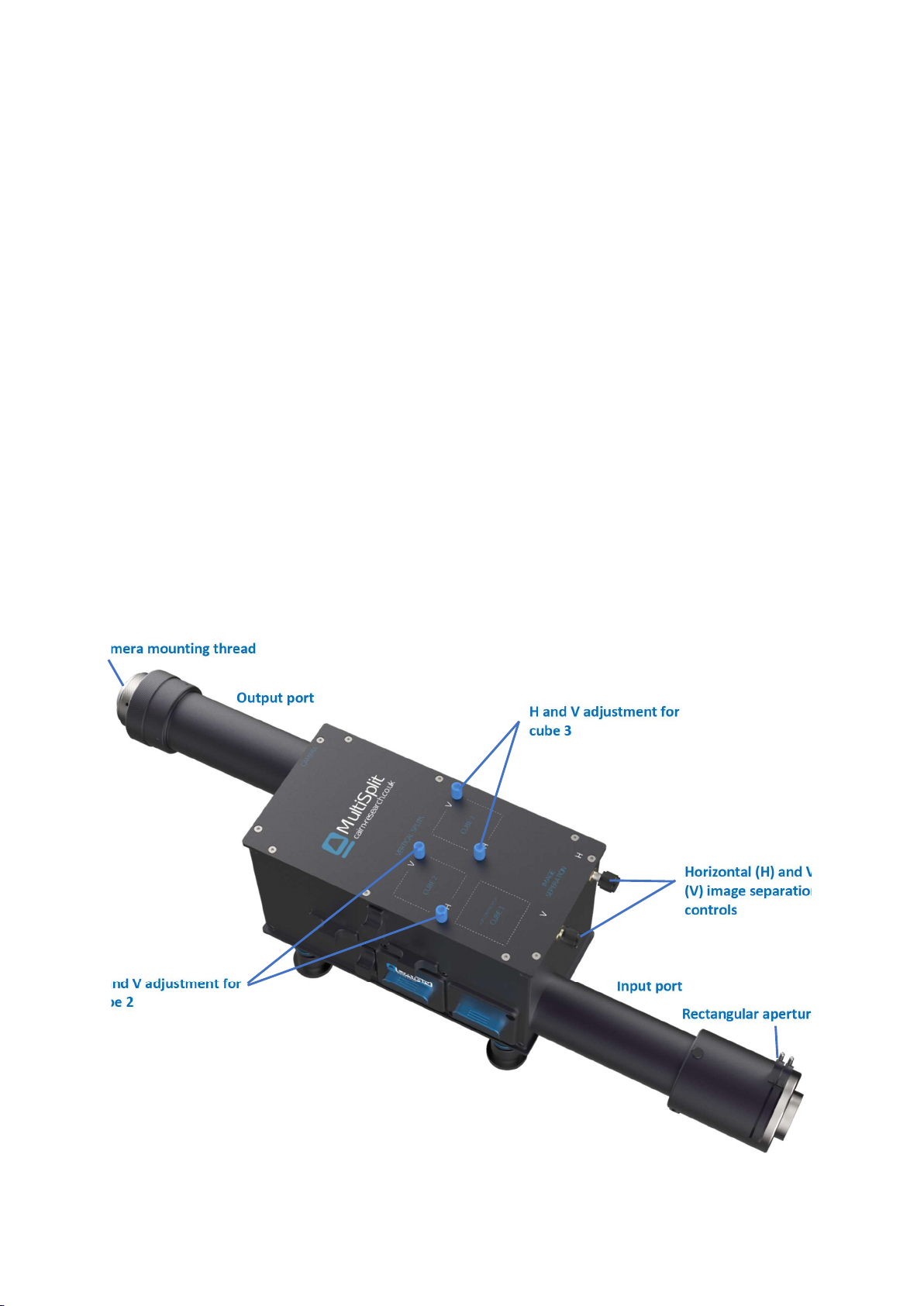
4. Using the blue thumb screws labelled H and V adjustment for cube 2 in Figure 1, re-position this image to
the correct quadrant.
5. When looking through the piece of paper towards the microscope from the output of the MultiSplit, move
the TR image to the top left corner.
Cube 3: Image RR
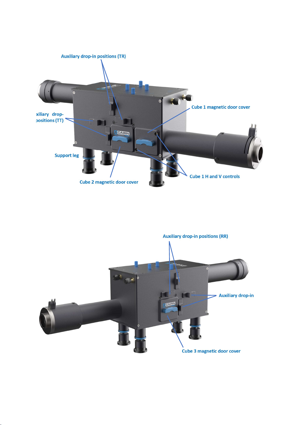
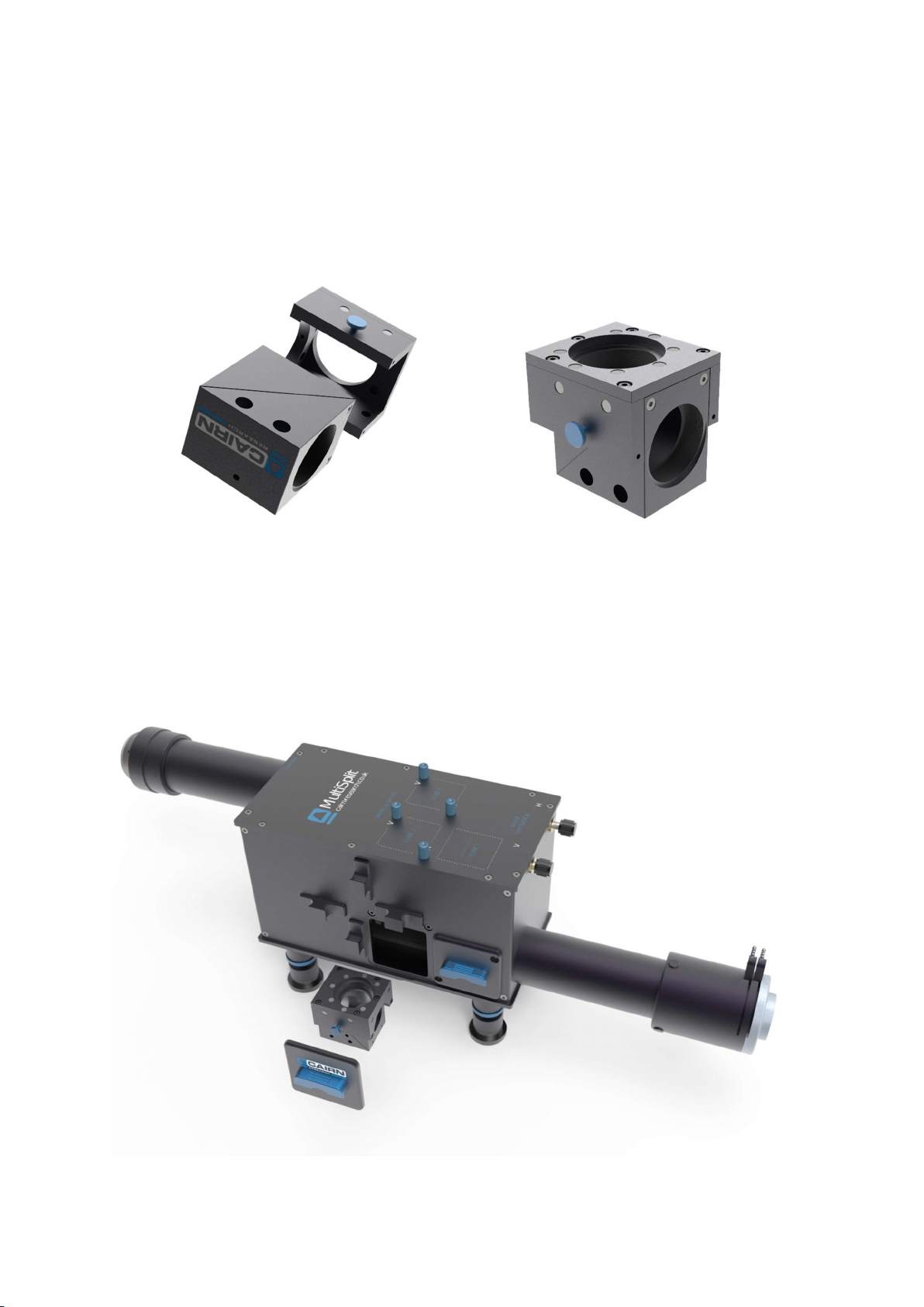
1. Place the calibration cube labelled Cube 3 into the remaining cube cradle according to Figure 6.
2. Insert the cube and holder into cube position 3 – this will cause image RR to appear.
3. Replace the Cube 3 magnetic door cover.
4. Using the blue thumb screws labelled H and V adjustment for cube 3 in Figure 1, re-position this image to
the correct quadrant.
5. When looking through the piece of paper towards the microscope from the output of the MultiSplit, move
the RR image to the top right corner.
With all three calibration cubes in place, the four quadrants projected onto the piece of paper should be:
Figure 10: Images projected onto the paper over the camera aperture with all three cubes in place.
Note the quadrant colours are for illustrative purposes only and indicate the image wavelength from high to low
(Red > Yellow > Green > Blue).
4) Obtaining a split image on your camera
As the four quadrants are now in the correct position, your imaging camera can now be attached to the
MultiSplit.
The silver knurled camera mounting thread on the output tube can be rotated to secure the camera, whilst also
ensuring any cables connected do not get tangled. Once the camera is fully screwed onto the c-mount, ensure
it is level and stable. The four small nylon tipped grub screws on this silver section can be tightened using the
1.5mm Allen key supplied to give extra rigidity.
Our support jack is highly recommended as an additional accessory to ensure the camera is fully supported on
the output port.
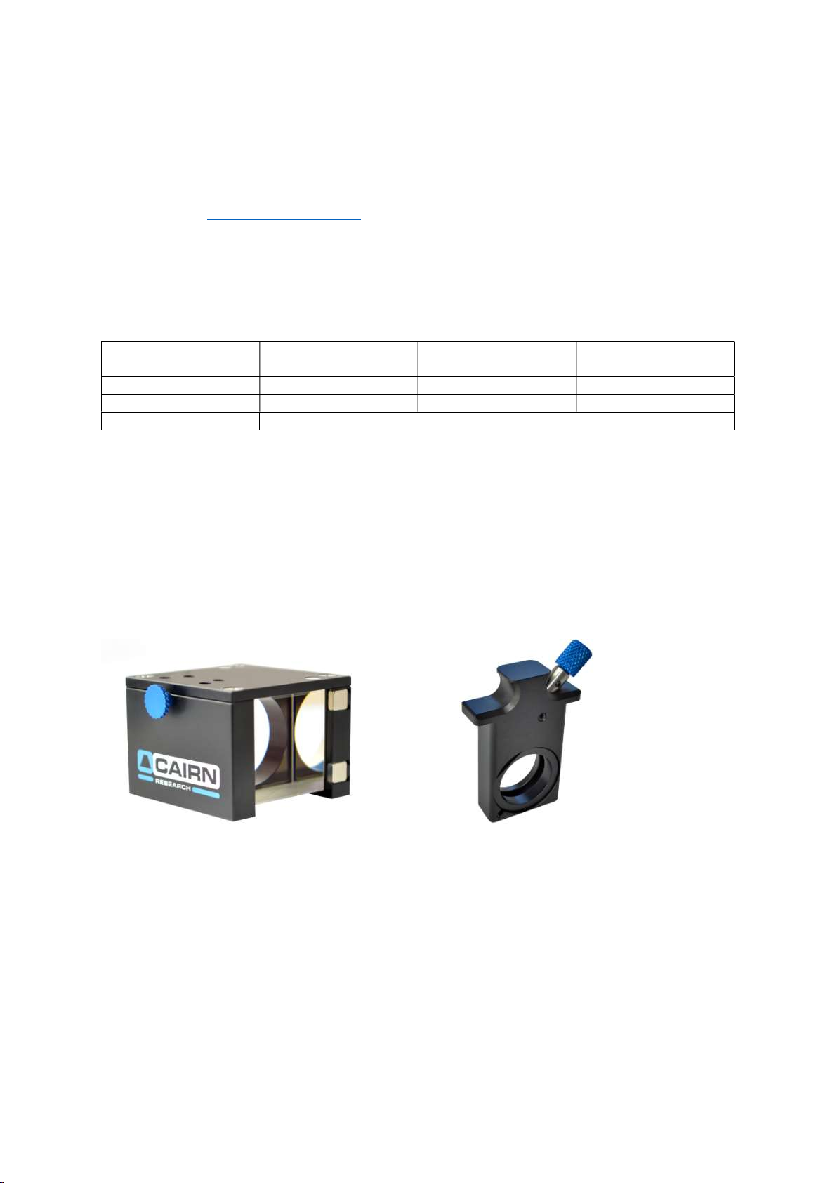
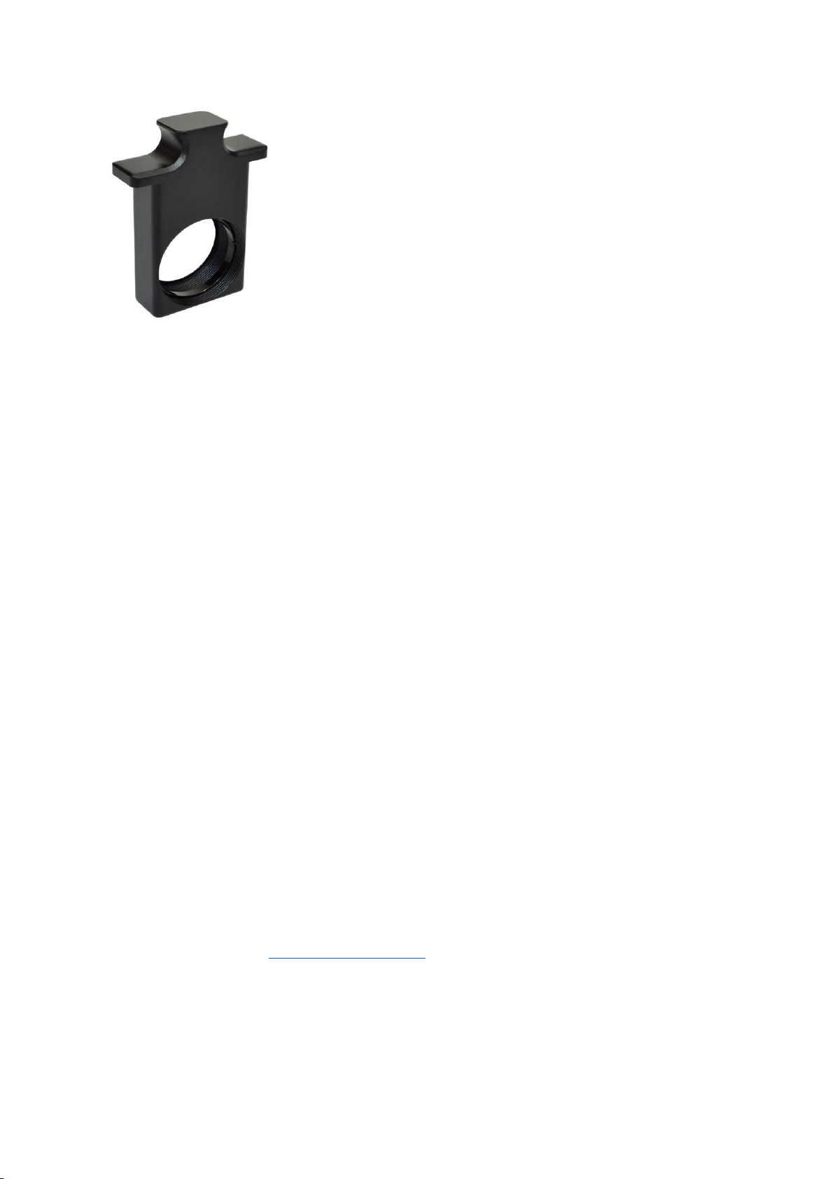
It’s useful at this stage to familiarise yourself with each of the four channels on your imaging camera. This can
be easily achieved using the shutter blanking plate supplied with each unit. This tool will block the light path in
the corresponding channel (see figure 14 and 15 for the auxiliary positions for each channel). The shutter
blanking plate can also be used during operation should one or more of the channels not be required.
TT
RR TR
RT

5) Filter cube assembly
Often MultiSplit units are supplied with populated filter cubes, however (if required), these can be installed using
the guidance notes below.
5.1) Installing dichroic mirrors and emission filters
As UK distributors, we have worked very closely with Chroma to develop a dichroic mirror range for use in our
image splitters with minimal image distortion. As a result, we only recommend the Chroma Ultra-Flat (UF-2)
2mm thick dichroic mirror range.
The Cairn Filter Cube accepts 26mm x 38mm x 2mm dichroic mirrors and 25mm ring mounted emission filters.
Other dichroic mirrors will fit; however, they may not be optimal. We are of course happy to provide filter and
dichroic mirror advice for your specific application, so please get in touch.
Figure 11: Installing dichroic mirrors and emission filters in the Cairn Filter Cube

5.2) Filter cube positioning
When using the MultiSplit to image four colours simultaneously, the example below provides guidance for
dichroic mirror and filter cube positioning according to the internal light path as shown in Figure 9.
In this example, four laser lines are used for excitation, however, other light sources (such as LED’s) can be used.
Please contact us (tech@cairn-research.co.uk) if you would like specific filter advice for your requirements.
Laser lines:
405nm
488nm
561nm
640nm
Cube number Dichroic mirror Emission filter
(transmitted)
Emission filter
(reflected)
1 T565lpxr-UF2 None None
2 T635lpxr-UF2 ET 700/75m ET 600/50m
3 T495lpxr-UF2 ET 525/50m ET 445/58m
5.3) Polarisation (anisotropy) studies
For polarisation experiments, a Cairn filter cube with an integrated polarising beamsplitter cube* is also available
as an additional accessory. In addition, a rotating 18mm polariser is available to act as a ‘clean-up’ for the
reflected S wave.
The MultiSplit can therefore be configured for a mixture of experiments, such as two-colours in two different
polarisation states.
* Please note the polarising beamsplitter cube is very fragile!
Figure 12: Polarisation components available as additional accessories
5.4) Accessory kits: Neutral Density and Corrector Lenses
Additional accessories are available upon request, which are housed in auxiliary drop-in holders and inserted
into each of the four light paths where required. Blank covers are provided as standard in the absence of these
drop-ins.

Figure 13: Auxiliary drop-in holder and retaining ring
Neutral Density kit
A series of four neutral density filters are useful if one (or more) of the channels is disproportionally brighter
than another.
03GN25: 50% Transmittance
05GN25: 32% Transmittance
06GN25: 25% Transmittance
10GN25: 10% Transmittance
Corrector lens kit
If one or more of the channels looks out of focus in comparison to others, it may be due to chromatic aberration.
This results when the focal length changes depending upon the emission wavelength and is predominantly
introduced by the objective lens. When imaging multiple wavelengths simultaneously, the phenomenon is
observed using the MultiSplit, rather than being caused by it.
Our corrector lens kit provides a series of weak crown glass lenses, often used by trial and error for correcting
the unwanted effect. We recommend starting with the weakest lens (longest focal length) in the out of focus
channel.
IO137: Focal length 1346mm
IO138: Focal length 2019mm
IO139: Focal length 4034mm
IO140: Focal length 5000mm (1” holder required)
IO141: Focal length 10,000mm (1” holder required)
6) Multi-depth Imaging
The MultiSplit has two auxiliary drop-in positions for each channel, accessible from the outer panels of the unit.
The corrector lens kit described in section 5.4 can be used in these positions for two purposes: a) chromatic
correction or b) to deliberately shift the focal plane for multi-depth imaging.
For precise focal plane shifting, we have a spreadsheet available to estimate the best focal length lens (if
available). Please contact us (tech@cairm-research.co.uk) for this further detail and we will be happy to advise
for your application.
The optimum positions for shifting the focal plane in each channel is indicated below.

Cube 1
Cube 2
Corrector lens position: TT
Corrector lens position: TR
Cube 3
Corrector lens position: RT
Corrector lens position: RR
Figure 14: Corrector lens positions for TR and TT
Figure 15: Corrector lens positions for RT and RR

7) Analysing multi-channel data
For overlaying up to four channels ‘live’ or with a saved image, we have written a Micro-Manager plugin,
available via our Software page on our website: (https://www.cairn-research.co.uk/support/software/).
1. Ensure you have a compatible version of Micro-Manager installed (Beta or Gamma nightly builds are
compatible).
2. Download the Cairn_MultiSplit_3.jar file and paste into the mmplugins folder in the root Micro-Manager
directory on the C drive.
For example: C:\Program Files\Micro-Manager-2.0.0-gamma1_20190722\mmplugins
3. Obtain a live camera image of your four split channels, or alternatively open your saved Tiff file in Micro-
Manager.
Please note, when overlaying the channels post acquisition, the original image must have been saved in
Micro-Manager, the overlay plugin will not work if the file was saved in another software package.
4. Click on Plugins > On-The-Fly Image Processing > Cairn Multi Split V3
5. Ensure the Plugin is ticked as ‘Enabled’ and ‘Snap/Live’ in the On-The-Fly Processing Pipeline dialogue box.
6. Within the ‘Cairn Multi Split’ dialogue box, ensure the tab is set to ‘OptoSplit’ and the channel option is set
to ‘4 Channels’

7. Draw a rectangular region of interest (using ImageJ) around your longest (red) wavelength channel. Click on
‘Select Channel 1’.
8. Move the same region of interest to the ‘green’ channel and click ‘Select Channel 2’.
9. Similarly, repeat for the Blue (Channel 3) and Yellow (Channel 4). A four-colour composite overlay will now
be displayed, with individual intensity histograms for each channel.
10. Each individual image can be nudged using the arrows within the Multi Split window, then saved once
complete.
If you have any questions during installation or use of the MultiSplit, please do not hesitate to contact our Tech
Support Team (tech@cairn-research.co.uk)
Table of contents
Other Cairn Media Converter manuals