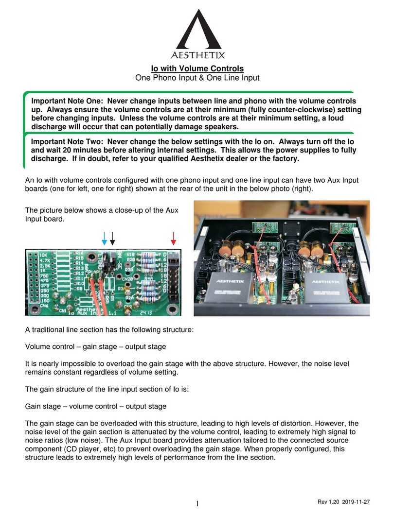
Caledonian Audio Phono Classique User manual

Assembly Manual
Phono Classique
Version 1.0
Caledonian Audio

!
2!
Version History
Version
Date
Changes
1.0_draft
3 August 2020
Initial creation
1.0
18 October 2020
Reviewed and corrected.

Caledonian!Audio!
Phono%Classique%Assembly%Manual%
3%
!
!
3!
WARNING – DANGER OF SERIOUS INJURIES AND LOST OF LIFE
The work conducted here deals with high-level voltages. It should only be
conducted by qualified personals.
Please be aware that capacitors can hold charges for a long time, and they
should be properly discharged prior to any work.
The 6.3V or 12V terminals are rated in relation to another voltage reference
level, but in reality, the potential difference between the 12V (as an example)
and ground earth might be anywhere up to 400V. So, please treat any 6.3V or
12V terminals with extreme care.
Caledonian Audio will not be held responsible to any incident caused
directly or indirectly by any work or product mentioned in this manual.
This document should only be used as a guide and you should always
refer and discuss with qualified electricians or individuals to verify the
content before starting any pieces of work.

!
4!
Table of contents
1 Introduction ............................................................................................... 7
1.1 Scope of this document ..................................................................... 7
1.2 Assumptions ...................................................................................... 7
1.3 Tools / parts needed: ......................................................................... 7
1.4 Assembly Instructions ....................................................................... 8
1.5 Disclaimer .......................................................................................... 8
2 PCBs Preparation ..................................................................................... 9
2.1 Integrated Power Supply PCB ......................................................... 10
2.1.1 Resistors .................................................................................. 11
2.1.2 Capacitors ................................................................................ 12
2.1.3 Diodes ...................................................................................... 12
2.1.4 12VDC Voltage Regulator and Heatsink .................................. 13
2.1.5 Common Mode Choke – EMI filter ........................................... 14
2.2 Phono preamp PCB ........................................................................ 16
2.2.1 Valve Holders ........................................................................... 16
2.2.2 Soldering Resistors .................................................................. 17
2.2.3 Soldering Capacitors ................................................................ 18
3 Mounting Parts on The Mounting Plate .................................................. 19
3.1 IEC Power Socket ........................................................................... 21
3.2 RCA Connectors ............................................................................. 23
3.3 Power Switch ................................................................................... 23
3.4 PCBs ............................................................................................... 24
3.5 Transformers ................................................................................... 25
3.6 Ground Lift (Isolator) Circuit (Not Included) ..................................... 27
3.7 Ground Lug ..................................................................................... 27
4 Wiring / Connecting Cables .................................................................... 28
4.1 Power Cables .................................................................................. 28
4.1.1 Safety Earth ............................................................................. 28
4.1.2 IEC Socket to the Power Switch .............................................. 28
4.1.3 Main Switch to Transformers ................................................... 29
4.1.4 Transformer 1 To Heater Power Supply .................................. 32
4.1.5 Transformer 2 To Main Power Supply ..................................... 32
4.1.6 Main Power Supply to Phono Board (B+) ................................ 32
4.1.7 Power Supply Board GND Connection .................................... 33
4.1.8 Heater Tap Jumper Connection ............................................... 33
4.1.9 Heater Power Supply to Heaters (12.6VDC) ............................ 33
4.2 Audio Cables ................................................................................... 34
4.2.1 Left Audio In ............................................................................. 35
4.2.2 Right Audio In ........................................................................... 35
4.2.3 Left Audio Out .......................................................................... 35
4.2.4 Right Audio Out ........................................................................ 36
4.2.5 Star Earth ................................................................................. 36
5 Powering Up for The First Time .............................................................. 37
6 Questions / Support ................................................................................ 39
7 Appendix ................................................................................................. 40
I. Screws / Nuts / Bolts Sizes ............................................................. 40
II. Index of All Fixings Used In A Kit .................................................... 42
III. Amplifier PCB Components ............................................................. 42
Caledonian!Audio!
Phono%Classique%Assembly%Manual%
5%
!
!
5!
IV. Integrated Power Supply PCB Components ................................... 43
V. Wiring Diagram – UK / Europe (230VAC) ....................................... 45
VI. Wiring Diagram – US (115VAC) ...................................................... 46
VII. Schematics - Phono Amp Circuit ..................................................... 47
VIII. Schematics – Power Supply Circuit ................................................ 48
Figure 1 Integrated power supply PCB .......................................................... 11
Figure 2 Resistors on the power supply PCB ................................................ 12
Figure 3 Power supply PCB with resistors, capacitors and diodes installed. 13
Figure 4 - Supplied heatsink .......................................................................... 14
Figure 5 - Power supply PCB with the common mode choke installed ......... 14
Figure 6 - Power supply PCB with heatsink attached to the voltage regulator
................................................................................................................ 15
Figure 7 - Another view of the completed power supply PCB ....................... 15
Figure 8 - Phono amp PCB with valve sockets installed. Note that valve
sockets might differ to the ones supplied in your kit ............................... 17
Figure 9 - Phono amp PCB with all resistors installed ................................... 18
Figure 10 - Phono amp with capacitors installed ........................................... 19
Figure 11 - mounting plate - bottom view ...................................................... 20
Figure 12 - Placement of all parts and PCBs on the mounting plate ............. 21
Figure 13 - IEC socket mounted .................................................................... 22
Figure 14 - IEC socket mounted - front view - note the orientation ............... 22
Figure 15 - RCA connectors installed - viewed from the top ......................... 23
Figure 16 - Main power switch secured to the mounting plate ...................... 24
Figure 17 - PCBs mounted using the standoffs ............................................. 24
Figure 18 - The orientations of the PCBs ...................................................... 25
Figure 19 - Transformers mounted onto the plate ......................................... 26
Figure 20 - Heater transformer ...................................................................... 26
Figure 21 - Main transformer ......................................................................... 27
Figure 22 - Ground safety earth from IEC socket wired to the chassis and
secured by a shakeproof washer and insert lock nut ............................. 28
Figure 23 - Power cables connecting the live and neutral terminals on the IEC
socket to the main power switch ............................................................. 29
Figure 24 - Two pairs of cables connecting the output from the power switch,
to the two transformers ........................................................................... 30
Figure 25 - Primary windings of Transformer 2 connected to the mains AC
voltage from the switch. Please note the wiring for 230VAC system. .... 31
Figure 26 - Primary windings of Transformer 1 connected to the mains AC
voltage from the switch ........................................................................... 31
Figure 27 - Image showing B+ connection between the Integrated Power
Supply PCB and the phono PCB ............................................................ 32
Figure 28 - Image showing the terminals for the valve heaters (circled in red) -
please note the polarities of these terminals do not matter .................... 33
Figure 29 - Powering the valve heaters from the integrated power supply PCB
................................................................................................................ 34
Figure 30 - Valve heaters connected in parallel to the power supply PCB .... 34
Figure 31 - Wiring diagram focusing on the audio level lines and star earth
connection. Note that screen cables are used and only one end of the
screen is connected to ground. .............................................................. 35

!
6!
Figure 32 - Audio level cables and star earth ................................................ 36

Caledonian!Audio!
Phono%Classique%Assembly%Manual%
7%
!
!
7!
1 Introduction
Congratulations and thank you for purchasing this kit. This guide enables
readers to build and assemble the Phono Classique DIY Amplifier kit.
If you have any questions, please get in touch with us at:
We also value any feedback that you might have after going through this
document.
1.1 Scope of this document
This document is applicable for setting up the Phono Classique DIY Amplifier
kit
of the following versions:
1. Phono amp PCB VC
2. Integrated power supply PCB Rev:2b
3. Classique – Phono – Aluminium Mounting Plate
Other versions or revisions might be applicable but please check with us first.
1.2 Assumptions
1. Only parts and devices, which are part of this kit, are used in the build.
Caledonian Audio will not support usage of any other parts or
components other than supplied and mentioned by us in this document
2. A compatible aluminium mounting board is used
3. Reader is capable of performing wiring / soldering and understands risks
of fatal level of voltages
1.3 Tools / parts needed:
• Screwdrivers (multiple sizes)
• Long nose pliers
• Soldering iron (with solders etc.)
• Wire cutters
• Wire strippers
• Heat shrinks
• Cables / wires for hookups and power lines (please see wiring diagram
for exact ratings and colour codes
• Fuse – 5x20mm – 250VAC – 0.5A slow blow for UK/EU version and 1A
for US version. (This is to be added to the fuse slot in the IEC socket)

!
8!
1.4 Assembly Instructions
The general assembly plan is as follows:
1. Prepare all PCBs (Power supply and phono amplifier board)
2. Mount 2 power transformers onto mounting board
3. Mount all connectors (power and audio)
4. Install power cables
5. Install hookup cables
Components and devices shown in this manual might be slightly different
compared to ones included in the kit.
1.5 Disclaimer

Caledonian!Audio!
Phono%Classique%Assembly%Manual%
9%
!
!
9!
2 PCBs Preparation
It would be advisable that you line up all supplied components in front of you
to make sure that you know what they are.
Refer to the supplied part list. All your electronic components should have a
label either on the packaging or on the part itself.
It is also a good idea to double check the values of the resistors against the
parts list, just in case there has been an error during packaging.
Always make sure that you are working on a clean and organized workplace.
You will be working with components which are relatively small, and it is easy
to drop them on the floor and never to be found again, so please be careful.
Before we start stuffing the board with components and start the soldering
process, there are a number of items to consider:
There are some cable connections that we will have to make on to the PCBs.
You will have to decide if you are to use PCB terminal blocks or to solder cables
directly into the through hole pads.
In some parts of the work, you will be connecting cables onto PCBs. You can
either use PCB terminal blocks or solder the cable directly onto the PCBs.
Terminals blocks are handy and very forgiving (if you make a mistake then just
unscrew and detach the cables again).
On the other hand, soldering a cable straight into the hole is much more
permanent and more reliable as the screws can be loosen within time.
If you purchased a complete kit, you will be supplied with some terminal blocks
for the following connections:
Integrated Power Supply PCB:
1. 12VDC out (+ and zero)
2. B+ DC out (+ and zero)
3. High voltage AC in
4. Low voltage AC in
5. Another terminal to connect between 12VDC out and heater tap
Phono amplifier PCB:
1. B+ DC in (+ and zero)
2. 2 x audio interface (in+, out+ and g)
We will not be using PCB terminal block on this manual for the sake of having
a clearer images and documentation.

!
10!
Familiarize yourself with the schematics and the wiring diagram. Understanding
the circuit will help you to build this phono amplifier with confidence and
minimize risks of getting it wrong.
Study the wiring diagram and maybe try to visualize how your build before
actually doing it.
IMPORTANT NOTES ON HEATSINK AND VOLTAGE REGULATOR:
If you are to use the supplied heatsink (HS1) (for the 12VDC regulator chip), it
will be a good idea to attach the regulator chip (U1) onto the supplied heatsink
first before soldering the chip onto the PCB.
This enables you to correctly align the hole on the chip with the mounting hole
on the heatsink itself.
If you solder the chip onto the PCB first (without having it mounted on the
supplied heatsink), depending on the height of the legs inserted into the holes,
you might have some alignment issue later. So, please bear this in mind.
Once all preparations have been done, you can then start with stuffing and
soldering process.
2.1 Integrated Power Supply PCB
The integrated power supply PCB is responsible for converting AC voltages into
DC voltages for the phono amplifier board and the heater filaments for the three
valves.
The board is physically divided into two parts by an imaginary line in the middle
of the board. The top half is for managing the linear high voltage (B+) power
supply board and the bottom half is the regulated 12VDC. (The output is
actually 12.6VDC). See Figure 1 - Integrated power supply PCB.

Caledonian!Audio!
Phono%Classique%Assembly%Manual%
11%
!
!
11!
Figure 1 - Integrated power supply PCB
2.1.1 Resistors
Start with placing and soldering all resistors on the board. Figure 2 Resistors
on the power supply PCB displays all resistors and their purposes.
Resistor
Purpose
Note
R1, R2,
R3
Dropper
resistor
Place and solder them standing up (vertically).
R4, R5
Voltage divider
network
R4, R5 and C5 forms a voltage divider network
which is used as a reference point to raise the
12VDC heater filament
R6
Bleeder (see
note)
Do not populate R6.
R6 is there to enable you to add a bleeder
resistor as an alternative to the voltage divider
network (R4, R5 and C5 forms a voltage divider
network which is used to raise the 12VDC heater
filament).
Since we will be using the voltage divider
network, we no longer need to populate R6.
R7
12V line
dropper
Please use a wirelink for R7.

!
12!
R7 is there to enable you to lower the voltage (if
necessary) before it gets into the voltage
regulator.
If you find that the later stage that the voltage
going into the regulator is too high (perhaps due
to local fluctuation of AC voltage coming into
your property) and the regulator is doing too
much of work ramping it down to 12VDC, then
you can ease the work of the regulator a little bit
by lowering it before it goes into the regulator.
However, for now, you can just use a wire-link.
Figure 2 Resistors on the power supply PCB
2.1.2 Capacitors
Once all the resistors are done, move on to the capacitors.
Please note that ALL electrolytic capacitors have to have the correct polarities
on the PCB. So, before soldering them onto the board, make sure that they are
correct. The electrolytic capacitors are:
• C1
• C2
• C3
• C4
• C5
• C7
• C8
• C9
• C11
• C12
As usual, follow the drawing on the PCB silkscreen which indicates the
polarities of the capacitors. Place and solder other capacitors as well.
2.1.3 Diodes
Please make sure that you get the correct polarities for:
1. D1, D2, D4, D5 – these are Schottky diodes in TO-220 format which form
the rectifier for the circuit. Follow the drawing on the PCB silkscreen
2. D3, D6, D8, D7 – these are again Schottky diode but in the normal DO-
15 format. They form the rectifier circuit for the 12VDC supply. Follow
the drawing on the PCB silkscreen
3. D9 – a standard diode to raise the 12VDC regulator by 0.6V in relation
to zero volt
Figure 3 Power supply PCB with resistors, capacitors and diodes installed.
shows the power supply PCB with some of the parts installed.

Caledonian!Audio!
Phono%Classique%Assembly%Manual%
13%
!
!
13!
Figure 3 Power supply PCB with resistors, capacitors and diodes installed.
2.1.4 12VDC Voltage Regulator and Heatsink
Please take extra precaution on this section as a mistake at this stage can be
expensive as it might not be reversible.
We have three important parts:
1. The heatsink (HS1)
2. The voltage regulator (U1)
3. The mounting holes connecting the two above
The highest priority here is to make sure that the mounting hole on the voltage
regulator chip aligns with the hole on the heatsink.
So, first of all, by using the insulating kit, mount the voltage regulator onto the
heatsink. (Don’t tighten it up yet for now you might have to alter the position
slightly). Don’t forget to use the plastic bushing and insulating pad supplied to
make sure that the body of the regulator is not electrically connected to the
heatsink.
Then carefully place the heatsink and the voltage regulator onto the PCB. Make
sure that the two mounting pins under the heatsink are inserted into the holes.
Make sure that the legs of the voltage regulator are not being pushed or under
tension (you might have to bend the legs slightly).
Once the heatsink bottom pins and the voltage regulator’s legs are inside their
holes in the PCB, you can tighten up the mounting bolt and nut on the voltage
regulator.

!
14!
Double check and make sure that the regulator feet are still placed correctly.
Once you are happy with everything, you can then solder the legs of the voltage
regulator. Additionally, you can also solder the two pins of the heatsink onto the
PCB.
Figure 4 - Supplied heatsink
2.1.5 Common Mode Choke – EMI filter
Place and solder the common mode choke FL1.
Figure 5 - Power supply PCB with the common mode choke installed

Caledonian!Audio!
Phono%Classique%Assembly%Manual%
15%
!
!
15!
Figure 6 - Power supply PCB with heatsink attached to the voltage regulator
Figure 7 - Another view of the completed power supply PCB

!
16!
You have now successfully completed the power supply PCB.
2.2 Phono preamp PCB
The phono PCB is the main part of the audio amplification system. It handles
both left and right audio channel.
The PCB has been designed in such a way that that all components (apart from
the valve holders) can be mounted in either side of the board. This enables
builders to choose which PCB mounting configuration to use (e.g. valves
sticking out from the case OR valves and PCB stay inside a case).
However, in this manual, we will be mounting the components on the normal
silkscreen components side, which enables us to mount the PCB in such a way
that the valves will be protruded outside the case (check the front-page picture).
2.2.1 Valve Holders
On the “VALVE SOCKET SIDE” of the PCB, place and solder the valve/tube
socket.
Ensure that the valve socket is sitting correctly and leveled with the PCB. It is
important to sit the socket correctly (the axis of the socket and PCB are parallel)
as this will determine the angle of the valve when it is inserted.
HINTS: Put a small amount solder on only one of the socket feet first and check
and make sure that all others are sat correctly. Only proceed with soldering
others once you are 100% sure that the base is correctly placed.

Caledonian!Audio!
Phono%Classique%Assembly%Manual%
17%
!
!
17!
Figure 8 - Phono amp PCB with valve sockets installed. Note that valve sockets might differ to
the ones supplied in your kit
2.2.2 Soldering Resistors
Now turn the PCB to side A. All components will be mounted from this side.
Place and solder all resistors. See Figure 9.

!
18!
Figure 9 - Phono amp PCB with all resistors installed
2.2.3 Soldering Capacitors
Place and solder all capacitors. It is a good practice to start off with the
smallest of the components and move on to the larger ones. As usual, please
observe the polarities of the electrolytic capacitors:
• C1L1 and C1R1
• C7L1 and C7R1
• C10L1 and C10R1

Caledonian!Audio!
Phono%Classique%Assembly%Manual%
19%
!
!
19!
Figure 10 - Phono amp with capacitors installed
You should now have a complete phono amp PCB.
3 Mounting Parts on The Mounting Plate
Now that we have prepared the PCBs, we can start mounting all other parts
onto the mounting plate.

!
20!
We will be mounting all the parts from the bottom side of the mounting plate.
So, place the plate with the bottom part on the top as shown in Figure 11 -
mounting plate - bottom view and Figure 12 - Placement of all parts and PCBs
on the mounting plate – as a reference to the location of all the parts that we
will be dealing with.
Figure 11 - mounting plate - bottom view
Table of contents