CALEFFI 161020 User manual

*11211950*
11211950
Central Outdoor Sensor 161020
Manual for the
specialised craftsman
Installation
Operation
Function
Troubleshooting
Manual
en
Thank you for buying this product.
Please read this manual carefully to get the best performance from this unit. Please keep this manual safe.

2
en
© 20170623_11211950_Central_Outdoor_Sensor.monen
Safety advice
Please pay attention to the following safety advice in order to avoid danger and
damage to people and property.
Instructions
Attention must be paid to the valid local standards, regulations and directives!
Information about the product
Proper usage
The Central Outdoor Sensor is designed for measuring the outdoor temperature
and transmitting this value via theVBus®in compliance with the technical data spec-
ied in this manual.
Improper use excludes all liability claims.
CE-Declaration of conformity
The product complies with the relevant directives and is therefore la-
belled with the CE mark.The Declaration of Conformity is available upon
request, please contact the manufacturer.
Note
Strong electromagnetic elds can impair the function of the device.
ÎMake sure the device as well as the system are not exposed to strong
electromagnetic elds.
Subject to technical change. Errors excepted.
Target group
These instructions are exclusively addressed to authorised skilled personnel.
Only qualied electricians should carry out electrical works.
Initial installation must be effected by the system owner or qualied personnel
named by the system owner.
Description of symbols
WARNING! Warnings are indicated with a warning triangle!
ÎThey contain information on how to avoid the danger
described.
Signal words describe the danger that may occur, when it is not avoided.
• WARNING means that injury, possibly life-threatening injury, can occur.
• ATTENTION means that damage to the appliance can occur.
Note
Notes are indicated with an information symbol.
ÎArrows indicate instruction steps that should be carried out.

3
en
Technical data
Inputs: 1 Pt1000 temperature sensor
Outputs: 1 semiconductor relay, 1 potential-free extra-low voltage relay
Switching capacity: 1 (1) A 100 …240 V~ (semiconductor relay), 1 (1) A 30V⎓
(potential-free relay)
Total switching capacity: 2 A 240 V~
Power supply: 100 … 240 V~ (50 … 60 Hz)
Supply connection: type Y attachment
Data interface: VBus®
VBus current supply: 60 mA
Housing: plastic
Mounting: wall mounting, also suitable for mounting into patch panels
Indication / Display: 1 operating control LED
Protection type: IP 20 / EN 60529
Protection class: I
Ambient temperature: 0 … 40 °C
Degree of pollution: 2
Dimensions: 110 x 166 x 47 mm
Contents
1 Installation ...........................................................................................4
1.1 Mounting........................................................................................................................4
1.2 Electrical connection...................................................................................................4
1.3 Data communication / Bus.........................................................................................5
2 Function ...............................................................................................5
3 Troubleshooting...................................................................................6

4
en
1 Installation
1.1 Mounting
WARNING! Electric shock!
Upon opening the housing, live parts are exposed!
ÎAlways disconnect the device from power supply
before opening the housing!
Note
Strong electromagnetic elds can impair the function of the device.
ÎMake sure the device as well as the system are not exposed to strong
electromagnetic elds.
The device must only be located in dry interior rooms.
The device must additionally be supplied from a double pole switch with contact
gap of at least 3 mm.
Please pay attention to separate routing of sensor cables and mains cables.
In order to mount the device to the wall, carry out the following steps:
ÎUnscrew the crosshead screw from the cover and remove it along with the
cover from the housing.
ÎMark the upper fastening point on the wall. Drill and fasten the enclosed wall
plug and screw leaving the head protruding.
ÎHang the housing from the upper fastening point and mark the lower fastening
point (centres 130 mm).
ÎInsert lower wall plug.
ÎFasten the housing to the wall with the lower fastening screws and tighten.
ÎCarry out the electrical wiring in accordance with the terminal allocation (see
page 4).
ÎPut the cover on the housing.
ÎAttach with the fastening screw.
1.2 Electrical connection
WARNING! Electric shock!
Upon opening the housing, live parts are exposed!
ÎAlways disconnect the device from power supply
before opening the housing!
ATTENTION! ESD damage!
Electrostatic discharge can lead to damage to electronic com-
ponents!
ÎTake care to discharge properly before touching the
inside of the device! To do so, touch a grounded sur-
face such as a radiator or tap!
Note
Connecting the device to the power supply must always be the last step
of the installation!
Note:
It must be possible to disconnect the device from the mains at any time.
ÎInstall the mains plug so that it is accessible at any time.
ÎIf this is not possible, install a switch that can be accessed.
Do not use the device if it is visibly damaged!
ATTENTION! Extra-low voltage cables must not run together in a cable conduit
with cables carrying a voltage higher than 50 V.
ÎAlways route extra-low voltage cables and mains cables sep-
arately!
ÎPay attention to the local regulations!
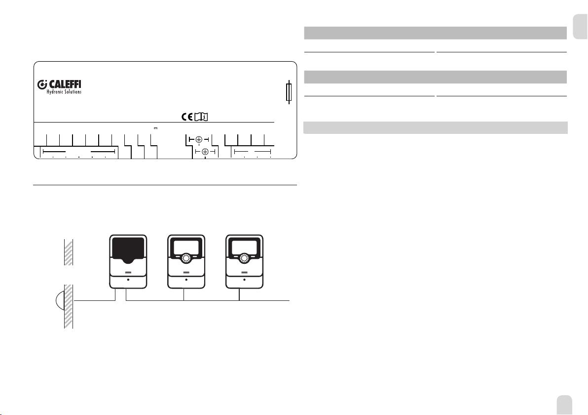
The device is equipped with 2 relays in total, to which loads can be connected:
Semiconductor relay R1:
Conductor R1
Neutral conductor N (common terminal block)
Protective earth conductor ⏚(common terminal block)
Relay 2 is a potential-free extra-low voltage relay, e. g. for connection to a building
management system
Connect the temperature sensor to the terminals S1 and GND with either polarity.
The device is supplied with power via a mains cable.The power supply of the device
must be 100 … 240 V~ (50 … 60 Hz).

5
en
Connect the mains cable to the following terminals:
Neutral conductor N
Conductor L
Protective earth conductor ⏚
VBus
VBus
R2
R2
GND
Sensors
S1
100 ... 240V
T2A
50-60 Hz
N
R1
R2|1 (1) A 30V
L
R1|1 (1) A 240 V~
Sensore temperatura
esterna centralizzato
IP 20
Manufactured
by RESOL - TYPE SLT
Heiskampstr. 10
D-45527 Hattingen
161020
1.3 Data communication / Bus
The device is equipped with the VBus®for data communication.The connection is
to be carried out at the terminals marked VBus with correct polarity.
161010 161010
161020
S1
VBus®VBus®
. . .
FAP13 outdoor
temperature sensor
20 controllers are connectable. For applications with more than 20 controllers,
please contact Calef S.p.A.
Relay allocation
R1
no alarm open (normally open)
alarm closed
R2
no alarm closed (normally closed)
alarm open
2 Function
The Central Outdoor Sensor detects the outdoor temperature and transmits this
value via the VBus®to the controllers connected.
If there is a sensor fault, the LED will ash, R1 will be energised and R2 switched off
(the potential-free contact will open).
LED ashing codes:
Permanent green: normal operation
Red ashing: sensor fault
Off: no power supply

6
en
WARNING! Electric shock!
Upon opening the housing, live parts are exposed!
ÎAlways disconnect the device from power supply be-
fore opening the housing!
The device is protected by a fuse.The fuse holder (which also holds the spare fuse)
becomes accessible when the cover is removed.To replace the fuse, pull the fuse
holder from the base.
Operating control LED ashes red.
Sensor fault.
°C Ω
Pt1000
°C Ω
Pt1000
-10 961 55 1213
-5 980 60 1232
0 1000 65 1252
5 1019 70 1271
10 1039 75 1290
15 1058 80 1309
20 1078 85 1328
25 1097 90 1347
30 1117 95 1366
35 1136 100 1385
40 1155 105 1404
45 1175 110 1423
50 1194 115 1442
Short circuit or line break.
Disconnected temperature sensors can be checked
with an ohmmeter. Please check if the resistance values
correspond with the table.
3 Troubleshooting
Fuse

7
en

Distributed by: Distributed by
Calef S.p.A.
S.R. 229, no 25,
IT-28010 Fontaneto
d’Agogna (NO)
© All contents of this document are protected by copyright.
Table of contents
Popular Accessories manuals by other brands

HoMedics
HoMedics MyBaby Slumber Scents MYB-A310WT manual

Mechatron
Mechatron KG5000 operating manual

wtw
wtw TetraCon 925 operating manual

Sentera Controls
Sentera Controls FCMF R Series Mounting and operating instructions

OBH Nordica
OBH Nordica sharpX-treme 9967 Instructions of use

Banner
Banner iVu Plus user guide