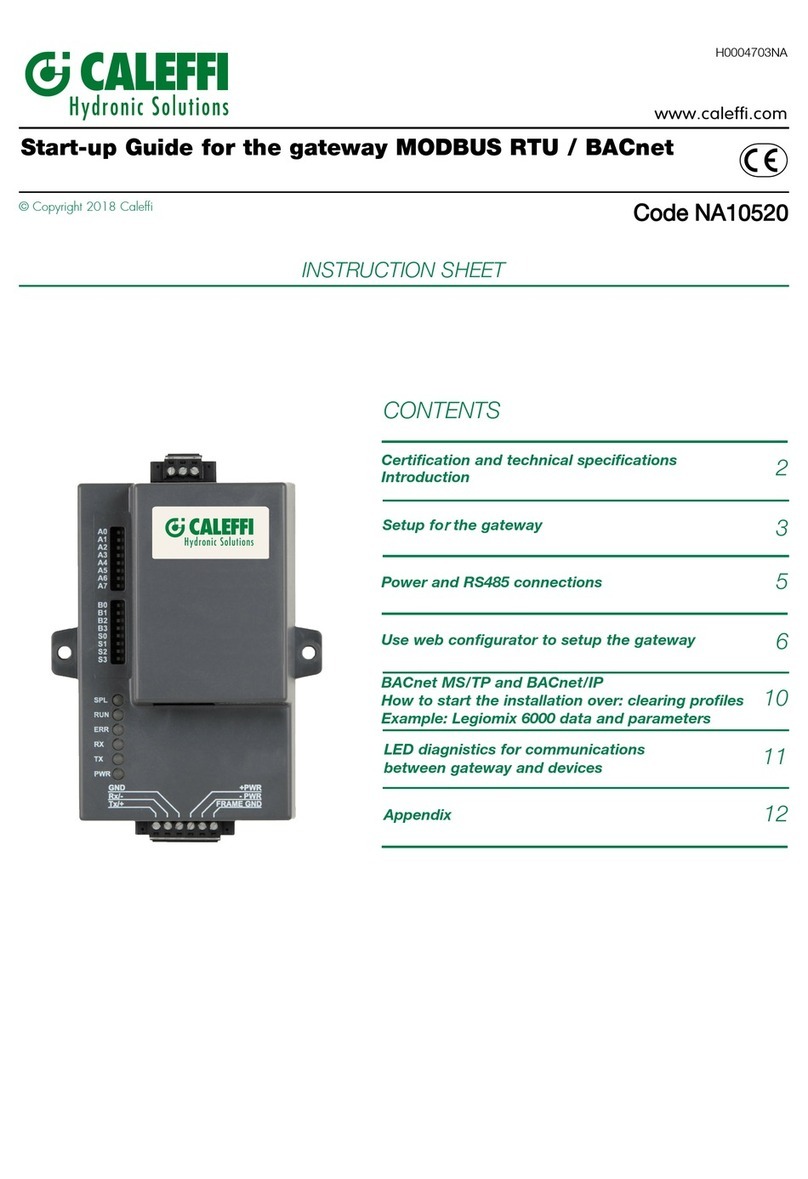
CALEFFI 755052 Series User guide

Start-up Guide for the gateway MODBUS RTU / BACnet
Serie 755052
CONTENTS
Certification and technical specifications
Introduction
Setup for the gateway
LED diagnostics for communications
between gateway and devices
2
3
6
11
10
INSTRUCTION SHEET
© Copyright 2019 Caleffi
H0004703.01
www.caleffi.com
2
Power and RS485 connections 5
Use web configurator to setup the gateway
BACnet MS/TP and BACnet/IP
How to clear profiles
Example: Legiomix 6000 data and parameters
Appendix 12

2
1. CERTIFICATIONS AND TECHINCAL SPECIFICATIONS
The BTL Mark on gateway is a symbol that indicates that a product has passed a series of rigorous tests conducted by
an independent laboratory which veries that the product correctly implements the BACnet features claimed in the listing.
The mark is a symbol of a high-quality BACnet product. Go to www.BACnetInternational.net for more information about the BACnet Testing Laboratory.
2. INTRODUCTION
The gateway is an external, high performance Building Automation multi-protocol gateway that is precongured to auto-discover any of Calef’s
products (hereafter called “device”) connected to the the gateway and automatically congures them for BACnet MS/TP, BACnet/IP. It is not necessary
to download any conguration les to support the required applications.
The gateway is pre-loaded with tested Proles/Congurations for the supported devices.
Device ADevice B Device C
One or multiple
Ethernet Field Protocol
BACnet IP
One or multiple Serial Devices
RS485 Modbus-RTU
Device D
One or multiple
RS485 BACnet MS/TP
Gateway FPC-N34
Electrical Connections
One 6-pin Phoenix connector with: RS-485 port (+ / - / gnd)
Power port (+ / - / Frame-gnd)
One 3-pin Phoenix connector with: RS-485 port (+ / - / gnd)
One Ethernet 10/100 BaseT port
Approvals
CE Certied; TUV approved to UL 916, EN 60950-1,
EN 50491-3 and CSA C22-2 standards; FCC Class A Part 15; DNP 3.0 Conformance Tested;
RoHS Compliant; CSA 205 Approved
BTL Marked
Power Requirements Multi-mode power adapter: 9-30V DC or 12 - 24V AC 2,5 W
Physical Dimensions 11.5 cm L x 8.3 cm W x 4.1 cm H (4.5 x 3.2 x 1.6 in.)
Weight 0.2 kg (0.4 lbs)
Operating Temperature -40°C to 75°C (-40°F to167°F)
Surge Suppression EN61000-4-2 ESD EN61000-4-3 EMC EN61000-4-4 EFT
Humidity 5 - 90% RH (non-condensing)
(Specications subject to change without notice)

3
3. SETUP FOR THE GATEWAY
Record identication data
Each gateway has a unique part number located on the side or the back of the unit. This number should be recorded, as it may be required for technical
support. The numbers are as follows:
Model Calef code
FPC-N34-1618 755052
The gateway have the following 3 ports: RS-485 + Ethernet + RS-485
Point count capacity and registers per device
The total number of registers presented by all of the devices attached to the gateway cannot exceed:
Model Calef code Total Registers
FPC-N34-1618 755052 1,500
Devices Registers Per Device
Legiomix_6000_Series 43
Legiomix_2_0_6000_Series 54
Conteca_Easy_750_Series 40
Conguring device communications
Input COM Settings on all Devices Connected to the gateway:
- All the connected serial devices must have the same Baud Rate, Data Bits, Stop Bits, and Parity settings as the gateway.
- The table species the device serial port settings required to communicate with the gateway.
Port Setting Legiomix_6000_Series Legiomix_2_0_6000_Series Conteca_Easy_750_Series
Protocol Modbus RTU Modbus RTU Modbus RTU
Baud Rate 9600 9600 9600
Parity None Even* / None Even* / None
Data Bits 8 8 8
Stop Bits 1 1 1
Set Modbus Node-ID for each device attached to the gateway
- Set Modbus Node-ID for each of the devices attached to gateway. The Node-ID’s need to be uniquely assigned between 1 and 255.
- The Node-ID that is assigned for each device needs to be documented.
- The Node-ID’s assigned are used for deriving the device instance for BACnet/IP and BACnet MS/TP.
Selecting the desired eld Protocol
Gateway units use the “S” bank of DIP switches (S0 – S3) to select the eld protocol.
- See the table below for the switch settings to select.
- The OFF position is when the DIP switches are set closest to the outside of the box.
*Factory default setting = Even
*Factory default setting = BACnet/IP
Gateway FPC-N34 S Bank DIP Switches
Prole S0 S1 S2 S3
BACnet/IP* Off Off Off Off
BACnet MS/TP (single node) On Off Off Off
S0 – S3 DIP
Switches S Bank DIP Switch Location
Prole Settings for gateway
NOTE: When setting DIP switches, ensure that power to the board is OFF.

4
3
BMS Network settings: MAC address, device instance and Baud rate
BACnet MS/TP: Setting the MAC Address for BMS Network
- Only 1 MAC Address is set for gateway regardless of how many devices are connected to gateway.
- Set the BACnet MS/TP MAC Address of the gateway to a value between 1 to 127 (Master MAC Address); this is so that the BMS front end can
nd gateway via BACnet Auto-Discovery.
NOTE: Never set a BACnet MS/TP MAC Address of the gateway to a value from 128 to 255. Addresses from 128 to 255 are Slave Addresses and
can not be discovered by BMS front ends that support Auto-Discovery of BACnet MS/TP devices.
- Set “A” bank DIP switches A0 – A7 to assign a MAC Address to the gateway for BACnet MS/TP.
- Refer to Appendix 1 for the complete range of MAC Addresses and DIP switch settings.
NOTE: When setting DIP switches, ensure that power to the board is OFF.
BACnet: Calculating the default device instance
The device instance value is automatically generated using the following formula:
BACnet device instance = (Device Node ID) + (Default Node Offset)
NOTE: The default node offset is 50,000.
For example, if device A has a node ID of 1 and device B has a node ID of 2, then:
BACnet device instance A = (1) + (50000) = 50001
BACnet device instance B = (2) + (50000) = 50002
To reach a specic BACnet device instance result, refer to the chapter 6.
BACnet MS/TP: Setting the Baud rate for BMS network
DIP switches B0 – B3 can be used to set the eld Baud rate of the gateway to match the Baud rate required by the BMS for BACnet MS/TP.
NOTE: When setting DIP switches, ensure that power to the board is OFF
Baud Rate DIP Switch Selection
Baud B0 B1 B2 B3
9600 On On On Off
19200 Off Off Off On
38400* On On Off On
57600 Off Off On On
76800 On Off On On
* Factory default setting = 38400
S3 DIP Switch Auto-Discovery Mode S3
Auto-Discovery ON - Build New Conguration On
Auto-Discovery OFF - Save current Conguration Off
Enabling Auto-Discovery
The S3 DIP switch is used to both enable Auto-Discovery of known devices attached to the gateway and save the recently discovered conguration.
If the gateway is being installed for the rst time, set the S3 to the ON position to enable Auto-Discovery. The ON position is when the DIP switches
are set clotest to the inside of the box.

Power-Up gateway
BACnet MS/TP: Wiring eld port to RS-485 Network
Connect the BACnet MS/TP RS-485 network wires to the 3-pins RS-485 connector on gateway
as shown below (use standard grounding principles for RS-485 GND):
Pins Device Pins Gateway Pins
1 Pin RS-485 + +
2 Pin RS-485 - -
3 Pin GND SG
4 Power In (+) PWR +
5 Power In (-) PWR -
6 Frame Ground FG
Pins Device Pins Gateway Pins
1 Pin RS-485 + +
2 Pin RS-485 - -
3 Pin RS-485 GND G
Check power requirements in the table below:
See the section 5 for information on connection to BACnet/IP network.
Power Requirement for gateway External
Current Draw Type
Gateway Family 12V DC/AC 24V DC/AC 30V DC
FPC – N34 (Typical) 170mA 100mA 80mA
FPC – N34 (Maximum) 240mA 140mA 100mA
NOTE: These values are ‘nominal’ and a safety margin should be added to the
power supply of the host system. A safety margin of 25% is recommended.
Apply power to gateway as shown below. Ensure that the power supply used complies with the specications provided in chapter 1.
- Gateway accepts either 9-30V DC or 12-24V AC on pins 4 and 5.
- Frame GND should be connected.
5
Auto-Discovery: After completion - Turn Off to save conguration
The S3 DIP Switch for enabling Auto-Discovery should have been set in the previous chapter before applying power to the gateway.
NOTE: Do not enable Auto-Discovery when the unit is powered.
When power is applied to a gateway that is set to enable Auto-Discovery, it will take about 3 minutes to complete the discovery of all the RS-485
attached to the gateway (the “TX” led will ash during the Auto-Discovery). Once completed, the “TX” and “RX” leds should ash rapidly, indicating
good communication between discovered devices.
Once the gateway has discovered all the RS485 devices, set the S3 DIP switch to the OFF position to save the current conguration.
S3 DIP Switch Auto-Discovery Mode S3
Auto-Discovery ON - Build New Conguration On
Auto-Discovery OFF - Save current Conguration Off
4. POWER AND RS485 CONNECTIONS
Device connections to gateway
Gateway 6 Pin Phoenix connector for RS-485 Devices:
- Pins 1 through 3 are for RS-485 devices (Use standard grounding principles for ModBus RTU RS-485 GND).
- Pins 4 through 6 are for power.
NOTE: Do not connect power until next chapter.

7
6
Wiring diagrams: from devices (MODBUS-RTU) to Gateway (Ethernet)
See the diagrams below for the connection for the different devices (from MODBUS to BACnet network).
Device - Gateway connections
Gateway Pins
Devices + -
Legiomix_2_0_6000_Series A B
Legiomix_6000_Series (18) (16)
Conteca_Easy_750_Series (17) (18)
5
5. USE WEB CONFIGURATOR TO SETUP THE GATEWAY
Connect the PC to gateway via the Ethernet Port
Connect a CAT5 Ethernet cable (Straight through or Cross-Over) between the local PC and gateway.
NOTE: The Default IP Address of gateway is 192.168.1.24, subnet mask is 255.255.255.0. If the PC and gateway are on different
IP Networks, assign a static IP Address to the PC on the 192.168.1.1 network.
Device ADevice B Device C
One or multiple
Ethernet Field Protocol
BACnet IP
One or multiple Serial Devices
RS485 Modbus-RTU
Device D
One or multiple
RS485 BACnet MS/TP
Device ADevice B Device C
One or multiple
Ethernet Field Protocol
BACnet IP
One or multiple Serial Devices
RS485 Modbus-RTU
Device D
One or multiple
RS485 BACnet MS/TP
GATEWAY
Legiomix 2.0 6000 Series
RS-485 cable
Ethernet cable
Power
Legiomix 6000 Series
Conteca Easy 750 Series

7
To set up the gateway by different Windows version follow the instruction below:
1 - Go to the start button and digit the following code: ncpa.cpl
- For Windows 10 - For Windows 8
2 - Select “Properties” by the right button of the mouse. 3 - Select “Internet Protocol Version 4” and conrm.
4 - Fill the corret setting for the IP BACnet gateway address. Connecting to gateway Web Congurator
Change the IP address of the Gateway Modbus RTU / BACNET:
If for network conguration reasons, the IP address 192.168.1.24
is already assigned in the network, the IP address of the Gateway
Modbus RTU / BACNET can be changed.
1. Open a web browser on the PC and enter the IP Address of the
gateway; the default address is 192.168.1.24;
2. At the bottom-left of the page, click the “Network” button;
3. Set a new IP address for Gateway Modbus RTU / BACNET at the
voice “N1 IP Address”;
4. Click “Save”.
Now, open a web browser on the PC and enter the IP Address of the
gateway; insert the new address.

8
To set up the gateway for MAC systems follow the instruction below:
1 - Open “System Preferences” 2 - Go to “Network” and choose the Ethernet system connected,
ll the correct setting for the IP BACnet gateway address
Connecting to gateway Web Congurator
After setting a local PC on the same subnet as the gateway (previous chapter), open a web browser on the PC and enter the IP Address of the gateway;
the default address is 192.168.1.24.
After setting the local IP address of the gateway, to show the parameters of the connected device, following the screens below.
Select the command “Congure” (1) and the command “Proles Conguration” to enter on the “Conguration Parameters” menù.
2
1

9
The Active proles section lists the currently active device proles, including previous Web Congurator additions. This list is empty for new installations,
or after clearing all congurations. To add an active prole to support a device, click the Add button under the Active Proles heading. This will present
a drop-down box underneath.The Current prole column that lists all the available proles.
For every device that is added, assign a unique Modbus Node-ID. This specication must match the device’s network settings.
Once the Prole for the device has been selected from the drop-down list, enter the value of the device’s Modbus Node-ID which was assigned in set
modbus node - ID. Then press the “Submit” button to add the Prole to the list of devices to be congured.
Repeat this process until all the devices have been added. Completed additions are listed under “Active Proles” as shown in the following gure.
3
NOTE: Below the “Active proles”
heading, the proles for connected
devices are listed. If no proles are
present, then wiring, baud rate and
DIP switch settings must be
checked, because there is a problem
with device communications. All the
active proles must show the
correct Node-ID’s before proceeding.
NOTE: If multiple devices are
connected to the gateway, set the
Virtual Server Nodes eld to “YES”;
otherwise leave the eld on the
default “No” setting (3).

10
6. BACNET MS/TP AND BACNET/IP: SETTING NODE_OFFSET TO ASSIGN SPECIFIC DEVICE INSTANCES
After setting a local PC to the same subnet as the gateway, open a web browser on the PC and enter the IP Address of the gateway; the default
address is 192.168.1.24. If the IP Address of the gateway has been changed by previous conguration, the assigned IP Address must be gathered
from the network administrator (The Web Congurator is shown in the chapter 5).
Node_offset eld shows the current value (default = 50,000).
NOTE: The values allowed for a BACnet Device Instance can range from 1 to 4,194,303
To assign a specic device instance (or range); change the Node_offset value as needed using the calculation below:
Device instance (desired) = Node_offset + Modbus Node_ID
For example, if the desired Device Instance for the device 1 is 50,001 and the following is true:
- Device 1 has a Modbus Node-ID of 1
- Device 2 has a Modbus Node-ID of 2
- Device 3 has a Modbus Node-ID of 3
Then plug the device 1’s information into the formula to nd the desired Node_offset:
- 50,001 = Node_offset + 1
- 50,000 = Node_offset
Once the Node_offset value is input, it will be applied to all devices as shown below:
- Device 1 Instance = 50,000 + Modbus Node_ID = 50,000 + 1 = 50,001
- Device 2 Instance = 50,000 + Modbus Node_ID = 50,000 + 2 = 50,002
- Device 3 Instance = 50,000 + Modbus Node_ID = 50,000 + 3 = 50,003
Click “Submit” once the desired value is entered.
7. HOW TO CLEAR PROFILES
After setting a local PC to the same subnet as the gateway, open a web browser on the PC and enter the IP Address of the gateway; the default
address is 192.168.1.24.
If the IP Address of the gateway has been changed by previous conguration, the assigned IP Address must be gathered from the network administrator
(the Web Congurator is shown in the chapter 5).
At the bottom-left of the page, click the “Clear Proles and Restart” button. Once restart is complete, old proles discovered and/or added via Web
congurator are deleted. Now the unit can be reinstalled.
BACnet: Setting Network_Number for more than one gateway on Subnet
For both BACnet MS/TP and BACnet/IP, if more than on gateway is connected to the same subnet, they must be assigned unique Network_Number
values. On the main Web Congurator screen, update the BACnet Network Number eld and click submit. The default value is 50.
8. EXAMPLE: LEGIOMIX 6000 DATA AND PARAMETERS
To show the parameters of the connected devices, following the screens below.
Select “Device List” to show the devices proles (1)
Select the prole of the connected device (2).
1
2

11
The parameters of the select device are shown in the screen below.
9. LED DIAGNOSTICS FOR COMMUNICATIONS BETWEEN GATEWAY AND DEVICES
See the diagram below for gateway led locations.
Tag Description
SPL The SPL LED will light if the unit is not getting a response from one or more of the congured
devices
RUN The RUN LED will start ashing 20 seconds after power indicating normal operation.
ERR
The SYS ERR LED will go on solid 15 seconds after power up. It will turn off after 5 seconds.
A steady red light will indicate there is a system error on the unit. If this occurs, immediately
report the related “system error” .
RX The RX LED will ash when a message is received on the serial port on the 6-pin connector.
If the serial port is not used, this LED is non-operational.
TX The TX LED will ash when a message is sent on the serial port on the 6-pin connector.
If the serial port is not used, this LED is non-operational.
PWR This is the power light and should show steady green at all times when unit is powered.

12
11
Appendix 1. “A” BANK DIP SWITCH SETTINGS
Address A0 A1 A2 A3 A4 A5 A6 A7
1On Off Off Off Off Off Off Off
2Off On Off Off Off Off Off Off
3On On Off Off Off Off Off Off
4Off Off On Off Off Off Off Off
5On Off On Off Off Off Off Off
6Off On On Off Off Off Off Off
7On On On Off Off Off Off Off
8Off Off Off On Off Off Off Off
9On Off Off On Off Off Off Off
10 Off On Off On Off Off Off Off
11 On On Off On Off Off Off Off
12 Off Off On On Off Off Off Off
13 On Off On On Off Off Off Off
14 Off On On On Off Off Off Off
15 On On On On Off Off Off Off
16 Off Off Off Off On Off Off Off
17 On Off Off Off On Off Off Off
18 Off On Off Off On Off Off Off
19 On On Off Off On Off Off Off
20 Off Off On Off On Off Off Off
21 On Off On Off On Off Off Off
22 Off On On Off On Off Off Off
23 On On On Off On Off Off Off
24 Off Off Off On On Off Off Off
25 On Off Off On On Off Off Off
26 Off On Off On On Off Off Off
27 On On Off On On Off Off Off
28 Off Off On On On Off Off Off
29 On Off On On On Off Off Off
30 Off On On On On Off Off Off
31 On On On On On Off Off Off
32 Off Off Off Off Off On Off Off
33 On Off Off Off Off On Off Off
34 Off On Off Off Off On Off Off
35 On On Off Off Off On Off Off
36 Off Off On Off Off On Off Off
37 On Off On Off Off On Off Off
38 Off On On Off Off On Off Off
39 On On On Off Off On Off Off
40 Off Off Off On Off On Off Off
41 On Off Off On Off On Off Off
42 Off On Off On Off On Off Off
43 On On Off On Off On Off Off
44 Off Off On On Off On Off Off
45 On Off On On Off On Off Off
46 Off On On On Off On Off Off
47 On On On On Off On Off Off
48 Off Off Off Off On On Off Off
49 On Off Off Off On On Off Off
50 Off On Off Off On On Off Off
Address A0 A1 A2 A3 A4 A5 A6 A7
51 On On Off Off On On Off Off
52 Off Off On Off On On Off Off
53 On Off On Off On On Off Off
54 Off On On Off On On Off Off
55 On On On Off On On Off Off
56 Off Off Off On On On Off Off
57 On Off Off On On On Off Off
58 Off On Off On On On Off Off
59 On On Off On On On Off Off
60 Off Off On On On On Off Off
61 On Off On On On On Off Off
62 Off On On On On On Off Off
63 On On On On On On Off Off
64 Off Off Off Off Off Off On Off
65 On Off Off Off Off Off On Off
66 Off On Off Off Off Off On Off
67 On On Off Off Off Off On Off
68 Off Off On Off Off Off On Off
69 On Off On Off Off Off On Off
70 Off On On Off Off Off On Off
71 On On On Off Off Off On Off
72 Off Off Off On Off Off On Off
73 On Off Off On Off Off On Off
74 Off On Off On Off Off On Off
75 On On Off On Off Off On Off
76 Off Off On On Off Off On Off
77 On Off On On Off Off On Off
78 Off On On On Off Off On Off
79 On On On On Off Off On Off
80 Off Off Off Off On Off On Off
81 On Off Off Off On Off On Off
82 Off On Off Off On Off On Off
83 On On Off Off On Off On Off
84 Off Off On Off On Off On Off
85 On Off On Off On Off On Off
86 Off On On Off On Off On Off
87 On On On Off On Off On Off
88 Off Off Off On On Off On Off
89 On Off Off On On Off On Off
90 Off On Off On On Off On Off
91 On On Off On On Off On Off
92 Off Off On On On Off On Off
93 On Off On On On Off On Off
94 Off On On On On Off On Off
95 On On On On On Off On Off
96 Off Off Off Off Off On On Off
97 On Off Off Off Off On On Off
98 Off On Off Off Off On On Off
99 On On Off Off Off On On Off
100 Off Off On Off Off On On Off

13
Address A0 A1 A2 A3 A4 A5 A6 A7
101 On Off On Off Off On On Off
102 Off On On Off Off On On Off
103 On On On Off Off On On Off
104 Off Off Off On Off On On Off
105 On Off Off On Off On On Off
106 Off On Off On Off On On Off
107 On On Off On Off On On Off
108 Off Off On On Off On On Off
109 On Off On On Off On On Off
110 Off On On On Off On On Off
111 On On On On Off On On Off
112 Off Off Off Off On On On Off
113 On Off Off Off On On On Off
114 Off On Off Off On On On Off
115 On On Off Off On On On Off
116 Off Off On Off On On On Off
117 On Off On Off On On On Off
118 Off On On Off On On On Off
119 On On On Off On On On Off
120 Off Off Off On On On On Off
121 On Off Off On On On On Off
122 Off On Off On On On On Off
123 On On Off On On On On Off
124 Off Off On On On On On Off
125 On Off On On On On On Off
126 Off On On On On On On Off
127 On On On On On On On Off
128 Off Off Off Off Off Off Off On
129 On Off Off Off Off Off Off On
130 Off On Off Off Off Off Off On
131 On On Off Off Off Off Off On
132 Off Off On Off Off Off Off On
133 On Off On Off Off Off Off On
134 Off On On Off Off Off Off On
135 On On On Off Off Off Off On
136 Off Off Off On Off Off Off On
137 On Off Off On Off Off Off On
138 Off On Off On Off Off Off On
139 On On Off On Off Off Off On
140 Off Off On On Off Off Off On
141 On Off On On Off Off Off On
142 Off On On On Off Off Off On
143 On On On On Off Off Off On
144 Off Off Off Off On Off Off On
145 On Off Off Off On Off Off On
146 Off On Off Off On Off Off On
147 On On Off Off On Off Off On
148 Off Off On Off On Off Off On
149 On Off On Off On Off Off On
150 Off On On Off On Off Off On
Address A0 A1 A2 A3 A4 A5 A6 A7
151 On On On Off On Off Off On
152 Off Off Off On On Off Off On
153 On Off Off On On Off Off On
154 Off On Off On On Off Off On
155 On On Off On On Off Off On
156 Off Off On On On Off Off On
157 On Off On On On Off Off On
158 Off On On On On Off Off On
159 On On On On On Off Off On
160 Off Off Off Off Off On Off On
161 On Off Off Off Off On Off On
162 Off On Off Off Off On Off On
163 On On Off Off Off On Off On
164 Off Off On Off Off On Off On
165 On Off On Off Off On Off On
166 Off On On Off Off On Off On
167 On On On Off Off On Off On
168 Off Off Off On Off On Off On
169 On Off Off On Off On Off On
170 Off On Off On Off On Off On
171 On On Off On Off On Off On
172 Off Off On On Off On Off On
173 On Off On On Off On Off On
174 Off On On On Off On Off On
175 On On On On Off On Off On
176 Off Off Off Off On On Off On
177 On Off Off Off On On Off On
178 Off On Off Off On On Off On
179 On On Off Off On On Off On
180 Off Off On Off On On Off On
181 On Off On Off On On Off On
182 Off On On Off On On Off On
183 On On On Off On On Off On
184 Off Off Off On On On Off On
185 On Off Off On On On Off On
186 Off On Off On On On Off On
187 On On Off On On On Off On
188 Off Off On On On On Off On
189 On Off On On On On Off On
190 Off On On On On On Off On
191 On On On On On On Off On
192 Off Off Off Off Off Off On On
193 On Off Off Off Off Off On On
194 Off On Off Off Off Off On On
195 On On Off Off Off Off On On
196 Off Off On Off Off Off On On
197 On Off On Off Off Off On On
198 Off On On Off Off Off On On
199 On On On Off Off Off On On
200 Off Off Off On Off Off On On

14
Address A0 A1 A2 A3 A4 A5 A6 A7
201 On Off Off On Off Off On On
202 Off On Off On Off Off On On
203 On On Off On Off Off On On
204 Off Off On On Off Off On On
205 On Off On On Off Off On On
206 Off On On On Off Off On On
207 On On On On Off Off On On
208 Off Off Off Off On Off On On
209 On Off Off Off On Off On On
210 Off On Off Off On Off On On
211 On On Off Off On Off On On
212 Off Off On Off On Off On On
213 On Off On Off On Off On On
214 Off On On Off On Off On On
215 On On On Off On Off On On
216 Off Off Off On On Off On On
217 On Off Off On On Off On On
218 Off On Off On On Off On On
219 On On Off On On Off On On
220 Off Off On On On Off On On
221 On Off On On On Off On On
222 Off On On On On Off On On
223 On On On On On Off On On
224 Off Off Off Off Off On On On
225 On Off Off Off Off On On On
226 Off On Off Off Off On On On
227 On On Off Off Off On On On
228 Off Off On Off Off On On On
229 On Off On Off Off On On On
230 Off On On Off Off On On On
231 On On On Off Off On On On
232 Off Off Off On Off On On On
233 On Off Off On Off On On On
234 Off On Off On Off On On On
235 On On Off On Off On On On
236 Off Off On On Off On On On
237 On Off On On Off On On On
238 Off On On On Off On On On
239 On On On On Off On On On
240 Off Off Off Off On On On On
241 On Off Off Off On On On On
242 Off On Off Off On On On On
243 On On Off Off On On On On
244 Off Off On Off On On On On
245 On Off On Off On On On On
246 Off On On Off On On On On
247 On On On Off On On On On
248 Off Off Off On On On On On
249 On Off Off On On On On On
250 Off On Off On On On On On
Address A0 A1 A2 A3 A4 A5 A6 A7
251 On On Off On On On On On
252 Off Off On On On On On On
253 On Off On On On On On On
254 Off On On On On On On On
255 On On On On On On On On

1514
Appendix 2. COMPLIANCE WITH UL REGULATIONS
For UL compliance, the following instructions must be met when operating gateway.
The units shall be powered by listed LPS or Class 2 power supply suited to the expected operating temperature range. The interconnecting power
connector and power cable shall:
- Comply with local electrical code.
- Be suited to the expected operating temperature range.
- Meet the current and voltage rating for gateway.
Furthermore, the interconnecting power cable shall:
- Be of length not exceeding 3.05m (118.3”)
- Be constructed of materials rated VW-1, FT-1 or better.
- If the unit is to be installed in an operating environment with a temperature above 65°C (149°F), it should be installed in a Restricted Access Area
requiring a key or a special tool to gain access.
- This device must not be connected to a LAN segment with outdoor wiring.
Appendix 3. VIEWING DIAGNOSTIC INFORMATION
- Type the IP Address of the gateway into the web browser to connect to the gateway.
- Click on Diagnostics and Debugging Button, then click on view, and then on connections.
- If there are any errors showing on the Connection page, refer to Appendix A.4 for the relevant wiring and settings.
Appendix 4. CHECK WIRING AND SETTINGS
No COMS on Modbus RTU side. If the Tx/Rx LEDs are not ashing rapidly then there is a COM issue. To x this, check the following:
- Visual observations of LEDs on gateway
- Check baud rate, parity, data bits, stop bits
- Check device address
- Verify wiring
- Verify device is connected to the same subnet as the gateway
- Verify the Modbus device was discovered in Web Congurator (Chapter 5)
- Field COM problems:
- If Ethernet protocols are used, observe Ethernet leds on the gateway
- Check dipswitch settings (using correct baud rate and device instance)
- Verify IP Address setting
- Verify wiring
Appendix 5. SECURING GATEWAY WITH PASSWORDS
Access to the gateway can be restricted by enabling a password on the FS-GUI Passwords page – click Setup and then Passwords in the navigation
panel. There are 2 access levels dened by 2 account names:
- The Admin account has unrestricted access to the gateway.
- The User account can view any gateway information, but cannot make any changes or restart the gateway.
The password needs to be a minimum of eight characters and is case sensitive. If the password is lost, click cancel on the password authentication
popup window, and email the password recovery token to support to receive a temporary password from the support team.
Access the gateway to set a new password.

16
Appendix 6. LEGIOMIX_6000_SERIES MODBUS RTU MAPPINGS TO BACNET
Point Name BACnet Object Type BACnet Object ID Description
Product type AV 16001
Address AV 21...247
Tmix Deg_C (Mixing temp.) AV 3°C
Trec Deg_C (Recirculation temp.) AV 4°C
Tmix Deg_F (Mixing temp.) AV 5°F
Trec Deg_F (Recirculation temp.) AV 6°F
State AV 71 - Regulation
2 - Disinfection
3 - Flushing
4 - Thermal shock
5 - Alarm
Program ID AV 80 - 0
1 - 1a
2 - 1b
3 - 2
Current Day AV 91...31
Current Month AV 10 1...12
Current Year AV 11 2017...
Current Hour AV 12 0...23
Current Minute AV 13 0...59
Language AV 14 0 - IT
1 - EN
2 - FR
3 - DE
4 - ES
5 - PT
6 - NL
7 - SL
8 - HR
9 - SR
10 - RO
Time ON (h) (Start dis.) AV 15 0...23 (h)
Time ON (m) (Start dis.) AV 16 0...59 (min)
Time OFF (h) (Stop dis.) AV 17 0...23 (h)
Time OFF (m) (Stop dis.) AV 18 0...59 (min)
Time Wait (before reading rec.) AV 19 1...255 (min)
Time min (to have correct dis.) AV 20 0...254 (min)
Time Flux (Time of closing relay 4
after ending the dis.)
AV 21 0...2550 (sec)
Time Shock (Time of duration) AV 22 1...4320 (min)
Set Reg Deg_C (Set Mix temp) AV 23 20...85 (°C)
Set Dis Deg_C (Set Dis temp) AV 24 40...85 (°C)
Set Ric Deg_C (Set Rec temp) AV 25 40...85 (°C)
Set Shock Deg_C (Set Shock temp) AV 26 30...85 (°C)
Set Tmax Deg_C (Set max temp) AV 27 50...90 (°C)
Set Reg Deg_F (Set Mix temp) AV 28 68...185 (°F)
Set Dis Deg_F (Set Dis temp) AV 29 104...185 (°F)
Set Ric Deg_F (Set Rec temp) AV 30 104...185 (°F)
Set Shock Deg_F (Set Shock temp) AV 31 86...185 (°F)
Set Tmax Deg_F (Set max temp) AV 32 122...194 (°F)
Daily Disinfection AV 33 bit 5: Saturday
bit 4: Friday
bit 3: Thursday
bit 2: Wednesday
bit 1: Tuesday
bit 0: Monday
bit 6: Sunday

17
Appendix 7. LEGIOMIX_2.0_6000_SERIES MODBUS RTU MAPPINGS TO BACNET
Point Name BACnet Object Type BACnet Object ID Description
Model AI 16002
ID Modbus AI 21...250
T1 AI 3°C (°F) *
T2 AI 4°C (°F) *
ID Number AI 51701...9952
Serial Number AI 60001...9999
Status AI 70 = Motor test
1 = Zero acquisition
2 = Full scale acquisition
3 = Water mixing status
4 = Thermal shock status
5 = Thermal disinfection status
Alarms AL01 BI 81 = AL01
Alarms AL03 BI 91 = AL03
Alarms AL04 BI 10 1 = AL04
Alarms AL05 BI 11 1 = AL05
Alarms AL06 BI 12 1 = AL06
Alarms AL07 BI 13 1 = AL07
Alarms AL08 BI 14 1 = AL08
Alarms AL09 BI 15 1 = AL09
Presence of Recirculation Probe BV 34 1 = Presence of Rec probe
Anticlog BV 35 1 = Anticlog
Legal Hour AV 36 bit 2:0 bit 3:1 = Disabled
bit 2:1 bit 3:0 = EUR
bit 2:0 bit 3:1 = USA
bit 2:1 bit 3:1 = Custom
International System of Unit BV 37 0 = °C , 1 = °F
LED Display Enable BV 38 1 = LED display enable
Shock Activation BV 39 1 = Shock Activation
Pin-code Reset BV 40 1 = Pin-code Reset
Disinfection Reset BV 41 2 = Disinfection Reset
Alarm Reset BV 42 3 = Alarm Reset
Historical Data BV 43 4 = Historical Data
Shock Deactivation BV 44 1 = Shock Deactivation
Time Motor (Time to move actuator
from close to open position)
AV 45 8...320 (sec)
Time Play (Delay of time in move-
ment of actuator while changing
direction)
AV 46 1...255 (sec)
Start Sunday Legal Hour *AV 47 -3, -2, -1, 1, 2, 3
Start Month Legal Hour AV 48 1...12
End Sunday Legal Hour *AV 49 -3, -2, -1, 1, 2, 3
End Month Legal Hour AV 50 1...12
*It’s possible to choose the day of the hour change by setting the parameter #36 (Legal Hour) to “Custom”:
set: -1 for the last Sunday of the month;
set: -2 for the second to last Sunday of the month;
set: -3 for the third last Sunday of the month;
set: 1for the rst Sunday of the month;
set: 2for the second Sunday of the month;
set: 3for the third Sunday of the month.

18 19
Alarms AL10 BI 16 1 = AL10
Alarms AL11 BI 17 1 = AL11
IN1 Status BI 18 1 = disabled ; 0 = enabled
IN2 Status BI 19 1 = disabled ; 0 = enabled
OUT1 Status BI 20 1 = enabled ; 0 = disabled
OUT2 Status BI 21 1 = enabled ; 0 = disabled
OUT3 Status BI 22 1 = enabled ; 0 = disabled
Adjustment Status AI 23 0 = Not in progress
1 = On max temperature limit
2 = T1 enabled control
3 = T2 enabled control with d2 type
4 = T2 enabled control with d1 type
5 = DT measurement in progress
Motor Status AI 24 0 = Motor stopped
1 = Motor opening
2 = Motor closing
Device Adjustment Status AI 25 0 = Without adjustment
1 = Adjustment on band 1
2 = Adjustment on band 2
3 = Adjustment on band 3
4 = Adjustment in position
DN AI 26 0 = DN15
1 = DN20
2 = DN25
3 = DN32
4 = DN40
5 = DN50
Seconds AI 27 0...59
Current Day AI 28 1...7
Firmware AI 29 Firmware
Software AI 30 Software
Checksum AI 31 Checksum
Encoder Position AI 32 Encoder Position
Day AV 33 1...31
Month AV 34 1...12
Year AV 35 0...99
Hour AV 36 0...23
Minute AV 37 0...59
Check Battery BV 38 1 = conrmed ; 0 = not conrmed
Day-hour BV 39 1 = conrmed ; 0 = not conrmed
Daylight Saving Time BV 40 1 = enabled ; 0 = not disabled
Time Format BV 41 1 = 12H ; 0 = 24H
Temperature Unit BV 42 1 = °F ; 0 = °C
U.S. daylight Saving Time BV 43 1 = enabled ; 0 = disabled
Disinfection Control BV 44 1 = on T2 ; 0 = on T1
Encoder Steps Acquisition BV 45 1 = encoder steps acquisition
Set Point Temperature AV 46 35...65°C (°F) *
Disinfection Type AV 47 bit 1-0: 00 = ln1; 01 = ln2; 10 = ln3
bit 2: –
bit 3: –
bit 4: propagation time: 1 = xed; 0 = calculated
bit 5: ECO function: 1 = enabled; 0 = disabled
bit 6: –
bit 7: control on temp: 1 = d1; 0 = d2
Minimum Disinfection Temperature AV 51 50...85°C (°F) *
Minimum Disinfection Time AV 52 1...600
Maximum Disinfection Time AV 53 3...900
Disinfection Start Day Monday BV 54 1 = enabled ; 0 = disabled
Disinfection Start Day Tuesday BV 55 1 = enabled ; 0 = disabled

19
Disinfection Start Day Wednesday BV 56 1 = enabled ; 0 = disabled
Disinfection Start Day Thursday BV 57 1 = enabled ; 0 = disabled
Disinfection Start Day Friday BV 58 1 = enabled ; 0 = disabled
Disinfection Start Day Saturday BV 59 1 = enabled ; 0 = disabled
Disinfection Start Day Sunday BV 60 1 = enabled ; 0 = disabled
Monday Disinfection Starting Minute AV 61 0...59
Monday Disinfection Starting Hour AV 62 0...23
Tuesday Disinfection Starting Minute AV 63 0...59
Tuesday Disinfection Starting Hour AV 64 0...23
Wednesday Disinfection Starting Minute AV 65 0...59
Wednesday Disinfection Starting Hour AV 66 0...23
Thursday Disinfection Starting Minute AV 67 0...59
Thursday Disinfection Starting Hour AV 68 0...23
Friday Disinfection Starting Minute AV 69 0...59
Friday Disinfection Starting Hour AV 70 0...23
Saturday Disinfection Starting Minute AV 71 0...59
Saturday Disinfection Starting Hour AV 72 0...23
Sunday Disinfection Starting Minute AV 73 0...59
Sunday Disinfection Starting Hour AV 74 0...23
Time Bands 1 Ric Start BV 75 1 = enabled ; 0 = disabled
Time Bands 2 Ric Start BV 76 1 = enabled ; 0 = disabled
Time Bands 3 Ric Start BV 77 1 = enabled ; 0 = disabled
Time Bands 4 Ric Start BV 78 1 = enabled ; 0 = disabled
Time Bands 5 Ric Start BV 79 1 = enabled ; 0 = disabled
Time Bands 6 Ric Start BV 80 1 = enabled ; 0 = disabled
Minimum Thermal Shock Temperature AV 81 65...85°C (°F) *
Minimum Thermal Shock Time AV 82 0...4320
Maximum Thermal Shock Time AV 83 0...4320
Maximum Temperature Limit AV 84 65...85°C (°F) *
Thermal Schock BV 85 1 = Start ; 0 = Stop
Disinfection AV 86 1 = Start ; 0 = Stop
Reset active allarms BV 87 0 = no allarm; 1 = allarm
Reset istorical allarms BV 88 0 = no allarm; 1 = allarm
* WARNING:
if the “Temperature Unit” value is xed in ° F (value = 1) the temperatures reported are already converted into ° F (not in ° C as per displayed)
Example of reading the Disinfection Type value:
1 - Value read in the Congurator Parameters: 130 decimals value
2 - Conversion the value in binarys value (composed to 8 bit):
binarys value 10000010
bit 7° 6° 5° 4° 3° 2° 1° 0°
bit 0 0
==> ln3
bit 1 1
bit 2 0value not used
bit 3 0value not used
bit 4 0==> calculated
bit 5 0==> disabled
bit 6 0value not used
bit 7 1==> d1
3 - Interpretation of the reading Byte:

20
Appendix 8. CONTECA_EASY_750_SERIES MODBUS RTU MAPPINGS TO BACNET
Point Name BACnet Object Type BACnet Object ID Description
Product AI 17500
ID AI 21...250
Heating Energy AI 3kWh
Cooling Energy AI 4kWh
Pulse Input 1 AI 5 m3(DHW)
Pulse Input 2 AI 6 m3(DCW)
Pulse Input 3 AI 7 m3/ kWh
Pulse Input 4 AI 8 m3/ kWh
Power AI 9kW
Flow Rate AI 10 m3 / h
Flow Temperature AI 11 °C
Return Temperature AI 12 °C
Delta Temperature AI 13 Flow - Return Temperature
Alarm/Status AI 14 bit 0 : T Flow error
bit 1 : T Return error
bit 2 : No ow rate
bit 3 : Valve internal leakage
bit 4 : -
bit 5 : -
bit 6 : Battery error
bit 7 : No credit
bit 8 : Measurement unit error C0
bit 9 : Measurement unit error C1
bit 10 : Measurement unit error C2
bit 11 : Measurement unit error C3
bit 12 : Measurement unit error C4
bit 13 : -
bit 14 : -
bit 15 : -
Product (Imperial Units) AI 15 7500
ID (Imperial Units) AI 16 1...250
Heating Energy (Imperial Units) AI 17 kBTU
Cooling Energy (Imperial Units) AI 18 kBTU
Pulse Input 1 (Imperial Units) AI 19 kgal (DHW)
Pulse Input 2 (Imperial Units) AI 20 kgal (DCW)
Pulse Input 3 (Imperial Units) AI 21 kgal / kBTU
Pulse Input 4 (Imperial Units) AI 22 kgal / kBTU
Power (Imperial Units) AI 23 kBTU / h
Flow Rate (Imperial Units) AI 24 GPM
Flow Temperature (Imperial Units) AI 25 °F
Return Temperature (Imperial Units) AI 26 °F
Delta Temperature (Imperial Units) AI 27 Flow - Return Temperature
Alarm/Status (Imperial Units) AI 28 bit 0 : T Flow error
bit 1 : T Return error
bit 2 : No ow rate
bit 3 : Valve internal leakage
bit 4 : -
bit 5 : -
bit 6 : Battery error
bit 7 : No credit
bit 8 : Measurement unit error C0
bit 9 : Measurement unit error C1
bit 10 : Measurement unit error C2
bit 11 : Measurement unit error C3
bit 12 : Measurement unit error C4
bit 13 : -
bit 14 : -
bit 15 : -
Manufactured By
Sierra Monitor Corporation
1991 Tarob Court, Milpitas, CA 95035, USA
www.sierramonitor.com
Table of contents
Other CALEFFI Gateway manuals
Popular Gateway manuals by other brands

purexx
purexx PX-iP operating manual

Grandstream Networks
Grandstream Networks GXW42XX series user manual

Yeastar Technology
Yeastar Technology NeoGate TA800 user manual

AddPac
AddPac AP-GS1001 Setup guide

ZyXEL Communications
ZyXEL Communications P-660HW-Tx v3 Series user guide

RTA
RTA 460MCBC-N700 Product user guide

Telco Systems
Telco Systems ACCESS 241-FXO user guide

THOMSON
THOMSON SPEEDTOUCH 536I - V6 datasheet

Cisco
Cisco Small Business SPA8800 Configuring

ZyXEL Communications
ZyXEL Communications MAX-200M1 Series user guide

Comcast
Comcast WIRELESS GATEWAY user guide

DEUTSCHMANN AUTOMATION
DEUTSCHMANN AUTOMATION UNIGATE CM-CANopen instruction manual