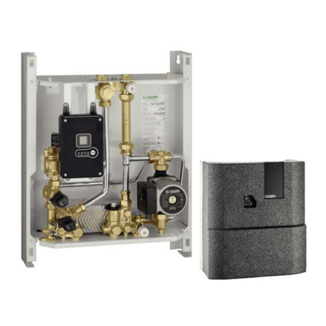
CALEFFI 528 Series User manual

G uppi di espansione pe scaldacqua ad accumulo
Expansion g oups fo hot wate sto age heate s
Siche heitsg uppe fü B auchwasse e wä me
I
GB
D
Funzione
Function
Funktion
I gruppi di espansione sono dispositivi utilizzati negli impianti idrosanitari per la
protezione degli scaldacqua ad accumulo.
The expansion groups are used in domestic water systems to protect hot water
storage heaters.
Sicherheitsgruppen sind Armaturen die in Trinkwasser erwärmungsanlagen zum Schutz
des Brauchwassererwärmer eingesetzt werden.
528046 DN 15 / 1/2” 6 bar
528048 DN 15 / 1/2” 8 bar
528041 DN 15 / 1/2” 10 bar
528056 DN 15 / 3/4” 6 bar
528058 DN 15 / 3/4” 8 bar
528051 DN 15 / 3/4” 10 bar
528156 DN 20 / 3/4” 6 bar
528158 DN 20 / 3/4” 8 bar
528151 DN 20 / 3/4” 10 bar
528166 DN 20 / 1” 6 bar
528168 DN 20 / 1” 8 bar
528161 DN 20 / 1” 10 bar
528
1
528
0
528 se ies
1
© Copyright 2013 Caleffi
Technical
specification
Product range
Materials:
- Body: brass EN 12165 CW617N
- Ball isolating valve: brass EN 12164 CW614N
- Check valve: dezincification resistant alloy CR EN 12165 CW602N + POM
- Expansion relief valve: brass EN 12165 CW617N
- Expansion relief valve obturator: EPDM
- Seals: EPDM
- Tundish: PP
Medium: water
Max. working temperature: 40°C
Max. working pressure: 10 bar
Expansion relief valve setting pressure: 6 - 8 - 10 bar
Connections: (5280) 1/2” - 3/4” (ISO 7/1) M; (5281) 3/4” - 1” (ISO 7/1) M
Discharge: pipe Ø 40 mm
Technical
specification
of insulation
Material: EPP
Thickness: 12 mm
Density: 45 kg/m3
Conductivity: at 10°C: 0 037 W/(m·K)
Temperature range: -5–120°C
Fire resistence (UL94): class HBF
48244
www.caleffi.com

Componenti -
Components - Komponenten
2
2 3
3
8
1A
4
9
1A. Rubinetto di intercettazione di monte
1B. Rubinetto di intercettazione di valle
2. alvola di ritegno
3. Tappo per il controllo dell’efficienza
della valvola di ritegno
4. alvola di espansione
. Imbuto di scarico a norma EN 1717
6. Manopola per scarico manuale
7. Tappo per eventuale sostituzione ritegno
8. Coibentazione
9. Presa di pressione
1A. Upstream shut-off cock
1B. Downstream shut-off cock
2. Check valve
3. Inspection port to check functionality of
the check valve
4. Expansion relief valve
. Discharge tundish
6. Knob for manual discharge
7. Plug for check valve replacement
8. Insulation
9. Pressure test port
1A. Absperrkugelhahn
1B. Absperrkugelhahn
2. Rückflussverhinderer
3. Prüföffnung zur Funktionskontrolle des
Rückflussverhinderers
4. Sicherheitsventil
. Ablauftrichter
6. Handrad für manuelle Entleerung
7. Stopfen für eventuellen Austausch des
Rückflussverhinderers
8. Isolierung
9. Druckmessstutzen
6
28
1A
1B
4
9 7
6

Application
diagrams
Certificazione
Approval
Zertifizierungen
I gruppi di espansione sono certificati come rispondenti ai requisiti richiesti dalla
norma europea EN 1488.
The expansion groups are certified as conforming to European Standard
EN 1488.
Die Sicherheitsgruppen sind den Anforderungen der Europäischen Richtlinie
EN 1488 gemäß zertifiziert.
Product
application
DCW
DHW
20 mm
Installazione
Installation
Einbau
1. È consigliabile effettuare una pulizia delle tubazioni prima della posa.
2. I gruppi di espansione come da schema sotto riportato devono essere installati
sopra il livello del bollitore per evitarne lo scarico completo in caso di manutenzione.
3. I gruppi di
espansione
devono essere installati collegando l’imbuto di scarico alla
tubazione di evacuazione.
4. Per limitare gli interventi della valvola di espansione dovuti all’aumento di volume
dell’acqua installa e un vaso d’espansione.
5. Nel caso di alta pressione dell’acqua in ingresso si consiglia di installare un
riduttore di pressione.
1. It is recommended that pipes are cleaned before installation (clean the boiler also if
the safety unit is replaced)
2. The
expansion groups
according to the following diagram should be installed
above the water heater level to avoid the full discharge in case of maintenance.
3. The
expansion groups
must be installed by connecting the discharge tundish to the
drainage piping.
4. In order to reduce the interventions of the expansion valve due to the increase of
water volume install an expansion vessel.
5. If the inlet water pressure is too high it is recommended that a pressure reducing
valve is fitted.
1. Vor der Installation der Sicherheitsgruppe sollten die Rohrleitungen gespült werden.
Beim Austausch der Sicherheitsgruppe ist außerdem der Brauchwassererwärmer zu reinigen.
2. Sicherheitsgruppen werden wie im Schema unten dargestellt über dem Boilerniveau
installiert um das vollständige Entleeren des Boilers während der Wartung zu vermeiden.
3. Für die Installation der Sicherheitsgruppen ist die Ausblasleitung an die
Abwasserleitung anzuschließen.
4. Zur Vermeidung von Verkrustungen und Undichtigkeiten der Sicherheitsgruppe
aufgrund eines hohen Wasservolumens sollte ein Ausdehnungsgefäß eingebaut werden.
5. Bei hohem Einlasswasserdruck ist der Einbau eines Druckminderers zu empfehlen.
3
Body DN 15 DN 20
Connections 1/2” 3/4” 3/4” 1”
Max. volume of domestic water storage 200 l 1000 l
Max. power of domestic water storage 75 kW 150 kW

Funzionamento
Operation
Arbeitsweise
a) In posizione di funzionamento il rubinetto di monte (1A) e il rubinetto di valle (1B)
(solo per gruppi 5281) dovrà essere aperto
. L'apertura del rubinetto permette
l'alimentazione del boiler. Il ritegno incorporato impedisce il ritorno dell'acqua calda.
b) La valvola di
espansione
del gruppo è tarata a 6 - 8 - 10 bar.
a) In the operating position the upstream cock (1A) and downstream cock (1B) must be
opened. Open the valve to supply the water heater. The built-in check valve prevents
hot water from flowing back.
b) The expansion relief valve in the unit is calibrated at 6 - 8 - 10 bar.
a) In Funktionsstellung sollte die Absperrung (1) gemäß der auf dem Hebel
aufgedruckten Anweisung geöffnet werden. Das Öffnen der Absperrung ermöglicht
das Einströmen des Wassers in den Boiler. Der eingebaute Rückflussverhinderer
verhindert den Rückfluss des Warmwassers in das System.
b) Das Sicherheitsventil der Gruppe ist auf 6 - 8 - 10 bar voreingestellt.
4
1. Per effettuare il controllo del corretto funzionamento del ritegno è necessario
dopo aver chiuso il rubinetto di monte (1A) svitare il tappo (3) situato dalla parte
opposta del rubinetto stesso. L’operazione va effettuata almeno una volta all’anno.
2. Nel gruppo serie 5281
in caso di necessità il ritegno può essere sostituito togliendo
il tappo (7) dopo aver chiuso entrambi i rubinetti. Durante la sostituzione assicurarsi
di aver inserito completamente il ritegno nella propria sede prima di riavvitare il tappo
di chiusura.
3. Per un buon funzionamento dei gruppi si consiglia di azionare manualmente
almeno una volta ogni 6 mesi la valvola di espansione e la valvola a sfera. Non
si devono assolutamente coprire
le prese d’aria antiriflusso.
4. La valvola di espansione può
essere sostituita assicurandone
la tenuta con appositi materiali
sigillanti.
1.
To control if the check valve works
correctly after closing the upstream
shut-off cock (1A) unscrew the
cap (3) which is situated on the
other side of the shut-off cock itself.
This operation should be performed
once a year at least.
2.
In 5281 series group if necessary
the check valve can be replaced
by removing the plug (7) after
shutting off both cocks. During the replacement be sure to fully insert the check valve
into its seat before screwing the closing plug.
3. For the expansion groups to work properly it is recommended to operate the
expansion relief valve and the ball valve by hand at least every 6 months.
The backflow preventer air gaps should never be covered.
4. The expansion valve can be replaced by ensuring the watertightness with
specific sealing materials.
1. Zur Funktionskontrolle des Rückflussverhinderers Absperrung (1A) schließen
und den gegenüberliegenden Stopfen (3) herausdrehen.
Gegebenenfalls kann der Rückflussverhinderer durch Entfernen des Stopfens (7)
ausgetauscht werden.
2. Bei Inbetriebnahme sowie mindestens einmal jährlich sind die Sicherheitsgruppe
und der Kugelhahn durch einen Fachmann zu überprüfen. Die Öffnungen des
Ablaufes dürfen auf keinen Fall verschlossen werden.
3. Für eine ordnungsgemäße Funktion der Sicherheitsgruppe ist es empfehlenswert
das Sicherheitsventil halbjährlich manuell zu betätigen.
4. Das Sicherheitsventil kann in Verbindung mit zugelassenen Dichtmitteln ersetzt
werden.
Controlli e
raccomandazioni
Controls and
recommendations
Wartung und
Kontrolle
3
1A
7

5
Verifica guasti
Failure check
Störungsbehebung
Guasto
La valvola di espansione
gocciola
Il ritegno non chiude
ermeticamente
La pressione dell’acqua è
scarsa o nulla
Causa
Espansione durante il
riscaldamento dell’acqua
Gocciola costantemente a
causa dello sporco
Aumento di pressione in
ingresso
Le superfici di tenuta sono
sporche o consumate
Rubinetti di intercettazione di
monte e/o di valle non
completamente aperti
Gruppo di espansione
non montato nella direzione
del flusso
Risoluzione
Nessun errore, funzionamento
normale
Azionare manualmente più
volte il comando manuale per
eliminare le particelle di
sporco o sostituire la valvola
di espansione se il problema
persiste
Sostituire il dispositivo
anti-riflusso (serie 5281)
Sostituire il dispositivo
anti-riflusso (serie 5281)
Aprire completamente i
rubinetti di intercettazione
Montare il gruppo di sicurezza
nella direzione del flusso
(indicata dalla
freccia)
Störung
Sicherheitsventil tropft
Der Rückflussverhinderer
schliesst nicht
Kein oder zu geringer
Wasserdruck
Ursache
Das Brauchwasser dehnt sich
in der Aufheitsphase aus
Auch nach der Aufheitsphase
tritt Wasser aus dem
Sicherheitsventil aus
Druckanstieg im
Kaltwassereingang
Schmutz, Ablagerungen auf
den Dichtflächen und
Dichtungen
Absperrungen nicht oder
nicht vollständig geöffnet
Sicherheitsgruppe nich in
Strömungsrichtung montiert
Lösung
Keine Störung
Sicherheitsventil per Hand
anlüften, um evtl.
Schmutzpartikel auszuspülen
Rückflussverhinderer ersetzen
(Serie 5281)
Rückflussverhinderer ersetzen
(Serie 5281)
Absperrungen vollständig
öffnen
Sicherheitsgruppe in
Strömungsrichtung montieren
(siehe Pfeil auf dem Gehäuse)
Failure
The expansion valve drops
The check valve does not
close watertightly
The water pressure is
insufficient or null
Cause
Expansion during water
heating
Continuous dropping due to
dirt
Increase in inlet pressure
The sealing surfaces are dirt
or worn
Upstream or downstream
shut-off cocks not fully open
Expansion group not installed
in the flow direction
Solution
No failure, normal functioning
Manually operate many times
the manual knob to eliminate
dirt particles or replace the
expansion valve if the problem
still remains
Replace the backflow
preventer device (5281 series)
Replace the backflow
preventer device (5281 series)
Fully open the shut-off cocks
Install the expansion group in
the flow direction (indicated
by the arrow)

6
Vista esplosa
Exploded view
Explosionszeichnung
Item Description Replace
1. Valvola di espansione 6 bar; 531460
Expansion relief valve 8 bar; 531480
Sicherheitsventil 10 bar; 531410
2. Imbuto di scarico –
Discharge tundish
Ablauftrichter
3. Raccordo per valvola di espansione –
Fitting for expansion relief valve
Verschraubung mit PTFE-Dichtung für Sicherheitsventil
4. Guarnizione di tenuta R60001
Seal
Dichtung
5. Tappo di controllo valvola di ritegno –
Plug for check valve inspection
Stopfen für Prüföffnung des Rückflussverhinderers
6. Bocchettoni 1/2”; R59482
Unions 3/4”; R59483
Verschraubungen 1”; R49359
7. Guarnizione di tenuta R60001
Seal
Dichtungen
8. Tappo presa di pressione –
Pressure test port plug
Stopfen für Prüföffnung
9. Ritegno R59742
Check valve
Rückflussverhinderer
10. Tappo alloggiamento ritegno –
Plug for check valve seat
Stopfen mit Sitz des Rückflussverhinderers

7
1
3
2
4
6 7 7 6
8
1
3
10
8
2
4
6 7 7 6
9
5280 series
528 series

8
ATTENZIONE! LA TUA SICUREZZA È COINVOLTA. UNA MANCANZA NEL SEGUIRE QUESTE
ISTRUZIONI PUÒ ORIGINARE PERICOLO
IL PRODOTTO CON IL QUALE E’ CONFEZIONATO QUESTO FOGLIO ISTRUZIONI E’ DENOMINATO
DISPOSITIVO
1 Il dispositivo deve essere installato, messo in servizio e manutenuto da personale tecnico qualificato
in accordo con i regolamenti nazionali e/o i relativi requisiti locali.
2 Se il dispositivo non è installato, messo in servizio e manutenuto correttamente secondo le istruzioni
contenute in questo manuale, allora può non funzionare correttamente e porre l’utente in pericolo.
3 Pulire le tubazioni da eventuali detriti, ruggini, incrostazioni, calcare, scorie di saldatura e da altri
contaminanti. Il circuito idraulico deve essere pulito.
4 Assicurarsi che tutta la raccorderia di collegamento sia a tenuta idraulica.
5 Nella realizzazione delle connessioni idrauliche, prestare attenzione a non sovrasollecitare
meccanicamente le filettature. Nel tempo si possono produrre rotture con perdite idrauliche a
danno di cose e/o persone.
6 emperature dell’acqua superiori a 50°C possono provocare gravi ustioni. Durante l’installazione,
messa in servizio e manutenzione del dispositivo, adottare gli accorgimenti necessari affinché tali
temperature non arrechino pericolo per le persone.
7 In caso di acqua molto dura o ricca di impurità, deve esserci predisposizione ad adeguata filtrazione
e
trattamento dell’acqua prima dell’ingresso nel dispositivo,
secondo la normativa vigente. In caso
contrario esso può venire danneggiato e non funzionare correttamente.
8 Per un funzionamento ottimale, l’aria contenuta nel fluido deve essere rimossa.
Per ragioni di sicurezza, a causa dell’alta comprimibilità dell’aria, sono sconsigliati i test di tenuta
sull’intero sistema, e in particolare sulle valvole, tramite aria compressa.
9 E’ vietato fare un utilizzo diverso del dispositivo rispetto alla sua destinazione d’uso.
10 Dispositivo non adatto per ambienti confinati ad uso agricolo.
11 L’eventuale abbinamento tra il dispositivo ed altri componenti dell’impianto deve essere effettuato
tenendo conto delle caratteristiche di funzionamento di entrambi. Un eventuale abbinamento non
corretto potrebbe pregiudicare il funzionamento del dispositivo e/o dell’impianto.
Lascia e il p esente manuale ad uso e se vizio dell’utente
CAUTION! YOUR SAFETY IS INVOLVED. FAILURE TO FOLLOW THESE INSTRUCTIONS MAY
RESULT IN DANGER.
THE PRODUCT SUPPLIED WITH THIS INSTRUCTION SHEET IS CALLED “DEVICE”
1 he device must be installed, commissioned and maintained by a licensed technician in
accordance with national regulations and/or relevant local requirements.
2 If the device is not installed, commissioned and maintained correctly in accordance with the
instructions provided in this manual, it may not work properly and may endanger the user.
3 Clean the pipes of all deposits, rust, incrustations, limescale, welding slag and any other
contaminants. he hydraulic circuit must be clean.
4 Make sure that all connection fittings are watertight.
5 When connecting water pipes, make sure that threaded connections are not mechanically
overstressed. Over time this may result in breakages, with consequent water leaks which could
harm people and/or damage property.
6 Water temperatures higher than 50°C may cause severe burns. When installing, commissioning
and maintaining the device, take the necessary precautions so that these temperatures will not
endanger people.
7 If the water is particularly hard or contains a lot of impurities, suitable filtration and treatment should
be performed to water before it enters the device, in accordance with current legislation. Otherwise
the device may be damaged and will not work properly.
8 For optimal operation, any air in the medium must be removed. For safety reasons, due to the high
compressibility of air, testing the entire system, and especially the valves, for watertightness using
compressed air is not recommended.
9 Any use of the device other than its intended use is prohibited.
10 he device is not suitable for use in agricultural applications.
11 Any coupling of the device with other system components must be made while taking the
operational characteristics of both units into consideration. An incorrect coupling could
compromise the operation of the device and/or system.
Leave this manual fo the use
Sicurezza
Safety
Sicherheit

ACHTUNG! ES GEHT UM IHRE SICHERHEIT. EINE MISSACHTUNG DIESER ANWEISUNGEN
KANN GEFAHRENSITUATIONEN VERURSACHEN
DAS PRODUKT, DEM DIESE BEDIENUNGSANLEITUNG BEILIEGT, WIRD ALS GERÄT BEZEICHNET
1 Die Gerät muss durch technisches Fachpersonal gemäß den nationalen und/oder lokalen
einschlägigen Vorschriften installiert, in Betrieb genommen und gewartet werden.
2 Die Mißachtung der Sicherheitsanweisungen kann zu Betriebsstörungen und Gefahr für den
Betreiber führen.
3 Die Rohrleitungen sind von Verunreinigungen wie Rost, Kalk, Lötrückständen u.s.w. zu
befreien. Das Rohrleitungssystem ist zu spülen.
4 Rohrverbindungen und Verschraubungen sind auf Dichtheit zu prüfen.
5 Es ist darauf zu achten die Rohrgewinde nicht zu überanspruchen um Leckagen und resultierende
Sach- und Personenschäden zu vermeiden.
6 Wassertemperaturen über 50°C können zu schweren Verbrühungen führen. Während Installation,
Inbetriebnahme und Wartung der Gerät sind die notwendigen Vorkehrungen zu treffen, damit diese
emperaturen keine Personen gefährden können.
7 Bei sehr hartem oder verunreinigtem Wasser muss das Wasser gemäß den einschlägigen
Vorschriften vor dem Eintritt in die Gerät gefiltert und aufbereitet werden. Andernfalls kann die Gerät
beschädigt werden und nicht korrekt funktionieren.
8 Luft im Fördermedium kann zu Betriebsstörungen führen und ist zu entfernen. Auf Druckprüfungen
mit kompressibler Luft sollte verzichtet werden.
9 Die Vorrichtung ist nur seinen Bestimmungen entsprechend einzusetzen.
10 Die Gerät ist für den Einsatz im landwirtschaftlichen Bereich nicht geeignet.
11 Bei einer eventuellen Kombination der Gerät mit anderen Anlagenkomponenten müssen die
Betriebsmerkmale beider Geräten berücksichtigt werden. Eine falsche Kombination könnte die
Funktionstüchtigkeit der Gerät und/oder der Anlage beeinträchtigen.
Installations- und Siche heitshinweise sind dem Benutze zu Ve fügung zu stellen
Other manuals for 528 Series
1
This manual suits for next models
12
Other CALEFFI Heater manuals
Popular Heater manuals by other brands

TREVIDEA
TREVIDEA G3 FERRARI TEPOR user manual

Thinicon
Thinicon EHB Series user manual

Williams
Williams 696542 OWNER'S OPERATION AND INSTALLATION MANUAL

UNIPRODO
UNIPRODO UNI SAUNA G4.5KW user manual

Olimpia splendid
Olimpia splendid CALDO UP Instructions for installation, use and maintenance

dalap
dalap HW 6206 instruction manual