call4tel NXGW-XET1 User manual

call4tel
NXGW-XET1
User Manual
INDEX
Introduction 4
Sample Application 4
The Front Panel 5
Main Features 6
Logging In 6
System Status 7
Description of System Status 7
Call Status 8
Time Settings 8
Example Time Settings 9
Login Settings 9
Description of Web Login Settings 10
Login Settings 10
General 11
Language Settings 11
Scheduled Reboot 11
Tools 11
Reboot Tools 11
Description of reboots 12
Update Firmware 12
Upload and Backup Configuration 12
Restore Configuration 12
System Information 13
T1/E1 13
General Settings 13
Advanced interface type 14
Port Details 14
PRI 15

2
Definition of Signaling 15
MFC/R2 17
Modify R2 variant 18
General 18
Description of General 19
Timer 20
Description of Timer 20
Group A 21
Group B 22
Group C 22
Group 1 22
Group 2 23
Chan-SS7 23
Link Set Settings 23
Chan-SS7 Link Set Settings 24
Definition of SS7 Link Set Settings 25
Link Settings 26
SS7 Edit Link Settings 26
SS7 Configuration file backup and restore 26
VOIP 27
SIP Endpoints 27
Main Endpoint Settings 27
None Registration 27
Endpoint Register with Gateway 28
This Gateway Register with the Endpoint 28
Definition of SIP Options 29
Advanced Registration Options 29
Call Settings 30
Advanced Signaling Settings 30
Advanced Timer Settings 31
Fax Options 32
IAX2 Endpoint 32
Edit IAX Endpoint “9001” 33
Definition of IAX2 Endpoint 33
Advanced SIP Settings 35
Advanced NAT Settings 35
Advanced RTP Settings 36
Parsing and Compatibility 37
Security 38
Media 39
Codec Settings 39
Advanced IAX2 Settings 39
Instruction of Music on Hold 40
Instruction of Codec Settings 41
Instruction of Jitter Buffer 41
Instruction of Misc Settings 42
Instruction of Quality of Service 42
Advanced fax settings 42
Routing 43
Call Routing Rule 43
Example for routing rules number conversion 44
Example Setup of Routing Rule 44
Definition of Routing Options 45
Description of Advanced Routing Rule 45
Time Patterns that will use this Route 46
Forward Number 46
Failover Call Through Number 46
Groups 47
Establish Group 47
Network 47
Network Settings 47
Definition of WAN/LAN Settings 48
DNS Servers 48
DDNS Settings 48
Definition of DDNS Settings 49
Toolkit 49
Network Connectivity Checking 49
Static Route Settings 50

3
Advanced 50
Asterisk API 50
Definition of Asterisk API 51
Asterisk CLI 52
Definition of Asterisk CLI 52
Definition of Lock/unlock channels 52
Asterisk File Editor 53
Auto Provisioning 53
Preparation 54
Configuring gateway 54
Definition of Auto Provision 54
Definition of system notice 55
Auto Provision interface 55
Configuring ACS 55
Definition of ACS files 56
Provisioning example 57
SNMP 62
Parameters in SNMP setting 62
Activating SNMP 63
Verify SNMP 63
TR069 65
Network Capture 67
Definition of Network capture 67
Network capture interface 67
Signal Capture interface 68
Port Recording interface 68
Cloud 68
Connecting to the Cloud 68
Definition of Cloud Management 69
User 69
Add User 69
User List 69
User Permissions 70
Logs 70
Log Settings 70
System Logs Output 71
Definition of Logs 72
System log 73
Asterisk logs 74
Call Statistics 74
System Notice 75

4
INTRODUCTION
NXGW-XET1 Gateway is an open-source Asterisk-based VoIP Gateway. It is a converged media gateway prod-
uct. This kind of gateway connects traditional telephone systems to IP networks and integrates VoIP PBX with
the PSTN seamlessly. With a friendly GUI, users may easily set up their customized Gateway. Also, secondary
development can be completed through AMI (Asterisk Management Interface).
It is developed with a wide selection of codecs and signaling protocol, including G.711A, G.711U, G.729, G.722,
G.723 and GSM. It supports PRI/SS7/R2 protocol. The NXGW-XET1 Gateway has good processing ability and
stability. The NXGW-XET1 gateway is 100% compatible with Asterisk, Elastix, 3CX, FreeSWITCH SIP server and
VOS VoIP operating platform.
Sample Application
5
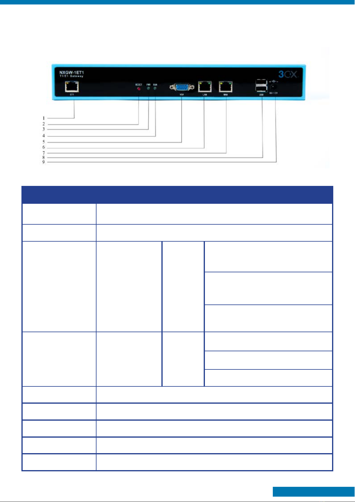
Front Panel
Interface Function Color Work Status
1 Port 1-Port4 ET1 ports. There is only one port.
2 Reset Reset button is used to restore the device.
3 RUN Register indicator Green
Slow blinking (Green 2s and Flash 0.1s):
Work normally.
Fast blinking (Green 0.5s and Flash
0.5s): Work abnormally.
Fast blinking (Green 0.5s and Flash
0.5s): Work abnormally.
4 PWR Power Status
indicator Green
No blinking: DAHDI Error.
On: Power is on.
Off: Power is off.
5 VGA VGA monitor connector.
6 LAN Network interface.
7 WAN Network interface.
8 USB USB interface.
9 DC-12V Power supply.

6
MAIN FEATURES
• Based on Asterisk®
• Editable Asterisk® configuration file
• Wide selection of codecs and signaling protocol
• Support 512 routing rules and flexible routing settings
• Stable performance, flexible dialing, friendly GUI
• Codecs support: G.711A, G.711U, G.729, G.723, G.722, GSM
• Support ports group management
• Support call status information
• Support T.38/Pass-through fax
• Support Auto Provision, SNMP and TR069
• Connect legacy PBX systems to low-cost VoIP services
• Connect legacy PBX systems to remote sites over private VoIP links
• Connect IP PBX systems to legacy TDM services
LOGGING IN
• Default IP: 172.16.100.1(WAN),
192.168.100.1(LAN)
• Username: admin
• Password: admin
• Notice: Log in

7
SYSTEM STATUS
Once logged in navigate to the “System Status” page. Here you will find all Interface status, channels status,
SIP, IAX2, Routing rules, and Network information.
DESCRIPTION OF SYSTEM STATUS
Options Definition
Interface Status Show the status of port, include “OK” and “Down”. “Down” means no trunk.
line connected; “OK” means the trunk line of port is available.
Channels Status
Show the Channels status of port, include “Idle“. “Busy“. “Disable” and “S
channel”. “Idle” means it is available;
“Busy” means the channel is busy.
“Disable” means it is unavailable;
“S channel” means signaling channel.

8
CALL STATUS
The verbose of the system call status will be present on the “Call Status” page. You can select the specified
T1/E1 port which you are care for.
TIME SETTINGS
Options Definition
System Time Your gateway system time.
Time Zone The world time zone. Please select the one which is the same or the
closest as your city.
POSIX TZ String Posix timezone strings.
NTP Server 1 Time server domain or hostname. For example, [0.cn.pool.ntp.org].

9
NTP Server 2 The first reserved NTP server. For example, [time.windows.com].
NTP Server 3 The second reserved NTP server. For example, [time.nist.gov].
Auto-Sync from NTP Whether enable automatically synchronize from NTP server or not. ON is
enable, OFF is disable this function.
Sync from NTP Sync time from NTP server.
Sync from Client Sync time from local machine.
Example Time Settings
You can set your gateway time Sync from NTP or Sync from Client by pressing different buttons.
LOGIN SETTINGS
Your gateway doesn’t have administration role. All you can do here is reset a new username and password to
manage your gateway. You can modify “Web Login Settings” and “SSH Login Settings”. If you have changed
these settings, you don’t need to logout, simply re-enter your new username and password. Also, you can
specify the web server port number. Usually, the web login default mode is “http and https”. For safety pur-
poses, you can switch to “only https” mode.

10
Description of Web Login Settings
Options Definition
User Name
Your gateway does not have administration role.
All you can do here is defining the user name and password to manage
your gateway.
And it has all privileges to operate your gateway .User Name: Allowed
characters “-_+<>&0-9a-zA-Z”.Length:1-32 characters.
Password Allowed characters “-_+. <>&0-9a-zA-Z”.
Length: 4-32 characters.
Confirm Password Please input the same password as ‘Password’ above.
Login Mode Specify the web login mode: http and https, only https. Default is http and
https.
Port Specify the web server port number. Do not use port 443 which is reserved
for HTTPS.
Login Settings
Notice: Whenever you make changes, do not forget to save your configuration.
Table of contents


