Calor De Hogar NTC-60 User manual

Calor de Hogar
Av Tecnológico 735, PB
San Salvador Tizatlalli
Metepec, 52172, Edo de México
Teléfono (722) 216 3330
(55) 1163 6038
www.calordehogar.com
servicio@calordehogar. omc

1
CONTENT
Content--------------------------------------------------------1
Introduction --------------------------------------------------2
Chapter 1 Parameters -----------------------------3
Chapter 2 Installation and Cautions -------------5
Chapter 3 Functions and Operation ------------12
Chapter 4 Maintenance --------------------------14
Chapter 5 Troubleshooting ----------------------15
Chapter 6 Warranty and Service ----------------16

2
INTRODUCTION
Thank you for choosing NTC series steam generator with well-designed structure,
steady performance and convenient installation. To form the whole set of steam
bathing equipment, you need a personal steam bathing room as well. The steam
generator is designed to remove tiredness, relax muscles and stimulate blood
circulation.
For proper installation, operation, maintenance, and the safety of customer
please read all instructions carefully and keep this manual for further reference.
ATTENION: This appliance is not intended for use by person with reduced
physical, sensory or mental capabilities, or lack of experience and
knowledge, unless they have been given supervision or
instruction concerning use of the appliance by a person
responsible for their safety.
ATTENION: Children should be supervised to ensure that they do not play
with the appliance.
ATTENTION:Check steam room before restart the controller.
ATTENTION: No smoking or alcohol is allowed inside the steam room
ATTENTION: Leave the steam room immediately when feels uncomfortable
ATTENTION: A ventilation fan is required outside the steam room.
CHAPTER 1 PARAMETERS

3
1. Models, parameters and dimension
Model
Power
(kW)
Heating
elements
(N*kW)
Voltage(V)/Current (A)
dimension
(length*Width*height)(in.)
NTC-45
4.5
3*1.5
240/18.6
163/4*65/16*123/8
NTC-60
6.0
3*2.0
240/25
NTC-90
9.0
6*1.5
240/37.5
183/4*71/4*173/4
NTC-120
12.0
6*2.0
240/50
Table 1
Figure 1
1. Frame 2. Service panel for water level sensor 3. Auto drain motor 4.Drainage valve
5.Connector 6.T-pipe
7. inlet magnetic valve 8. Side cover 9. Drainage pipe 10.Pipe cover 11. Base plate 12.
Heating element 13.Temp Switch
14. Water level sensor 15.Water tank 16.Underlay 17. Front panel 18. Connector 19.
T-pipe 20.Connector 21. Safety valve 22. Wire clamps 23. Wire terminal
24.Service cover 25.Mainboard 26.Sub-board

4
The Schematic diagram of the steam generator:
1
2
3
4
5
67
9
8
10
SIDE-BOARD
(RELAY)
AC240V
60Hz
FUSE
TERMINAL
11
12
1.Steam Outlet 2.Water Level Sensor 3.Temp Switch
4.Heating Elements 5.Inlet Valve 6.Drainage Outlet
7.Drainage Valve 8.Terminal 9.Side-Board(Relay)
10.Main PCB 11.Control Panel 12.Water Tank
13.Safety Valve
MAIN PCB
CONTROLLER
POWER SUPPLY
13
Figure 2
2. Controller parameters and dimension
Model
Controller
model
Controlling time
range
(minutes)
Temperature
display range
Temperature
controlling
range
dimension
(in.)
NTC series
NT-200
1~60
43℉~140℉
95~131℉
4.469*4.016*0.669
Table 2
Notice: the temperature sensor should be installed separately and connected to the controller with
wire. We recommend you to install the controller outside the steam room.

5
NT-200 controller
NT-200
Nature
Light button
Adjust button
Power button
Connector 2P
OFF
ON
TEMP TIME
OFF
PAUSE LIGHT
SET
ON
TIMETEMPTEMP TIME
Set temp indicator Temp display Set time indicator
Heating indicator Teat preserving
indicator
Pause button
Time,temp set button
Connector 6P
STEAM BATH CONTROL
Figure 3
CHAPTER 2 INSTALLATION AND CAUTIONS
Cautions:
If the generator is installed at a place where difficult for customer access, the water supply
valve must be easy to access for emergencies.
The maximum water pressure for electromagnetic valve is 2 bar. To protect the electromagnetic
valve from extremely high water pressure, please turn down the inlet slightly or install water
pressure relieving valve.
Do not install saddle-backed or needle valves on the inlet. Please dredge and clean the pipe
before installation.
No block valve should be installed in the steam pipelines. Strictly no blocked or blended pipe,
otherwise have negative affect on the flow of steam and condensate. The steam pipelines
should be installed with a slight angle so that the condensate can flow back to the generator or
the nozzle.
Steam generator should be installed indoor to avoid frozen. The generator should be installed
and leveled with the arrow pointing upward at an easy-access place, otherwise do not switch
on.
The steam pipeline must be copper pipes, all other material such as plastic, acrylic should not
be used since they cannot endure 302℉or higher. temperature
All inlet and apertures should be sealed to prevent any leakage of steam and to protect the
generator and customers.
Draining water directly to the steam room from the water tank may cause serious scald and
damage the steam room.
1. Selecting the proper steam generator:
In order to achieve comfort and relaxation, as well as energy efficiency, the selection of the
Heat Preserving

6
correct steam generator model and size are as critical as design of the steam room itself. The power
supply and circuit protector should be carefully checked to match the parameters of the generator.
Please referring to the table below and select the suitable model for your specification.
Power
kW
Room size
ft3
Voltage V/current A
Power line size
Fuse or breaker
A
4.0
124~194
240/18.6
3×12AWG
25
6.0
177~247
240/25
3×12AWG
40
9.0
283~388
240/37.5
3×10AWG
45
12.0
388~495
240/50
3×8AWG
60
Table 3
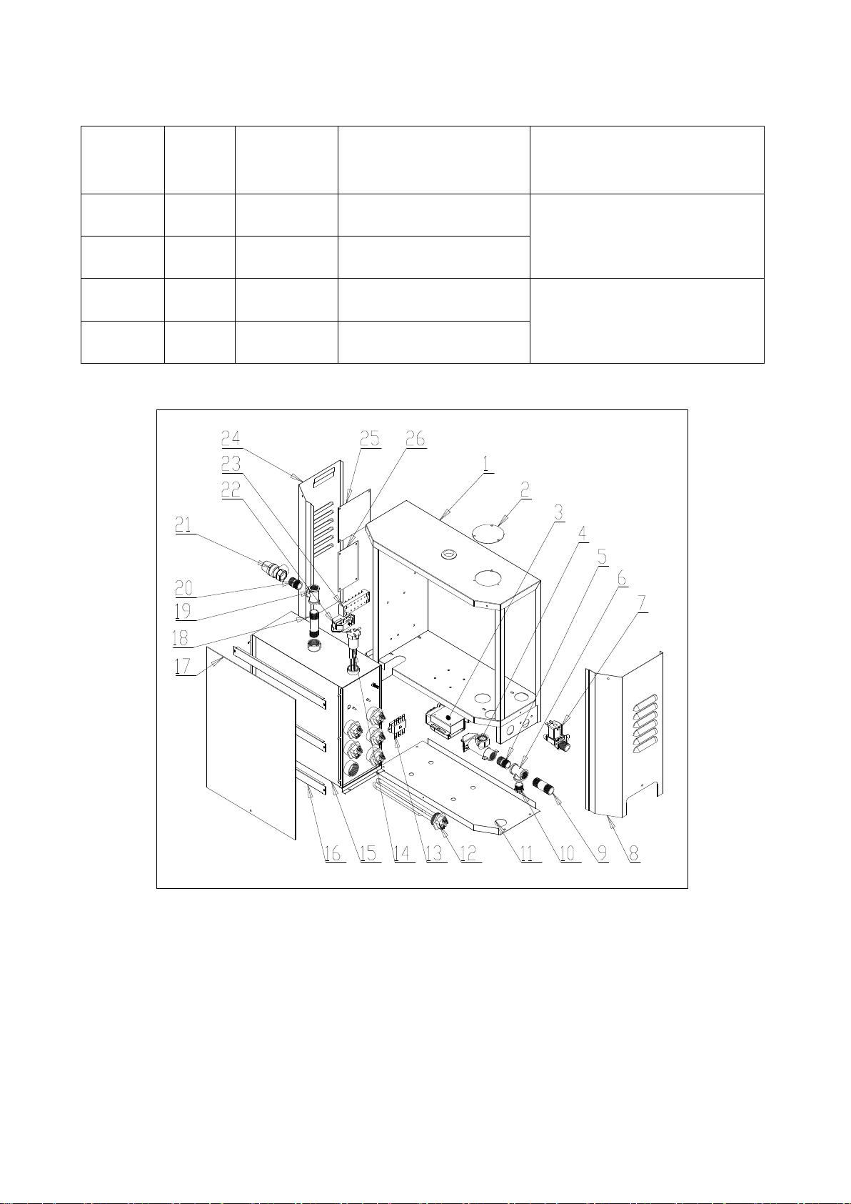
2. Installation of steam generator
Switch off all power supply before installation, and check whether you have the correct model
for your steam room according to table 3.
Do not install the generator outdoors, in wet/moist place, freezing, or corrosive place. Do not
install the generator near to inflammables such oil paint, diluents and fuel. Be alert to the steam
pipeline and safety valve since the high temperature of steam is dangerous to customers.
Generator must be level installed.
The generator should be installed in a dry and well-ventilated place. It can be installed either on
the wall or on the ground, but must be well-fixed. Install the generator as close to steam room as
possible, such as in the closet, under the washing basin or in the basement. (Refer to figure 4).
i. Install the generator on the wall: drill two small holes on the wall, insert the expansion
screws and then hang the generator on those screws.
ii. Install the generator on the ground or deck: Install the frame on the site and then screw the
generator into the frame.
iii. For better service and maintenance, please install the generator with the nameplate face to
front and leave more than 10"space around the generator.
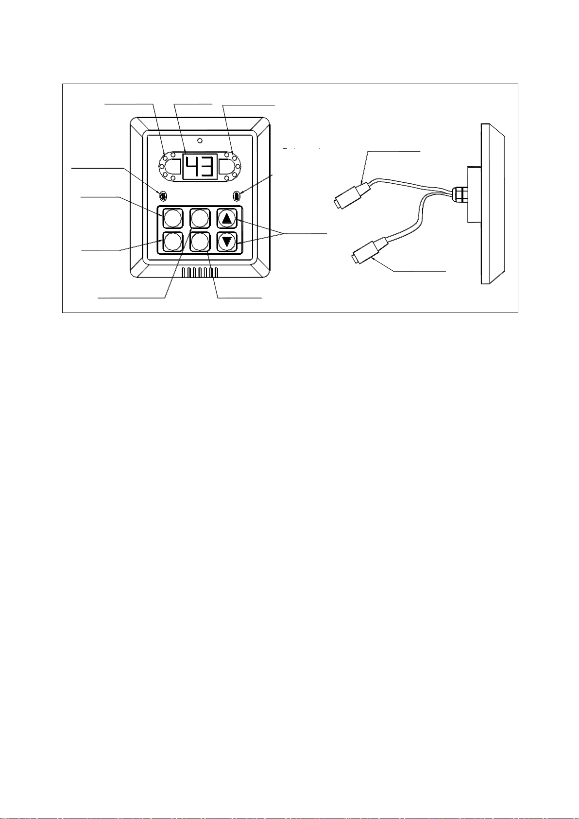
3. Installation of controller and temperature sensor
The controller should be installed with height of 47"outside the steam room but nearby or
other place where easy to operate. Firstly drill a hole with diameter 50mm (2 inch) on the
installation site, pull the control wire and temperature sensor wire through the conduit, then connect
the control wire to the black connector(6P) while connect the temperature sensor wire to the black
connector(2P). Finally the controller panel can be glued to wall by the double sided adhesive on the
back of the panel (Refer to figure 5).
The temperature sensor is used to measure the temperature inside the steam room, so that the
generator can work automatically according to the pre-set temperature and maintain the room
temperature constant. The installation height of the sensor should be about 47-59"from ground.
Please drill a ¢16mm (diameter 5/8‟‟ ) hole, and then nail down the sensor in the steam room
(Refer to figure6),, and pull the sensor wire through the conduit then connect to the black
connector(2P) of the controller.

7
Caution: The control wire and temperature wire should not be parallel to or intersect with the
power wire. The temperature sensor should not be installed on the side of the wall which is behind
the door when the door is opened and the controller should not be installed in any moist place.
Suitable
for installation
Install under
the washing basin
Install in the basement
Install in the closet
Install in the roof
DOUBLESIDED
ADHESIVE
TEMP SENSOR WIRE
CONTROL WIRE
CONTROLLER
WALL
CONDUIT
SENSOR WIRE
CONNECTOR 2P
CONTROL WIRE
CONNECTOR 6P
SEALING GLUE
Figure 4 Figure 5
TEMP SENSOR
IMMOBILIZING PLATE
IMMOBILIZING SCREW
WALL
SENSOR WIRE
Figure 6
4. Installation of pipeline
Caution:
If the generator is installed at a place where difficult for customer access, the water inlet valve
must be easy to access for emergencies.
The maximum water pressure for electromagnetic valve is 30psi. To protect the electromagnetic
valve from extremely high water pressure, please turn down the inlet slightly or install water
pressure relieving valve.
Do not install saddle-backed or needle valves on the inlet. Please dredge and clean the pipe
before installation.

8
No block valve should be installed in the steam pipelines. Strictly no blocked or blended pipe,
otherwise have negative affect on the flow of steam and condensate. The steam pipelines should
be installed with a slight angle so that the condensate can flow back to the generator or the
nozzle.
Steam generator should be installed indoors to prevent icing. The generator should be installed
and leveled with the arrow pointing upward at an easy-access place, otherwise do not switch on.
The steam pipeline must be copper pipes, all other material such as plastic, acrylic should not be
used since they cannot endure 302℉or higher temperature.
All inlet and apertures should be sealed to prevent any leakage of steam and protect the
generator and customers.
Draining water directly to the steam room from the water tank may cause serious scald and
damage the steam room. A separate draining pipe is required to drain water to the drainage.
All inlet water pipes and steam pipelines should be built according to the National Standard
(refer to Figure 7) and this should be done before sealing the wall.
Water inlet: First connect the water magnetizer (if applicable) to the water inlet solenoid valve.
Then please use a 1/2‟‟ flexible stainless steel hose to connect the other side of the water magnetizer
and the water supply pipeline. Do not connect to metal water supply pipeline directly which may
damage the water inlet valve. Only use cold water supply.
Steam outlet: Use no less than 1/2‟‟ copper pipe to connect the steam jet and the steam outlet pipe
of the generator. The pipe should be less than 10 ft long and minimize the number of elbows,
otherwise heat isolating methods should be implemented.
Steam nozzle: The steam nozzle should be about 1 ft from the ground and at least 6”from customer
seats. All nozzle should face downwards. Put the decorating cover onto the outlet pipe and firmly
seal with glue then screw on the nozzle. Do not screw too hard and break the cover and nozzle.

9
Figure 7
5. Electrical installation
Caution:
All electrical should be installed by licensed electricians and conform to local and national
codes.
Power supply must be cut off before installation, maintenance and repair. Press the on/off button
on the generator cannot cut power from the supply.
No additional power supply or wire is allowed to connect to the generator. Do not connect the
ground wire to the neutral wire.
Only the original parts and elements from our factory are allowed to be used in installation,
operation, maintenance and repair.
After the installation of the pipeline and electrical circuits, careful checking must be performed
before switch on the generator.
The generator has been carefully installed, checked and tested in factory, thus customer only
need to install the power wire and control wire.
INSTALLATION OF CONTROLWIRE
Take off the service cover of the generator, pull the control wire at the back of the controller
through a conduit and then insert it into the hole at the back of the generator case and connect to
the plug on the circuit board. (Refer to figure 8).
INSTALLATION OF POWER WIRE
Caution:
The power supply should be 240VAC,60Hz, please refer to the nameplate of the generator or
table1 of this manual.
Flexible
stainless
steel
hose

10
The selection of fuse and breaker must strictly follow the data in table 3.
Choose the suitable power wire according to table 3 and local codes.
Take off the service cover of the generator, insert the 3-core power wire (single phase, 240V,
60Hz ) into the hole at the back of the generator case and connect to the correct terminal. (Refer to
figure 9,10).
Single phase, 240V,60Hz power supply: connect one of the live wires to the terminal
labeled as “L1”; connect the other live wire to the terminal labeled as “L2”; and connect the
ground wire to the terminal labeled as “ ”.
240VAC60Hz
CONTROL
WIRE
CONTROLLER
N
GND
ZQJ0806
No100615
MAIN
BOARD
SUB-BOARD ZQJ-FB4.PCB
TERMINAL
K3K1
K4
CON1
K2
ZQJ-FB4.PCB
GND
V12
K2
K4
K6
K1
K5
K3
L1 L2
No 100615
GND
K3
K5
K1
K6
K4
K2
GND
LOW
Water level Probe
DRAIN HIGH
GND
ZQJ0806
DR
45min
POWER IN
L
NJUMP
K3
BT1
J2
D6
D5
P3
P1
P2
D4
D3
D2
D1
TEST
J1
SW1
ON
SW2
ON
IN VALVE
J5
D VALVE
J6
LAMP
J7
J3
K1
K4
J1-1

11
Figure 8
N
CIRCUIT DIAGRAM
NTC-45,NTC-60
240VAC60Hz GND
ZQJ0806 No100615
MAIN BOARD
INLET
VALVE
DRAINAGE
VALVE
LAMP
120V
SUB-BOARD
ZQJ-FB4.PCB
TERMINAL
TEMP SWITCH
HEATING ELEMENTS
CONTROLLER
WATER
LEVEL
SENSOR
K3K1
K4
CON1
K2
ZQJ-FB4.PCB
GND
V12
K2
K4
K6
K1
K5
K3
L1 240VAC60Hz L2
No 100615
GND
K3
K5
K1
K6
K4
K2
GND
LOW
Water level Probe
DRAIN HIGH
GND
ZQJ0806
DR
45min
POWER IN
L
NJUMP
K3
BT1
J2
D6
D5
P3
P1
P2
D4
D3
D2
D1
TEST
J1
SW1
ON
SW2
ON
IN VALVE
J5
D VALVE
J6
LAMP
J7
J3
K1
K4
J1-1
Figure 9

12
TEMP SWITCH
N
CIRCUIT DIAGRAM
NTC-90,NTC-120
240VAC60Hz
HEATING ELEMENTS
TERMINAL
GND L1 240VAC60Hz L2
SUB-BOARD
ZQJ-FB6.PCB
ZQJ-FB6.PCB
GND
V12
K2 K4
K1
K3 K5
K6
.
.
.
.
.
.
.
.
K3K2K1
K6
K5
CON1
K4
J1-1
K4 K1
J3
J7
LAMP
J6
D VALVE
J5
IN VALVE
ON
SW2
ON
SW1
J1
TEST
D1
D2
D3
D4
P2 P1 P3
D5
D6
J2
BT1
K3
JUMP
NL
POWER IN
45min
DR
ZQJ0806
GND
HIGH
DRAIN
Water level Probe
LOW
GND
K2
K4
K6
K1
K5
K3
GND
No 100615
WATER
LEVEL
SENSOR
LAMP
120V DRAINAGE
VALVE
MAIN BOARD
ZQJ0806 No100615
INLET
VALVE
CONTROLLER
Figure 10

13
CHAPTER 3 FUNCTIONS AND OPERATION
1. DISPLAY PANNEL
Temperature: The LCD will display the temperature measured by the temperature sensor in the
range of 43℉~140℉.
Set temperature: The temperature setting range is 95℉~131℉and indicated by the 5 red
LEDs besides the LCD. The bottom LED is on when temperature is 95℉; the bottom two LEDs are
on when the temperature is within range of 97℉~104℉; three LEDs are on when temperature is
within range of 106℉~113℉;four LEDs are on when temperature is within range of 115℉~
122℉; all LEDs are on when temperature is within range of 124℉~131℉. The default setting
temperature is 109℉.
Set time: The maximum setting time is 60 minutes and the remaining time is indicated by the 5
red LEDs besides the LCD. The bottom LED is on when the remaining working time is 20 minutes
or below; the bottom two LEDs are on when the remaining working time is within range of
20~30minutes; three LEDs are on when the remaining working time is within range of
30~40minutes; four LEDs are on when the remaining working time is within range of 40~50
minutes; all LEDs are on when the remaining working time is within range of 50~60 minutes. The
default working time is 45 minutes. If the system is in long-term working mode, the top LED
blinks.
Hint message:
1) Temperature is lower than 43℉: LCD displays “-L”, detected by the temperature sensor.
2) Temperature is higher than 140℉: LCD displays “-H”, detected by the temperature
sensor, all heating elements stop working.
3) Water supply fault: LCD displays “-E”. This message appears when the water
level is lower than the minimum water level 10 minutes after the system is started and the
water inlet valve is opened, or the water level is lower than the desired level 3 minute after the
water supplementing order is given. It indicates faults of the water supply system, all heating
elements stop working.
4) Drainage: LCD displays “-d”, indicating automatic draining after the pre-set job is done
(ON/OFF button is pressed or setting time is up), then the whole system will shut down
automatically.
5) Connection error: LCD displays “EE” showing any connection error between the controller
and the main PCB.
6) Heating up: indicated by the three-color LED on the left of the panel with label “ ”.

14
a) For models with two groups of heating elements (1~6 elements): if the indicator is red or
green, then the actual temperature is below the setting value and both two groups of heating
elements are working; if the indicator is blue, then the actual temperature is 4℉higher than
the setting value so only one group of heating elements is working.
b) For models with three groups of heating elements (9 elements): if the indicator is red, then
the actual temperature is below the setting value more than 4℉and all three groups of
heating elements are working; if the indicator is green, then the actual temperature is less
than 4℉lower than the setting value so two groups of heating elements are working; if the
indicator is blue, then the actual temperature is 4℉higher than the setting value, so only
one group of elements is working.
7) Insulation: indicated by the LED on the right of the panel with label “ ”. If the current
temperature is more than 4℉above the setting temperature, all heating elements stop working
and the system is under insulation function.
2. FUNCTION BUTTONS AND OPERATION
ON/OFF: to switch on and off of the whole system. Press this button can switch on the
generator and open the water inlet electromagnetic valve to fill in water. When the water level
reaches the required minimum water level, system begins to heat up (if current temperature is
lower than setting temperature). Once the water level reaches its maximum level, inlet valve
closes and the system enter the automatic working process. If the system was shut off by
pressing ON/OFF button previously, system will adapt the default temperature and time
setting; otherwise if the system is shut off automatically when setting time is up, system will
adapt the previous temperature and time setting. Then system begins to heat up and produce
steam after several minutes. Press the ON/OFF button again will shut down the system
manually and the system will drain automatically.
SET: Temperature and Time setting button. Press once to adjust the temperature. The LCD and the
red LED on the left will blink and display the previous setting temperature. If the system has
been turned off and restarted, the LCD displays the default temperature 109℉, then press the
“▲”or “▼”button to adjust and press “SET”again to confirm your setting. At this
time, the LCD and LEDs on the right blink and display the previous setting time or the default
setting time 45 minutes if the system has been turned off and restarted, or the remaining
working time(during working mode), you could set the working time now. Press “▲”or
“▼”button to adjust the working time to the value you want, or press “▲”button until
the LCD displays “CH”and then press “SET”to confirm, after that the system
automatically enters long-term working mode. The available temperature range is 95℉~
131℉,and the default temperature is 109℉,When the system is in long-term mode, five red
LEDs on the right side of the LCD are on and the top one blinks. When the working time is
set, the maximum working time is 60 minutes and the default working time is 45 minutes.
PAUSE: Press this button to save energy without shut down the system. All heating elements
switch off. The heating indicator turns off, the insulation indicator blinks, and all function
buttons are not function except “ON/OFF”button and “LIGHT”button. If is not in
long-term mode, system will automatically drain and switch off once the working time is over.

15
Press this button again to resume.
LIGHT: Switch for the external light. The button can be used as the switch for the external light
as long as the system is connected to power supply. The LED is on when the light is turned on.
▲Increase the temperature or time.
▼Decrease the temperature or time.
3. AUTO FUNCTIONS
Auto filling: inlet valve opens once the system is started and fills in water automatically until the
water level reaches maximum level. If water level is still lower than the minimum water level 10
minutes after, it indicates faults of the water supply system, so all heating elements will stop
working and LCD will display “-E”.
Auto heating up by sections: generator will compare the measured room temperature with the
setting temperature and then decides the number of working heating elements.
Auto water supplementing: if the water level is lower than the desired level when operating,
auto water supplementing function will be on and open the inlet valve. Once the water level reaches
the desired level, auto water supplementing function turns off. If water level is lower than the
desired level 3 minute after the water supplementing order is given, it indicates faults of the water
supply system, so all heating elements stop working and LCD displays “-E”.
Auto drainage: when setting time is over or ON/OFF button is pressed, system will drain
automatically and displays „-d”on the LCD. The drainage valve and the drainage pump will be
turned on to drain. After a while the system will open the inlet valve to fill in water in order to wash
and cool down the inner tank and heating elements. The whole process is about 3 minutes, and the
system will be shut off automatically after drainage.
CHAPTER 4 MAINTENANCE
1. As leakage of the steam will damage the equipment. To prevent any hazard, steam generators,
steam jet, parts and pipe line connections should be checked regularly.
2. Clean the electromagnetic valve, magnetizer and all the other sets in the pipe line regularly
according to the local water quality and usage of the steam generator.
3. When operate, check the equipment to see whether it‟s over heated, check the stability and
corrosion of all the wire plugs.
4. Replace the heating elements: switch off the steam generator and remove the element access
cover when the generator completely cools down. Label the wires connect to the heating elements
which need to be replaced and plug out the wires. Screw the heating elements out. Clear the scale in
the water tank and screw in the heating elements after putting the rubber rings on them (airproof
gasket should be pressed firmly without reversion). Plug on the wires, make sure the heating
elements are properly connected before put on the element access cover.
5. Replace the main board: switch off the steam generator and remove the service cover when the

16
generator completely cools down. Label the three wires which connect the upper part of the main
board to the water level sensor and the source, drain pump, electromagnetic drain valve and water
inlet electromagnetic valve in the bottom part of the main board. Unplug these wires and remove
the main board (be careful with yellow-green ground wire under the screws of the circuit board).
Install the replacement back carefully.
6. Replace the sub-board: switch off the steam generator and remove the service shape cover
when the generator completely cools down. Unplug all the wires on the sub-board. Label all the
wires on the relay and remove the sub-board. Install the replacement back carefully.
7. Replace the electromagnetic valve and drain pump: switch off the steam generator and
disconnect the power and water supply. Remove the water inlet pipe, drain pipe and steam outlet
pipe when the generator completely cools down, then remove all pipes, wires and screws.
8. Replace the water level sensor: switch off the steam generator and remove the water level
sensor service cover on the equipment after the generator cools down. Special care should be taken
to the plugs of the water level sensor corresponding to the blue wire and the two white wires
respectively. Take off all the wires, screw out the water level sensor, and screw in the new water
level sensor until the bottom of the plastic nut reaches the same height as the old one. Finally
reconnect the blue wire and the two white wires (the blue wire must be plugged back to the right
place).
Cut off the power supply before any maintenance.
Test the equipment after maintenance.
CHAPTER 5 TROUBLESHOOTING
Repair can only be performed by qualified professionals, for more services or technical helps
please contact the dealer.
NTC model steam generator has self-diagnose function, and some common faults will be
displayed on the LCD if occur.
Code
Meaning
Diagnose and Solution
-L
Temperature measured by temperature
sensor is below 43℉
Check whether the room temperature is below
43℉, the code should disappear after the
room temperature reaches 43℉. Otherwise
check the connection of the sensor.
-H
Temperature measured by temperature
sensor is higher than 140℉
Check whether the room temperature is above
140℉, the code should disappear after the
room temperature drops below 140 ℉.
Otherwise check the connection of the sensor.
-E
Fault on the water supply, heating
elements stop working
Check the connection and status of
electromagnetic valve, water supply ,
magnetizer and water level sensor. After
clean or replacement, restart the system and
you should feel the flow of incoming water.

17
EE
Connection error between control
panel and main board.
Check the connection wire and connectors
between the control panel and the main board.
d
or
dd
Automatically draining when setting
time is up or ON/OFF button is
pressed. Automatically shut down
after draining for a few minutes
Normal
Table4
Diagnosing procedure:
1. Take off the service cover and plug out the connection wire for controller, then press the
“TEST”button. If the generator can fill in water -> heat up -> produce steam, and stop working
when press the “TEST”button again, it means that the main circuit board is working properly and
the faults should be on controller part (including temperature sensor), then please replace the faulty
parts. Otherwise the faults are on the main board, sub-board, water level sensor, inlet
electromagnetic valve or inlet pipelines, please carefully test each part and replace the faulty ones.
2. If the generator can fill in and drain out water properly but does not heat up, please check the
connection wire between main circuit board and the sub-board, the relays on sub-board, and heating
elements.
3. If water comes out from the steam outlet pipe seriously, please clean or change the outlet
electromagnetic valve.
4. If the system keeps on heating up even if the current temperature is more than 4℉above the
setting value with the indicator on, carefully test the relays on the sub-board and change the faulty
ones, or change the whole sub-board.
Please refer to the circuit and connection diagrams for diagnosing and repair.
Do cut off the power supply before repair.
If problems still cannot be solved by the procedures listed above, please contact the dealer.
CHAPTER 6 WARRANTYAND SERVICES
Limited warranty is offered to all customers. Any quality problem will be covered for one year
(from the purchasing date) or 18 months (from the factory producing date) under free warranty
(base on the earlier one). Damaged accessories, parts, and knobs are not under warranty.
Heating elements are under 90 days (from installation) or half year from the factory producing
date) free warranty (base on the earlier one).
Our company has the right to decide whether to repair or to change. Approval must be
obtained from our company before shipping back the product. The customer has to pay for the
transportation fee and any parts fee beforehand.
Any clause mentioned in the manual is not covered by the warranty.
This warranty does not cover any defect, malfunction or failure cased by, or resulting from
unauthorized installation, maintenance and repair; improper power supply; and any action which
violates the manual.

18
Damage caused by accident, misusing of chemistry products, or any other reason which are
beyond our company‟s responsibilities will not be covered. Any product whose label, nameplate has
been removed, altered, damaged is not covered either.
Using in a salty environment or any other extreme, corrosive condition is not covered by the
warranty.
After the free warranty period, services are still available if all cost is covered by the
customer.
Our company is not responsible for any direct or indirect damage caused by the generator.
Please contact your dealer for further information and more details.

Calor de Hogar
Av Tecnológico 735, PB
San Salvador Tizatlalli
Metepec, 52172, Edo de México
Teléfono (722) 216 3330
(55) 1163 6038
www.calordehogar.com
servicio@calordehogar. omc
This manual suits for next models
3
Table of contents