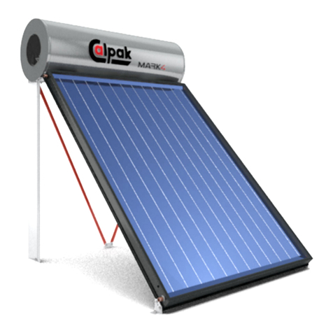
CALPAK X-FLOW User manual

OPERATION
MANUAL
Ultratank Calpak X-FLOW
Δt = 1
The technology we have developed permits the
transmission of water from the tank to the
stainless hot water exchanger, with a temperature
difference of only 1 degree. This means rapid
achievement of the desirable temperature and a
steady flow of hot water for consumption.
www.calpak.gr
η
th
= 99%
The Calpak X-FLOW tank produces the hot water
that you need, with a 99% efficiency rate. This
means that the energy source is fully used, thus
saving you a lot of money.
ΕPO PATENTED
LAB MEASUREMENTS
TECHNOLOGY
FOR EFFICIENCY BY
“DEMOKRITOS”


Ultratank CALPAK X-FLOW
Dear Customer,
Thank you for your preference for our products. Its leading technology, in conjunction with its
functionality and reliability, makes it the most efficient solution for hot water management.
The product comprises the following main components:
• Hot water tank with internal stainless exchanger providing hot water.
• Circulation pump (included in the counterflow kit)
• Control unit (included in the counterflow kit)
Detailed descriptions and instructions for these components are provided later on in the manual.
Instructions for this manual
The manual includes 5 chapters:
• Guarantees & Compliance
• Instructions for Safe Operation - Proper Use
• Product Description
• Instructions for Operation & Maintenance
• Uses and configuration
For more information:
Tel.: +30 210 9247250
Fax: +30 210 9231616
export@calpak.gr
www.calpak.gr
3


CONTENTS
1GUARANTEES & COMPLIANCE 6
1.1
HOT WATER TANK
....................................................................................................................................
6
1.2
CIRCULATION PUMP
.
...............................................................................................................................
7
1.3
CONTROL UNIT
.
........................................................................................................................................
7
2INSTRUCTIONS FOR SAFE OPERATION - PROPER USE 9
2.1
IN GENERAL
..............................................................................................................................................
9
2.2
INSTRUCTIONS FOR SAFE OPERATION
..............................................................................................
10
2.3
ELECTRICAL INSTALLATION OF OPTIONAL ACCESSORIES
.............................................................
10
2.4
WATER REQUIREMENTS
.......................................................................................................................
10
2.5
PRECAUTIONS IN THE DOMESTIC WATER CONNECTION
.
................................................................
10
3PRODUCT DESCRIPTION
11
3.1
GENERAL DESCRIPTION
.......................................................................................................................
11
3.2
CHARACTERISTICS OF ULTRATANK HOT WATER TANK
...................................................................
13
3.2.1
TABLE OF DISTANCES AND OTHER INFORMATION
...........................................................................
14
3.2.2
OPTIONS WHEN USING CALPAK X-FLOW ULTRATANKS
...................................................................
17
3.3
CIRCULATOR
..........................................................................................................................................
18
3.3.1
CIRCULATOR CONFIGURATION AND INSTALLATION OF 0,8 m³/H CALPAK X-FLOW
COUTERFLOW KIT (FOR 300LT TANK)
19
3.3.2
CIRCULATOR CONFIGURATION AND INSTALLATION OF 1.5 m³/H CALPAK X-FLOW
COUNTERFLOW KIT (FOR 500 LT, 1000 LT AND 2000 LT TANKS)
21
3.3.3.
CIRCULATOR CONFIGURATION AND INSTALLATION OF 3.0 & 4.5 m³/H CALPAK X-FLOW
COUNTERFLOW KIT (FOR 1000 LT TANKS)
24
3.3.4.
CIRCULATOR CONFIGURATION AND INSTALLATION OF 3.0 & 4.5 m³/H CALPAK X-FLOW
COUNTERFLOW KIT (FOR 2000 LT TANKS)
25
3.3.5
FAILURE WARNING PANEL
....................................................................................................................
28
3.4
CONTROL UNIT
.
......................................................................................................................................
28
3.4.1
INTRODUCTION TO CFA/3
.....................................................................................................................
28
3.4.2
CFA/3 INSTALLATION AND WIRING
.
......................................................................................................
30
3.4.2.1
GENERAL INSTRUCTIONS
.....................................................................................................................
30
3.4.2.2
CFA/3 INSTALLATION/REMOVAL
...........................................................................................................
31
3.4.2.3
CFA/3 CONNECTION AND WIRING
........................................................................................................
31
3.4.3
CFA/3 COMMISSIONING AND CUSTOMISATION
..................................................................................
33
4INSTRUCTIONS FOR OPERATION AND MAINTENANCE
37
4.1
OPERATION
.............................................................................................................................................
37
4.2
MAINTENANCE
.
.......................................................................................................................................
37
4.3
INSTRUCTIONS FOR USERS
.................................................................................................................
38
5USES AND CONFIGURATION
39
5.1
INDICATIVE USES AND CONFIGURATION
...........................................................................................
39
5.2
INDICATIVE CONNECTION OF MULTIPLE CALPΑK X-FLOW ULTRATANKS
......................................
41
5.3.A
INDICATIVE CONNECTION OF CALPAK X-FLOW ULTRATANK TO THERMAL PUMP
AND EXTERNAL BUFFER (FOR AMPLIFICATION OF THE DISCHARGING TIME)
41
5.3.B
INDICATIVE CONNECTION OF CALPAK X-FLOW ULTRATANK TO SOLAR COLLECTOR
AND EXTERNAL BUFFER (FOR AMPLIFICATION OF THE DISCHARGING TIME)
.
42
5.4
INDICATIVE RECIRCULATION CONNECTION OF THE CALPAK X-FLOW ULTRATANK
....................
42
5.5
QUESTIONNAIRE FOR THE ACCURATE ASSESSMENT OF THE COVERAGE
OF SPECIFIC NEEDS FOR DHW BY CALPAK X-FLOW
44
5

1
GUARANTEES & COMPLIANCE
The guarantee begins when the product is installed at the location of the final user. The legal sale
document or receipt will be proof of the installation date.
Our company guarantees the excellent quality of the materials and the sound manufacture of the
product. The guarantee covers all parts of the product and undertakes the responsibility of providing
spare parts to replace any components with manufacturing defects.
The guarantee does not cover parts damaged or rendered defective during transportation, by scale
which appear because of inadequate or wrong maintenance, or because of incorrect connection of the
safety valve with the discharge system. Also, it does not cover any damages not related to defective
materials or manufacturing defects, or other damages to third parties or assets in general.
The guarantee does not include cleaning, the regular maintenance of the equipment or the normal wear
of the device itself. Such interventions will be made upon request of the user, who will also pay the
respective cost.
There is no guarantee in the following cases:
• when non-authorised technical personnel intervene;
• when the installation does not comply with the applicable rules and instructions of the manufacturer;
• The user is unable to show the legal acquisition document to the authorised staff.
• when there is no serial number and proof of the date when the product was installed.
Make sure you have these at hand every time an intervention is required.
The product must be used and maintained in compliance with the manufacturer’s instructions for
operation and maintenance, and with the applicable national laws and local regulations.
1.1
HOT WATER TANK
There is a 5-year guarantee for the hot water tank.
The product to be installed must comply with the safety requirements of the EN 12828 standard.
As regards the hydraulic circuit of the hot water, the following standards must be observed.
- EN 1717 - Protection against pollution of potable water in water installations and general
requirements of devices to prevent pollution by backflow.
- EN806 - Specifications for domestic water installations (TRWI).
- National laws.
A necessary requirement for the safe operation of the product is the installation of an appropriate expansion
vessel. A competent engineer and/or installer must be responsible for the sizing of the expansion tank.
4-bar valves are required. It is suggested to use an automatic water filling device, in order to ensure
stable hydraulic pressure.
6

1.2
CIRCULATION PUMP
The circulation pump comes with a 2-year guarantee.
1.3
CONTROL UNIT
The control unit comes with a 2-year guarantee.
CE DECLARATION OF CONFORMITY
(in accordance with Directives 2004/108/EC and 2006/95/EC)
This Declaration certifies that the product complies with the requirements of Directives 2004/108/EC
and 2006/95/EC (Directive on electromagnetic compatibility and Directive on the harmonisation of the
laws of Member States relating to electrical equipment designed for use within certain voltage limits),
and certifies that the information included in the product’s technical file are true.
Standards applied by the manufacturer:
EN 55022: 2010 and CISPR 22: 2008
EN 55024: 2010 and CISPR 24: 2010
EN 61000-4-2: 2009 and IEC 61000-4-2: 2008
EN 61000-4-3: 2006+A1: 2008 +A2: 2010 IEC 61000-4-3:2006+A1: 2007+A2: 2010
EN 61000-4-8: 2010 and IEC 61000-4-8: 2009
Year when the CE marking was added: 2015
Find below a model of the marking on the control unit and the safety marking affixed on visible
places of the electrical panel.
(on the front of the device)
(where the ground wire is installed)
7

DATE OF PURCHASE:
DATE OF INSTALLATION:
TYPE:
CFA/3
SN:
CFA/3xxxxx
Un 230 V
In 20 mA
50 Hz
IP 20
FOR INTERNAL INSTALLATION
AND USE
(on the front of the device)
The device must not be used next to or mounted on top of other devices. If it is necessary
to use the device next to or on top of other equipment, the device must be checked to verify
that it functions properly in such configuration. When used in a very humid or hot
environment, increased device emissions or lower immunity may be observed.
(on the front of the device)
General Terms
• Marking of electronic device
The device bears appropriate marking from its manufacturer.
• Industrial mark/Trademark
Available on the marking of the product
• Product Assembly
In line with the manufacturer’s procedures
• Instructions for installation and maintenance
Provided by the manufacturer inside or on the packaging of the product
• Protection against contact
Satisfactory
• Temperatures, arcs or radiation which may cause
danger None identified
• Insulation of electronic equipment
There are no uncovered parts in the device.
• Protection from dangers to the device which may be caused by external factors
• Mechanical resistance of the kit/mechanical parts
The mechanical resistance of the plastic kit where the electronic material and the electrical
circuit are placed is deemed adequate.
• Ambient conditions
The device is always installed indoors, in a secure place.
• Overload conditions
Results based on the testing of the device.
8

2
INSTRUCTIONS FOR SAFE OPERATION - PROPER USE
2.1
IN GENERAL
In this manual, you will find safety instructions which you must follow to ensure your own safety and
to protect the product and the equipment connected to it. The instructions are accompanied by a
warning triangle and, depending on the level of risk, they are divided into the following categories.
!
DANGER
This means that failure to implement protective measures may result in death, serious bodily injury or
material damage.
!
WARNING
This means that failure to implement protective measures may result in serious bodily injury or material
damage.
!
CAUTION
This means that failure to implement protective measures may result in bodily injury or material damage.
NOTE
A piece of information particularly significant for understanding and operating the device.
The successful and safe operation of the device depends on the proper transportation, storage,
setting, installation, operation and maintenance of the device.
The product may be used only as a water heater and only in conformity with the information provided
in this manual.
Any other use besides the intended one is considered inappropriate. The installer is the only person
responsible for any damage. The operation of the system also includes compliance with maintenance
and the terms of inspection. The spare parts must comply with the technical standards set by the
manufacturer.
9

2.2
INSTRUCTIONS FOR SAFE OPERATION
• The installation, connection and initial start-up should only be undertaken by authorised and
trained installers.
• Disconnect the power supply before you start doing any work on the device.
• Make sure that all the safety valves comply with the requirements of standard EN 12828 for
connection with the heating side and standard EN 12897 for the water side.
2.3
ELECTRICAL INSTALLATION OF OPTIONAL ACCESSORIES
• Before any works on live parts, disconnect the power supply.
• Electrical installations may be undertaken only by specialised electricians and in line with the
corresponding regulations.
• For each wired power connection, install a separate release system which complies with standard
EN 60335-1, for all pole disconnect switches.
• Compare the voltage indicated on the sign with the supply voltage before connection to the
electricity network.
2.4
WATER REQUIREMENTS
Please comply with the regulations on the prevention of corrosion and deposition.
In areas with “hard” water, you must use a suitable water management system (as provided for in
national legislation). More specifically, the water must have the following values.
Total
Total
Description
pH
dissolved
Chlorine
Magnesium
Calcium
Sodium
Iron
Hardness
solids
Maximum
6.5 -
acceptable
600mg/l
150mg/l
300mg/l
10mg/l
20mg/l
150mg/l
1mg/l
levels
9.0
2.5
PRECAUTIONS IN THE WATER CONNECTION
During the operation of the product, and in combination with the temperature of the charging source,
the temperature of the hot water may exceed 60 °C. Systems protecting from burns (such as a hot
water mixing device) should be included during the installation of the system.
Use a pressure reducer if cold water connection pressure exceeds 6 bar.
10

3 PRODUCT DESCRIPTION
DEFINITION FOR ULTRATANK
“A tank through which hot water passes, with the possibility of connection to
multiple charging sources. Its exceptional property is the ability to provide a large
and stable flow of hot water, after being charged at a temperature exceeding the
desired hot water temperature by only one degree, thus resulting in a more
economical operation of power sources (heat pump, boiler, solar panels, etc.)
and exerting less strain on the system. It may also be used as a buffer tank for
space heating.
3.1
GENERAL DESCRIPTION
The main use(s) of the product is(are) to provide hot water for use and/or hot water for space heating
purposes, as well as for any other heating-provision process, by adding the appropriate equipment.
The product comprises a thermally insulated steel tank filled with a heat transfer fluid (usually water),
a heat exchanger, a counterflow circulation pump and a control unit with the respective temperature
sensors.
In the conventional configuration of the product (Figure 1), we see the following:
• Side inlet (position E), for the supply of cold water to the stainless heat exchanger.
• Outlet of the stainless exchanger on the upper part of the tank (position Τι), for the supply of hot
water.
• Peripheral holes for the installation of temperature sensors and connection with hydraulic circuits
of thermal sources (conventional boiler circuit, heat pump circuit, solar collectors circuit) and of
electric resistance.
• Internal exchanger for the transmission of thermal energy.
• Counterflow circulation pump to forward the water of the exchanger and transfer thermal energy
to the water.
• Control unit responsible for adjusting the temperature of the hot water to the desirable levels. This is
achieved thanks to the automatic control of the operation of the counterflow circulation pump.
An algorithm is used for the operation of the control unit, which takes into account the
desirable temperature for the hot water and the desirable temperature for the hot water tank,
indicating each time the corresponding point of operation of the electromechanical devices.
NOTE
The hydraulic circuit of the conventional boiler, the solar circuit, the circuit of the heat pump
and/or any additional thermal source circuit may operate independently of one another and/
or simultaneously.
NOTE
The product generates hot water at the desirable temperature, with minimal difference from
the temperature of the water in the tank. With a separate hydraulic hot water circuit from the
water stored in the tank, we manage to tackle the hygiene problem and, in particular, the
NOTE
growth of bacteria (see Legionella).
11

E1
Τ
ι
E2
L
F
Α
G
Β
H
C
M
I
S
Ν
D
K
J
P
R
E1
Τ
ι
E2
L
F
Α
G
Β
H
C
M
I
S
Ν
D
K
J
P
R
Ultratank X
-
FLOW
Ultratank X
-
FLOW plus
Figure 1
Conventional product
configuration
Calpak
Calpak
Calpak
Calpak
X
-
FLOW
X
-
FLOW
X
-
FLOW 0,8
X
-
FLOW 1.5
POSITION
DESCRIPTION
1.5/3/4,5
1.5/3/4,5
Dt1 /300lt
Dt1 /500lt
Dt1 /1,000 lt
Dt1 /2,000 lt
(plus)
(plus)
(plus)
(plus)
Α
Free flow
3/4”
1-1/2”
1-1/2”
2”
B
Free flow
3/4”
1-1/2”
1-1/2”
2”
C
Free flow/Inlet of exchanger of solar
3/4”
1-1/2”
1-1/2”
2”
collectors in the “plus” model
D
Free flow/Outlet of exchanger of solar
3/4”
1-1/2”
1-1/2”
2”
collectors in the “plus” model
E1
Cold water inlet (stainless steel)
3/4”
1”
1-1/2”
1-1/2”
E2
Hot water outlet (stainless steel)
3/4”
1”
1-1/2”
1-1/2”
F
Counterflow pump suction
3/4”
1-1/2”
1-1/2”
2”
G
Free flow
3/4”
1-1/2”
1-1/2”
2”
H
Free flow
3/4”
1-1/2”
1-1/2”
2”
I
Free flow
3/4”
1-1/2”
1-1/2”
2”
J
Free flow
3/4”
1-1/2”
1-1/2”
2”
K
Free flow
3/4”
1-1/2”
1-1/2”
2”
L
Temperature sensor
1/2”
1/2”
1/2”
1/2”
M
Temperature sensor
1/2”
1/2”
1/2”
1/2”
N
Temperature sensor
1/2”
1/2”
1/2”
1/2”
P
Outflow
1”
1”
1”
2”
R
Heating element/
1-1/2”
1-1/2”
1-1/2”
1-1/2”
Recommended heating element
4KW
4KW
6KW
9KW
12
S
Side inspection flange
-
-
Ø508
Ø508

3.2
CHARACTERISTICS OF ULTRATANK HOT WATER TANKS
• Manufactured from high-quality steel
• Robotic welds
• Tank’s maximum pressure: 6 bar
• Maximum pressure of stainless DHW speed-alternator: 10 bar
• Maximum operating temperature: 95°C
• Integrated counterflow exchanger with a 99% energy efficiency (for fresh water)
• Stable charging exchanger (in the “plus” models)
• Possibility to connect up to 4 energy sources
• Large maintenance port Φ508
• Removable polyurethane insulation
exchanger’ s power
exchangerperformance
Heat exchanger’s power [kW]
Heat
Hea
Supply, Q [Ι/h]
Figure 2
η
th
=99%
(source: National Centre for Scientific Research, Demokritos)
ChargingCharging–TankCalpak-TnkXCalpak-FLOW 2000gse 2000ltMO lttemperaturesMOtemperaturesvstank 2000vstankltwith2000staticlt withheat staticexchangerheat5,4 cm
2
Production temperature
exchanger
inthe
5,4
heat
m2
exchanger 60°C
TEMPERATURE [
O
C]
Figure 4
MINUTES
Calpak X
-
FLOW
Tank with static heat exchanger 5,4m
2
Figure 3
ΔT=1
(
source: National Centre for
Scientific Research, Demokritos
)
- Supply temperature
- Tank΄s average temperature
- Counterflow temperature
Tm exp tank: Container΄s
average temperature
Trec: Hydraulic circuit
temperature
Τhe OUT: Hot water supply
temperature
ADVANTAGES OF CALPAK X-FLOW ULTRATANK
• Top performance rate (99%) for an additional 25% in energy savings
• Almost zero deviation between charging and supply temperature (ΔΤ=1)
• Very fast charging of the ultratank compared to conventional tanks (see figure 4)
• Desirable consumption temperature achieved very fast
• Protection from the Legionella bacterium, thanks to the stainless steel continuous flow alternator
• Steady hot water supply at precise desirable temperature
• Long life span, minimum maintenance cost
• Easy installation or replacement of existing tank
• Easy system expandability with new energy sources
• Ideal use with heat pump and/or solar panels
• Applicable in homes, hotels and commercial buildings
13

3.2.1
TABLE OF DISTANCES AND OTHER INFORMATION
Calpak
Calpak
Calpak
Calpak
X-FLOW 0,8
X-FLOW
X-FLOW
X-FLOW
DISTANCES
DESCRIPTION
Dt1/300
1.5 Dt1/500
1.5/3/4,5
1.5/3/4,5
(plus)
(plus)
Dt1/1000
Dt1/2000
(plus)
(plus)
NOMINAL CAPACITY (lt)
300
500
1000
2000
NET CAPACITY (without the heat exchanger for
279,7 /
469.2 /
883.6 /
2027.6 /
the PLUS models) (lt)
(269,6)
(450.2)
(855.6)
(1997.6)
Diameter of the stainless speed-alternator
DN20
DN25
DN40
DN40
Max. operating pressure of the stainless speed-
10 bar
10 bar
10 bar
10 bar
alternator
Weight (Kg) of empty Calpak X-FLOW 0,8 tank
109 / (119)
Weight (Kg) of empty Calpak X-FLOW 1.5 tank
-
159 / (193)
239 / (289)
402 / (459)
Weight (Kg) of empty Calpak X-FLOW 3.0 tank
-
-
244 / (294)
407 / (464)
Weight (Kg) of empty Calpak X-FLOW 4.5 tank
-
-
254 / (304)
417 / (474)
Height of tank (without the insulation)
1680
1700
2100
2100
Height of tank
1740
1800
2200
2200
Total height of tank (with the speed-alternator)
1940
1950
2350
2350
Outer diameter of tank (without the insulation)
520
640
800
1200
Outer diameter of tank (with the insulation)
720
840
1000
1400
Hot water tank ventilation
Polyurethane insulation thickness (mm)
100
100
100
100
Thermal losses (kWh/24h)
1.6
1.8
2.1
2.5
Sheet thickness (mm)
2.5
2.5
3
4
Capacity of charging heat exchanger
-- / (8)
-- / (15)
-- / (20)
-- / (24)
(for PLUS models) (lt)
Surface area of charging heat exchanger
-- / (1.10)
-- / (1.90)
-- / (2.80)
-- / (6.10)
(for PLUS models) (m
2
)
inox
A
Free flow
1465
1460
1550
1580
B
Free flow
1270
1270
1550
1590
C
Free flow/(Inlet of heat exchanger of solar
915
915
920
990
collectors in the “plus” model)
D
Free flow/(Outlet of heat exchanger of solar
360
360
375
420
collectors in the “plus” model)
F
Counterflow pump suction
1465
1460
1730
1780
G
Free flow
1465
1460
1750
1780
H
Free flow
1270
1270
1550
1580
I
Free flow
910
915
920
990
J
Free flow
360
360
375
420
K
Inlet of charging heat exchanger
360
360
375
430
L
Temperature sensor
1465
1460
1730
1780
M
Temperature sensor
915
915
920
990
N
Temperature sensor
440
480
500
545
P
Outflow
40
40
40
40
R
Heating element
340
320
380
430
Note:
- The values are indicated in millimetres (mm).
- The distances are measured from the ground
14

Figure 5.1 Pressure drop at the 0.8 m³/h DHW speed-alternator
Pressure drop [bar]
Supply rate [lt/h]
Figure 5.2 Pressure drop at the 1.5m³/h DHW speed-alternator
15

Pressure drop [bar]
Supply rate [lt/h]
Figure 5.3 Pressure drop at the 3m³/h DHW speed-alternator
Pressure drop [bar]
Supply rate [lt/h]
Figure 5.4 Pressure drop at the 4.5m³/h DHW speed-alternator
16

3.2.2
OPTIONS WHEN USING CALPAK X-FLOW ULTRATANKS
Regarding the dimensioning of the tank, Calpak suggests:
A Calpak X-FLOW with a 1,500 lt/h (1.5 model) supply heat exchanger can cover the needs of up to
25 rooms, assuming that:
1. The peak in demand lasts 1.30 hours or more, with uniform distribution.
2. Each shower lasts 20 minutes.
Obviously, this is not an absolute calculation, because a different approach may be required depending on
the needs of the project and the estimations of each engineer.
Indicative charts on the coverage of peak demand in DHW at the desirable temperature
Change of average temperature of the device
temperature
(°C
)
Change of average temperature of the device
temperature
(°C
)
Change of average temperature of the device
temperature
(°C
)
*Note:
Calpak X-FLOW
SCENARIO 1:
a. A & B category hotel open throughout the year, Climate
Zone A
b. 40 persons (60lt/person/day)
c. Water temperature = 48 °C, peak = 1.5
hours, concurrency = 50%, tank = 2000 lt
d. 16kW heat pump, source start-up and shutdown
temperature: 54 °C and 55 °C respectively.
e. Month of reference: July
Duration of peak coverage by Calpak X-FLOW = 1:31:00
Duration of peak coverage by a conventional tank in the
same conditions = 0:50:00
minutes
SCENARIO 2:
a. A & B category hotel open throughout the year, Climate
Zone A
b. 40 persons (60 lt/person/day)
c. Water temperature = 48 °C, peak = 1.5
hours, concurrency = 35%, tank = 2000 lt
d. 16kW heat pump, source start-up and shutdown
temperature: 54 °C and 55 °C respectively.
e. Month of reference: April
Duration of peak coverage by Calpak X-FLOW = 1:27:00
Duration of peak coverage by a conventional tank in the
minutes
same conditions = 0:51:00
SCENARIO 3:
a. A & B category hotel open throughout the year, Climate
Zone A
b. 40 persons (60 lt/person/day)
c. Water temperature = 45 °C, peak = 1.5 hours,
concurrency = 50%, tank = 2000 lt
d. 16kW heat pump, source start-up and shutdown
temperature: 54 °C and 55 °C respectively.
e. Month of reference: July
Duration of peak coverage by Calpak X-FLOW = 3:24:00
Duration of peak coverage by a conventional tank in the
minutes
same conditions = 1:20:00
Conventional tank with heat exchanger performance 70%
Calpak has developed specialised
software to ensure with accuracy the coverage of hot water
needs (DHW) in each individual case. If you wish, you may fill in the questionnaire (page
comprehensive
NOTE
technical report from our company, detailing with precision the function of the selected tank in
relation to the consumption profile of your client.
17

3.3
COUNTER FLOW KIT
IN GENERAL
The counterflow kit is consisted of a circulation pump (which type and size vary according to the type
and size of the corresponding DHW speed-exchanger), a special controller, a stainless steel pipe and
several fittings that are necessary to complete the counterflow closed circuit. The circulation pump is
designed to be installed in heating systems. The maximum circuit pressure is 10 bar. The maximum
and minimum temperature of the circulating liquid is 110°C and -10°C, respectively. The circulating
liquid may be either clean water or a mixture of clean water and antifreeze liquid suitable for central
heating systems. The maximum environment temperature in which the circulation pump functions
properly is 35°C (for water at a temperature of 110°C) and higher than the dew point of the circulating
liquid (to avoid condensation). To prevent burns, avoid contact with the circulation pump and the
circulating liquid during operation. The circulation pump must not be used to transfer fuels or
flammable liquids or be used in flammable environment. The curves indicating the performance of
pumps appear in the relevant charts. For draining purposes, there are labyrinths in the pump’s motor.
When insulating, do not cover the labyrinths; otherwise, you may cause serious damage.
ELECTRICAL CONFIGURATION
The electrical connection must be undertaken by specialised individuals. The connection to power is
shown in chart 4 of 3.3.5. For the electrical connection of the pump with power (1Χ230V, 50Hz), an
appropriate connecting cable must be used (3G 1mm
2
, H05RR- F). Before disconnection, make sure
that all the necessary measures are taken in line with the applicable regulations. The power cord must
be connected in such a way that it cannot come in contact with parts of the shell, because of the high
temperature of the shell.
!
WARNING
This device is not intended to be used by people (including children) with reduced physical or mental
capabilities, people who lack the necessary experience and knowledge, unless they are supervised
or instructed on the use of the device by a person responsible for their safety. Children must be
supervised so that they don’t play with the device.
MAXIMUM OPERATION TEMPERATURES
Water temperature in the circuit (°C):
110
100
90
80
Maximum room temperature (°C):
35
50
60
70
SPEED ADJUSTMENT
The circulation pump’s speed may be adjusted with the speed switch on the circulation pump’s electric
box: to the left for minimum (min.) speed and to the right for maximum (max.) speed. It is suggested
that you adjust it to maximum speed.
18

3.3.1 CIRCULATOR CONFIGURATION AND INSTALLATION OF 0,8 m³/h
CALPAK COUNTERFLOW KIT
(with 300 LT tank)
OUT
13
Position of sensor
DHW
in Ts Out design
11
12
03
01
POSITION FOR 1/2”
VENTILATOR OF TANK
02
01
04
CFA/3
05
Calpak X
-
FLOW 0,8/300lt (plus)
08
05
10
05
06
07
SET
09
03
Position
Description
Quantity
Unit
01
Fitting DN20X3/4” M
2
pc
02
Flexible pipe 316L DN20
0,5
m
Insulation of flexible pipe 9*22
0,5
m
03
Spherical switch ¾”
2
m
04
Compression fitting AM 1-1/4”*3/4
1
pc
05
Circulation pump Wilo Yonos Para 30/7.0
1
pc
06
Compression nipple 1-1/4”3/4”
1
pc
07
Angle M/F ¾”
1
pc
08
Controller CFA/3 with two sensors
1
pc
09
Connection point counterflow pump section
_
_
(see F image 1/p. 13)
10
Ultratank Calpak X-FLOW
1
pc
11
Rotation venting valve
1
pc
12
Bushing nipple ½”*3/8*
1
pc
13
Bushing ¾” with sensor hose 8 mm
1
pc
19
Note:
the above drawing is valid for the
Calpak X
-
FLOW 0,8/300 (plus)

TECHNICAL DATA OF THE COUNTERFLOW 0,8 m³/h CIRCULATION
PUMP HYDRAULIC CONNECTION AREA
DIMENSIONS
Thread
Total length
Dimensions
(mm)
(mm)
10
L1
G2”
180
90
POWER
Thread
Dimensions (mm)
Energy efficiency (EEI Index)
<= 0,20
Maximum manometer height
7,3 m
Maximum flow
65
Speed (rmp)
800 / 4660
Power consumption (1-230V)
3–45W
20
ELECTRICAL CONNECTION
Central supply
1 ~ 230V + 10% / =15%, 50 / 60 Hz (IEC 60038 standard voltage)
Table of contents
Other CALPAK Water Heater manuals
Popular Water Heater manuals by other brands

Zodi
Zodi Stove Top Series Instructions for use

Myson
Myson MPE 228 Quick manual

A.O. Smith
A.O. Smith BTX-80 SERIES 100 instruction manual

Rinnai
Rinnai Infi nity Solar 20 Operation and installation manual

Sime
Sime MINI 12 OF Erp user manual

Lochinvar
Lochinvar KSA040KDB Installation Instructions and Use & Care Guide

State Water Heaters
State Water Heaters FVIR Installation Instructions and Use & Care Guide

GSW
GSW WATER HEATING Installation and operating instructions

Saunier Duval
Saunier Duval FE 300/3 MR operating instructions

Cadet
Cadet The Com-Pak Bath Heater CB103T owner's guide

State Water Heaters
State Water Heaters ULTRA FORCE SUF-130-300 Operator's manual

fothermo
fothermo CPVB-10 instruction manual