Caltta PR900 User manual

secret▲
All rights reserved.No spreading abroad without permission of Caltta.
2
PR900
Edition
Date
Author
Reviewer
Remarks
V1.0
2019/3/20

secret▲
All rights reserved.No spreading abroad without permission of Caltta.
3
Legal Information
© 2019 Caltta Technologies. All rights reserved.
2019 Copyright Caltta Technologies Co.,Ltd. All rights reserved
Copyright statement:
The copyright of this document belongs to Caltta Technologies Co.,Ltd. Text contains
proprietary information owned by Caltta Technologies Co.,Ltd., without the written
permission of Caltta Technologies Co.,Ltd., any unit or individual shall not use or leak any
document and pictures, this document contains tables, picture, data and other
information.
The information in this document contains the development progress of Caltta
Technologies Co.,Ltd. products and technology will continue to update, Caltta
Technologies Co.,Ltd. would not notice such information updates.
User instructions
Any use of radio transmitters within government controlled areas without the
authority's permission is forbidden by the law.
Penalties will be given on those who use transmitters illegally.
Maintenance can only be carried out by professionals.
Disclaimer
During the preparation process of this manual, we sought for accuracy and completeness
of its contents. Should there be any errors or omissions, we will not bear any responsibility.
Due to continuous development of technology, we reserves the right not to give further
notice on changes of design and specifications of our products.
RF radiation information
This product only meets the application requirements on RF energy radiation. The user
must be acutely aware of the hazards brought by RF radiation, and able to take
corresponding measures to meet the prescribed requirements of RF radiation.

secret▲
All rights reserved.No spreading abroad without permission of Caltta.
4
Catalog
1 Unpacking and Checking............................................................................................................6
2 Radio Overview............................................................................................................................6
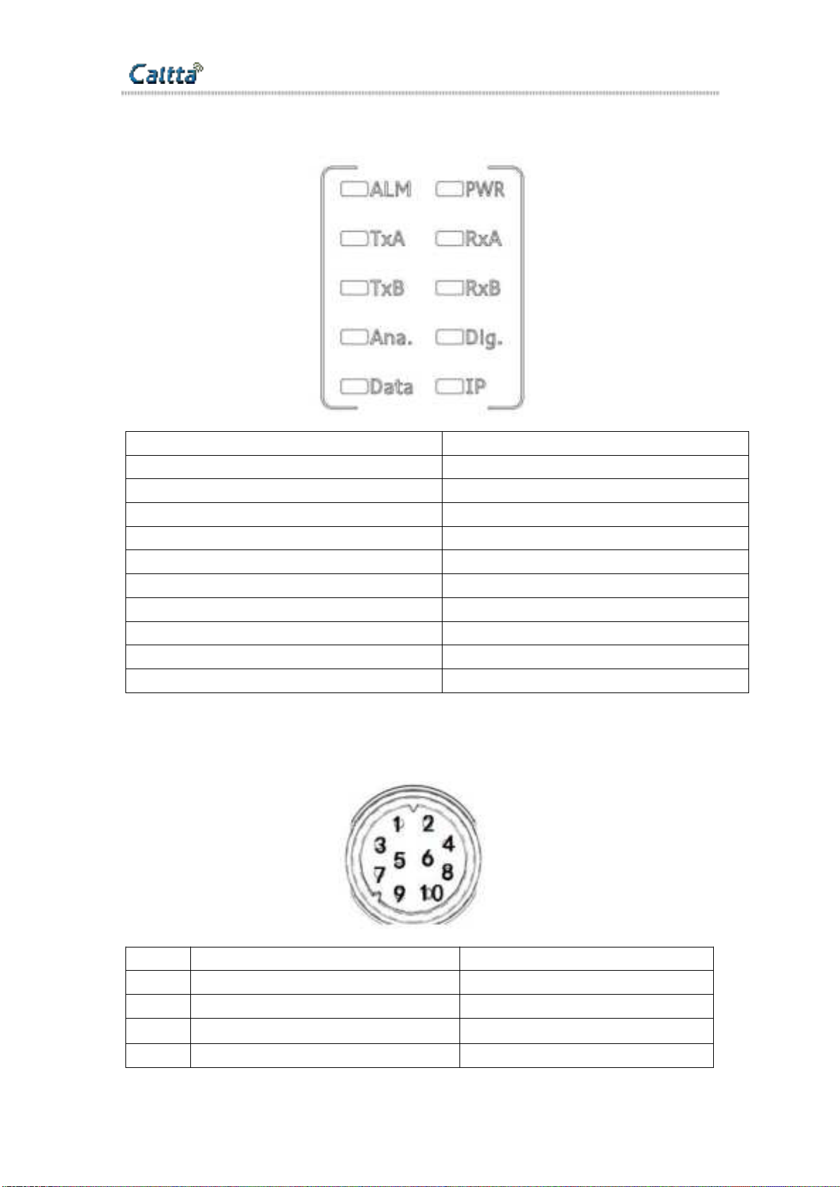
2.1 LED Indicators................................................................................................................... 7
2.2 MMP Connector................................................................................................................. 7
2.3 MAP Connector..................................................................................................................8
2.4 AC Cable Connector.......................................................................................................... 9
2.5 DC Connector.....................................................................................................................9
2.6 Power ON/OFF Button.......................................................................................................9
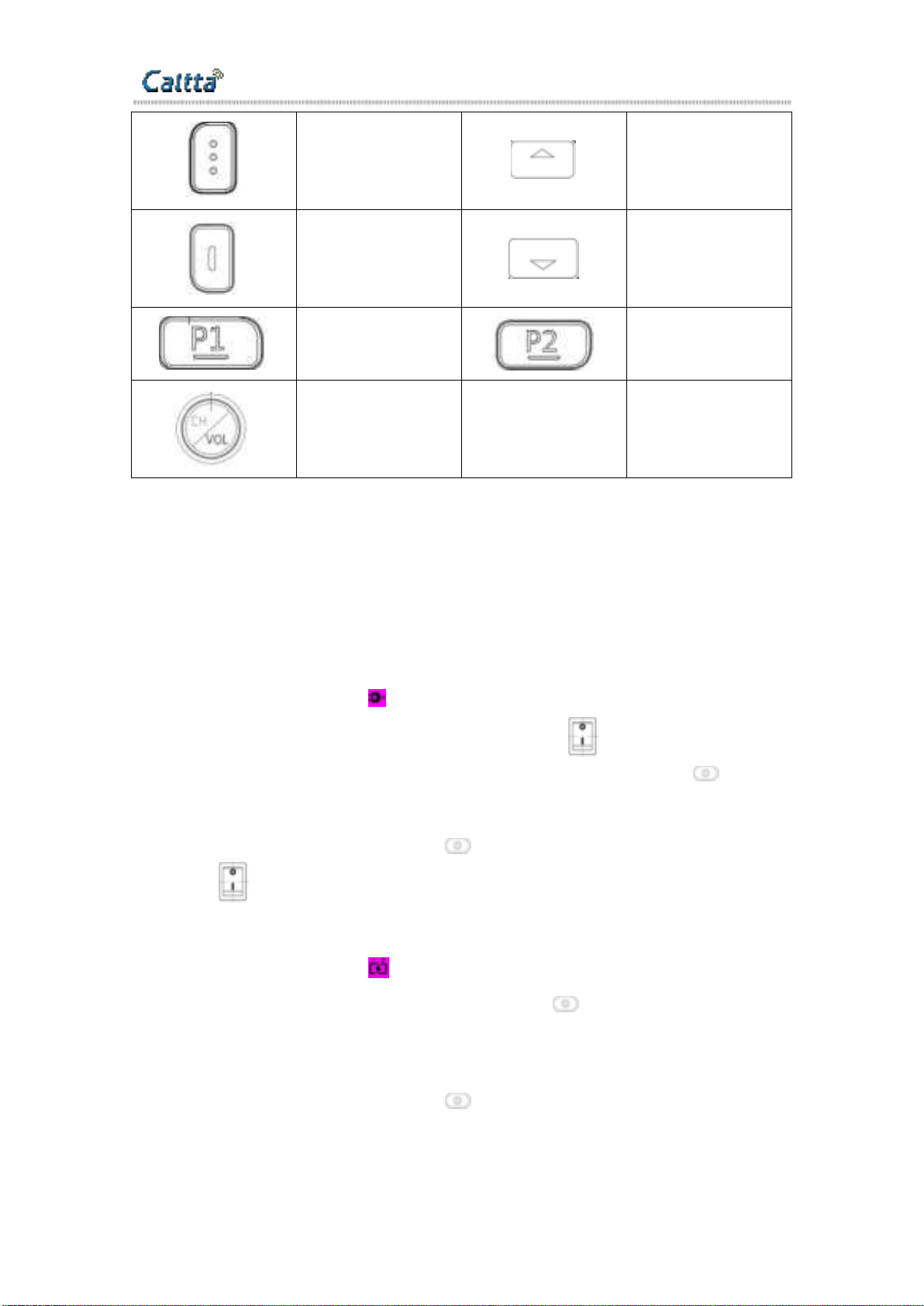
2.7 Operation Button................................................................................................................ 9
3 Operations.................................................................................................................................. 10
3.1 Powering On/Off.............................................................................................................. 10
3.1.1 AC Power Supply ....................................................................................... 10
3.1.2 DC Power Supply .......................................................................................10
3.2 Voice and Data Transfer.................................................................................................. 11
3.3 IP Connecting................................................................................................................... 11
3.4 Warning............................................................................................................................ 11
4 CPS-Menu.................................................................................................................................. 11
4.1 File 11
4.2 Model................................................................................................................................12
4.3 Program............................................................................................................................ 13
4.4 Tools................................................................................................................................. 15
4.5 View..................................................................................................................................16
5 Common Setting........................................................................................................................ 16
5.1 Common Setting-General Setting.................................................................................... 16
5.1.1 Common Setting-General Setting-Common Setting........................................ 16

secret▲
All rights reserved.No spreading abroad without permission of Caltta.
5
5.1.2 Common Setting-General Setting-Digital Setting............................................ 20
5.1.3 Common Setting-General Setting-Analog Setting............................................22
5.2 Common Setting-UI Setting.............................................................................................23
5.2.1 Common Setting-UI Setting..............................................................................23
5.2.2 Common Setting-UI Setting-Backlight.............................................................25
5.2.3 Common Setting-UI Setting-Button................................................................. 25
5.2.4 Common Setting-UI Setting-Menu................................................................... 27
6 Conventional Setting................................................................................................................. 28
6.1.1 Conventional Setting-Password........................................................................ 28
6.1.2 Conventional Setting-Zone............................................................................... 29
6.1.3 Conventional Setting-Channel-Digital Channel............................................... 29
6.1.4 Conventional Setting-Channel-Analog Channel...............................................30
6.1.5 Conventional Setting-Multi CTC/CDC............................................................ 32
6.1.6 Conventional Setting-Contact........................................................................... 32
6.1.7 Conventional Setting-Network-Network.......................................................... 33
6.1.8 Conventional Setting-Network- Local Access Management............................35
6.1.9 Conventional Setting-Network-Multisite Access Management....................... 35
6.1.10 Conventional Setting-Network-Application Programming Interface............ 35

secret▲
All rights reserved.No spreading abroad without permission of Caltta.
6
1 Unpacking and Checking
Please unpack carefully and check all the items listed in the following table before
discarding the packing material. If any damage or loss occurs during shipment, please
contact your dealer.
Standard Accessories
2 Radio Overview
No.
Part Name
No.
Part Name
1
Cooler
9
100~240V AC Cable Connector
2
Channel/Volume Button
10
13.6V DC Connector
3
LCD
11
USB Connector
4
Function Button
12
Network Connector(IP)
5
Front Panel LED Indicators
13
MAP Connector
6
Power ON/OFF Button
14
Rx Connector
7
MMP Connector
15
Tx Connector
8
AC Power Indicators
16
GND Screw
Item
Quantity
Repeater
1
Instruction Manual
1
Power cable
1

secret▲
All rights reserved.No spreading abroad without permission of Caltta.
7
2.1LED Indicators
Indicators
Description
ALM
Alarm indicator
PWR
Power indicator
TXA
Slot 1 transmitting indicator
RXA
Slot 1 receiving indicator
TXB
Slot 2 transmitting indicator
RXB
Slot 2 receiving indicator
Ana
Analog mode indicator
Dig.
Digital mode indicator
Data
Repeater signal indicator
IP
IP interconnection status indication
2.2MMP Connector
PIN
Indicators
Description
1
MMP10_Mic
mic
2
MMP10_Spk
speaker
3
MMP10_PTT
External PTT,low level is effective
4
MMP10_Hook
Hang up signal

secret▲
All rights reserved.No spreading abroad without permission of Caltta.
8
5
GND
GND
6
MMP10_USB_D+
USB_D+ signal
7
MMP10_USB_D-
USB_D- signal
8
MMP10_USB_Vbus
USB_VBUS +5V DC power
9
MMP10_DET1
Accessory detection 1
10
MMP10_DET2
Accessory detection 2
2.3MAP Connector
PIN
Indicators
Description
1
RX_UART_RXD
RX UART RXD
2
RX_UART_TXD
RX UART TXD
3
Tx_Audio1
Transmit audio input for slot 1 in digital mode
4
Audio_GND
Audio GND
5
GPIO1
Program input
6
GPIO2
Program output
7
GPIO3
Program input/output
8
GPIO4
Program input/output
9
GPIO5
Program input/output,Default for Emergency function
10
Slot1_Audio
Received audio output for time slot 1 in digital mode
11
Slot2_Audio
Received audio output for time slot 2 in digital mode
12
Tx_Audio2
Transmit audio input input for time slot 2 in digital mode.
13
NC
Undefined
14
GND
GND
15
VBUS
+5V DC power,max current 500mA
16
USB_D+
USB_D+ signal
17
USB_D-
USB_D- signal
18
USB_GND
USB GND
19
TX_UART_TXD
TX UART TXD

secret▲
All rights reserved.No spreading abroad without permission of Caltta.
9
20
TX_UART_RXD
TX UART RXD
21
TDMA
Transmit trigger signal
22
ACC_MAP_DET1
It is used for test
23
ACC_MAP_DET2
It is used for test
24
SWB+
Output the system supply voltage,max current 1000mA
25
Ext_Alarm
Programmable alarm output,Output the system supply
voltage,max current 300mA
26
Power_GND
Power GND
2.4AC Cable Connector
Press I to power on the AC power.Press O to power off the AC power.
2.5DC Connector
2.6Power ON/OFF Button
Power ON/OFF the repeater
2.7Operation Button
Indicators
Description
Indicators
Description

secret▲
All rights reserved.No spreading abroad without permission of Caltta.
10
Return
Up
Menu/Confirm
Down
Programmable
button 1
Programmable
button 2
Channel/Volume
Switch
3 Operations
3.1Powering On/Off
3.1.1 AC Power Supply
When the repeater is turned off , press the back panel (AC power switch )to turn
on the power,the AC power indicator lights up, and then press the front panel (power
button) to power on the repeater .The “PWR” indicator lights up, and the LCD will enter the
operation interface after the system is working normally.
When the repeater is turned on, press (power button) to turn off the repeater ,
and press (AC power switch )to turn off the AC power.
3.1.2 DC Power Supply
When the repeater is turned off ,press the front panel (power button) to power on
the repeater .The “PWR” indicator lights up, and the LCD will enter the operation interface
after the system is working normally.The “PWR” indicator lights up, and the LCD will enter
the operation interface after the system is working normally.
When the repeater is turned on, press (power button) to turn off the repeater .

secret▲
All rights reserved.No spreading abroad without permission of Caltta.
11
3.2Voice and Data Transfer
The receiving and transmitting frequency are different on the repeater. Repeater will
turn the weak receiving signal into strong transmitting signal and transmit on the same
channel. When transmitting, the “DATA”light is on. If it is analog signal, the “Ana.”light on.
if it is digital signal, the “Dig.”light flashes. The receiving and transmitting frequency and
CDCSS/CTCSS can be set by CPS.
An analog channel or a smart analog/digital detecting channel can be programmed
with one group of CDCSS/CTCSS encoding and decoding list. When receiving
CDCSS/CTCSS on the channel, repeater will transmit according to preprogrammed
CDCSS/CTCSS encoding and decoding list.
3.3IP Connecting
Default IP address:192.168.1.100. Application update, parameters configuration and
second development can be made through this port.
3.4Warning
When unusual situation happens, the alarm indicator ”ALM” will be enlightened. For
example, when Receiving Frequency unlocks, the warning light will flash once one second;
Transmitting frequency unlocks, the warning light will flash once two seconds; When both
transmitting and receiving frequency unlock, the alarm indicator ”ALM” will stay light on.
When the repeater occurs unusual situation, please let the related professional to
check and recover the repeater.
4 CPS-Menu
4.1File
Files refer to the configuration files of your Repeater, which are in .grd format.
The File menu includes the following functions:
Submenu
Description
Shortcut
Key
New
This function clears all the data in the current
window, restores it to the default setting, and
creates a new file.
Ctrl+N
Open
This function opens a data file from the hard disk
or other data media, for you to modify the file or
write it to your Repeater.
Ctrl+O

secret▲
All rights reserved.No spreading abroad without permission of Caltta.
12
Open
Template
Selecting the Open Template mode to open a file
can save the CPS configuration parameters that
are compatible with earlier versions and update
the earlier database versions to the version
corresponding to the current CPS.
Close
This function closes the configuration file in the
current window.
/
Save
This function saves the new file or modified file by
the current filename under the current path. The
file is saved in .grd format and must be saved in
this format.
Ctrl+S
Save As
This function saves the current file by a new name
under the specified path. The file is saved in .grd
format and must be saved in this format.
Ctrl+A
Print
This function prints programming data. After you
select this function, the Print dialog box is
displayed, in which you can set printing options,
such as the pages and number of copies, as
needed.
Ctrl+P
Preview
After you select this function, the print preview
window is displayed in the main window.
/
Print Setting
After you select this function, the Print Setup
dialog box is displayed.
/
Exit
This function exits the CPS.
/
4.2Model
Model Information: This function shows the models and the corresponding frequency
bands [MHz] in the configuration file. You can select a model as needed.

secret▲
All rights reserved.No spreading abroad without permission of Caltta.
13
4.3Program
The Program menu includes the following functions:
Submenu
Description
Shortcut
Key
Read
This function reads data from your Repeater. After
powering on your Repeater, connect it to a PC and select
Program > Read. The Read dialog box is displayed. Click
OK to read data. During the data reading process, a
progress bar is displayed to show the progress. After
programming data is read completely, a message box is
displayed, showing that data is read successfully.
Ctrl+R
Write
This function writes data into your Repeater. After
powering on your Repeater, connect it to a PC through a
USB cable and select Program > Write from the menu.
The Write dialog box is displayed. Click OK to write data.
During the data writing process, a progress bar is
displayed to show the progress. After programming data is
written completely, a message box is displayed, showing
that data is written successfully. Your radio will be
restarted automatically and then use the new configuration
data.
Ctrl+W
USB Port
This function allows you to select the port device for this
operation.
/
Restore
Factory
Defaults
This function restores all parameter settings of your
Repeater to the default values.
/
Clone
This function replicates the configured data to a target
Repeater. After powering on your Repeater, connect it to a
PC and select Program > Clone from the menu. The Clone
dialog box is displayed, asking you to select the target
/

secret▲
All rights reserved.No spreading abroad without permission of Caltta.
14
configuration file. Then, click OK to clone data. During the
cloning process, a progress bar is displayed to show the
progress. After cloning is completed, a success message
box is displayed. The target radio will be restarted
automatically and then use the new configuration data.
Note: The cloning process skips checking the ID , name,
account number, and password of your radio, and reads
and writes the password information.
Cloning is not allowed when the dialing rules for the clone
data are inconsistent with the radio data
Remote Read
This function reads data from your Repeater. select
Program > Remote Read. The Read dialog box is
displayed. Click OK to read data. During the data reading
process, a progress bar is displayed to show the progress.
After programming data is read completely, a message
box is displayed, showing that data is read successfully.
Remote Write
This function writes data into your Repeater. select
Program > Remote Write from the menu. The Write dialog
box is displayed. Click OK to write data. During the data
writing process, a progress bar is displayed to show the
progress. After programming data is written completely, a
message box is displayed, showing that data is written
successfully. Your radio will be restarted automatically and
then use the new configuration data.

secret▲
All rights reserved.No spreading abroad without permission of Caltta.
15
4.4Tools
The Tools menu includes the following functions:
Submenu
Description
Language
This function sets the language of the CPS.
Import DT Data
This function is not supported on Repeater Model.
Export DT Data
This function is not supported on Repeater Model.
Import DG Data
This function is not supported on Repeater Model.
Export DG Data
This function is not supported on Repeater Model.
Read Reset Log
This function reads the data related to a down Repeater for
analysis of developers.
Export the written
information
After a write operation is complete, the back-end parameter file
(WrittenInfoCache.dat) records the information written onto a
Repeater, including the ID of Repeater and the last programming
time. You can select Tools─Export the written information to
export the information into a .csv file.
Load Carton File
This function enables you to import a customized .carton file into
a radio so that the power-on and power-off carton packages can
be customized.
Function Control
Authorization
Application
To function control the Advanced Encrypt, the Background Call
& Decoding and the AMBE Vocoder applied for open or closed,
According to the terminal serial number may apply for the 1000
largest number and generate fcla application file, Through
authorization center management software to generate fclc
registration file.
Function Control
Authorization
Registered
Import fcla application file and fclc registration file for register to
CPS.Through application, register and write on the function
control of the terminal for authorization.

secret▲
All rights reserved.No spreading abroad without permission of Caltta.
16
4.5View
The Program menu includes the following functions:
Submenu
Description
Tree Menu
The tree menu is below the menu bar, and it classifies configuration
functions by module in the form of a tree. To configure a function or
property, you can select Edit from the menu bar or enter the function or
property from the tree menu. It is recommended that you display the tree
menu to facilitate your operations.
Tab
The tab bar is below the tool bar, and it shows the opened windows in the
form of tabs according to the opening sequence, so that you can switch to
any window as needed. It is recommended that you display the tab bar to
facilitate your operations.
Tools
The tool menu is below the menu bar. It shows common operation menus
in the form of icons and thus makes your operations more convenient. It is
recommended that you display the tool bar to facilitate your operations.
Status
The status bar is located at the bottom of the window. It shows the model
of the property that you are configuring, its frequency band,
communication port, and the current date and time.
5 Common Setting
5.1Common Setting-General Setting
5.1.1 Common Setting-General Setting-Common Setting
Common Settings
Repeater Alias
The repeater alias can be viewed and set via menu by users.
The maximum length is 16 characters.
Last Programmed Date
This option indicates the last date on which the radio was programmed.

secret▲
All rights reserved.No spreading abroad without permission of Caltta.
17
UART Baud Rate
This parameter sets the baud rate of the interface on the radio accessory when the
radio communicates with a third-party device through the serial port.
Default: 115200, Range:300~600000.
Designated Power-on Zone/Channel
This option allows users to set a power-on channel. When the radio is turned on, it
will switch to this channel. If the user does not designate a power-on channel, the radio
will enter the channel last used when it is turned on.
Default: off, Range: All available channels can be designated as the power-on
channel.
High Tx Power
This option allows users to set the high Tx power value of the mobile radio or repeater.
This is a radio-wide feature.
Default: 50W, Range: 10 ~ 50W
Low Tx Power
This option allows users to set the low Tx power value of the mobile radio or repeater.
This is a radio-wide feature.
Default: 1W, Range: 1 ~ 10W
Microphone
Internal Mic Gain
This option allows users to set the internal microphone Gain.
Default: 3.0, Range: 2.0 ~ 10.0.
External Mic Gain
This option allows users to set the external microphone Gain.
Default: 3.0, Range: 2.0 ~ 10.0
Priority Control
Phone Priority
This parameter allows you to enable and disable the Phone Priority feature.After the
Phone Priority feature is enabled, if the repeater receives phone request from mobile
phone or radio during repeating or local PTT transmitting, it will respond to the phone
request first.
During a phone call, the Repeat Request Priority is set to First Come First Send;
during a phone call or there is a phone request, the Path Priority is set to Repeat Request;

secret▲
All rights reserved.No spreading abroad without permission of Caltta.
18
when there is no phone request or phone call, the repeater responds to the request
according to the predefined priority.
Default: Unchecked
Option Description:
Checked: To enable the Phone Priority feature.
Unchecked: To disable the Phone Priority feature.
PTT Priority
This option allows you to set which path of audio signal the repeater will respond to
first.
Default:First Come First Send
Option Description:
External PTT: The repeater will handle the external PTT first.
Front PTT: The repeater will handle the front panel PTT first.
Remote PTT: The repeater will handle the Remote PTT signal first.
First Come First Send: The repeater will handle the PTT on a first come first serve
manner.
Repeat Request Priority
This option allows the user to set the repeat request priority. When the repeater
receives a repeat request, it responds to this request according to the predefined repeat
request priority mode.
Default:First Come First Send
Option Description:
Local Repeating: The repeater responds to the Local Repeating request first.
IP Connect Repeating: The repeater responds to the IP Connect Repeating
request first.
First Come First Send: The repeater responds to the first detected repeating
request first.
Tx Path Priority
The PTT signal is classified into Repeat Request and PTT Input according to the
signal source. The Repeat Request signal is the audio signal that is being repeated by the

secret▲
All rights reserved.No spreading abroad without permission of Caltta.
19
repeater, while the PTT Input signal is the local audio signal from the front panel PTT or
from the external PTT.
Default:Repeat Request
Option Description:
Repeat Request: The repeater responds to the Repeat Request signal first.
PTT Request: The repeater responds to the PTT Input signal first.
First Come First Send: The first received PTT audio service will be responded to
first.
TOT Time
Repeat TOT Time
This parameter is used to set the maximum time that the repeater is allowed to take
for a single repeating.
Default: Infinite
Range: 15 – 600s and Infinite
TOT Pre-alert Time
This parameter is used to set the interval between the time when the repeater starts
to alert the user and the time when it terminates the repeating service.
Default: 30s
Range: 1-30s
TOT Pre-alert Interval Time
This parameter decides the interval between the alerts that the repeater gives within
the TOT Pre-alert Time.
Default: 10s
Range: 3-15s
TOT Re-Repeat Time
This parameter decides the interval between the first repeating and the retrial made
by the repeater for the same voice service. Within the interval, the repeater will be
prohibited repeating the same voice service except other voice services.
Default: 5s
Range: 3-60s

secret▲
All rights reserved.No spreading abroad without permission of Caltta.
20
5.1.2 Common Setting-General Setting-Digital Setting
Digital Settings
Repeater ID
Allow users to set a unique ID to identify the repeater. This ID is used by other calling
repeaters when addressing the radio, for instance, when making a private call or
sending a text message.
Range: 1-16775903
Default: 1
Group Call Hang Time
This option allows users to set the duration the radio stays at in_call status after a
group call transmission. In other words, a member's PTT operation can call back the
group directly.
Range: 0.0~30.0s
Default: 4s
Step: 0.5s
Private Call Hang Time
This option defines the duration the radio stays at in-call status after a private call
ends. Within this period, either of the parties can hold down PTT to call the other back.
Range: 0.0~30.0s
Default: 3s
Step: 0.5s
Emergency Call Hang Time
This option allows users to set the duration the repeater reserves the channel after
the end of an emergency call transmission. During this time, only members of the Group
that the channel is reserved for can transmit. User may want to set the longest hang time
as compared to the Private and Group Call Hang Time to reserve the channel long
enough to receive an emergency response.
Range: 0.0~30.0s
Default: 4s
Step: 0.5s
TX Preamble Duration
Other manuals for PR900
1
Table of contents
Other Caltta Repeater manuals