Cambridge Scale Works, Inc. SSCSW-20AT-B Manual instruction


2
TABLE OF CONTENTS
Meter connections ------------------------------------------------------------------ 3
1.0 Operation ------------------------------------------------------------------------ 4
1.1 Charging the battery --------------------------------------------------- 4
1.2 Key Functions ---------------------------------------------------------- 5 - 6
1.3 Error Messages --------------------------------------------------------- 6
2.0 Scale Procedure ----------------------------------------------------------------- 7
2.1 Software Navigation Flowchart -------------------------------------- 8
2.2 Scale Menu Definitions ----------------------------------------------- 9-11
3.0 Calibration Procedure ---------------------------------------------------------- 11
3.1 Calibration Menu Definitions ---------------------------------------- 11
3.2 Calibration -------------------------------------------------------------- 12
3.3 Linearity Correction --------------------------------------------------- 12
3.4 Quick Calibration ------------------------------------------------------ 12-13
3.5 Quick Calibration Linearity correction ----------------------------- 13
4.0 Communications Setup -------------------------------------------------------- 13
4.1 Communications Menu Definitions --------------------------------- 13-16
Table 4.1 Numeric Character Codes----------------------------------16
Figure 4.1a Sample Header Footer Worksheet----------------------17
Figure 4.1b Blank Header Footer Worksheet------------------------18
Sample Tickets-----------------------------------------------------------19
5.0 Testing Procedure -------------------------------------------------------------- 20
5.1 Testing Menu Definitions -------------------------------------------- 20
6.0 Troubleshooting ---------------------------------------------------------------- 21-22
7.0 Warranty ------------------------------------------------------------------------- 23
8.0 Assistance ------------------------------------------------------------------------ 23

3
METER CONNECTIONS
To connect power via 110VAC cable to the SSCSW-20AT-B meter. First make sure the
On/Off switch on the rear of the meter is in the OFF position. Connect the cable to a 110VAC outlet.
Next, connect the other end to the cable to the
the 3 pin power connector located
on the rear of the Indicator.
ON/OFF
Switch
110VAC Charging Cable SIGNAL
Pin # Description Pin # Description
A ------ 110VAC A ------ +EXC
B ------ NEUTRAL B ------ -EXC
C ------ GROUND C ------ +SIG
D ------ -SIG
E ------ +SEN
F ----- -SEN
!!

4
1.0 OPERATION
1.1 Charging The Battery
!! When!the!battery!voltage!falls!to!6.5VDC,!as!described!previously,!bAt$LO!will!be!displayed!
continuously.!The!battery!needs!to!be!charged!at!this!time.!
With!the!on/off!switch!in!the!OFF!position,!connect!one!end!of!the!power!cable!to!a!110VAC!
outlet.!Next!connect!the!other!end!of!the!cable!to!the!3!pin!connector!on!the!rear!of!the!meter.!The!
charge!indicating!led!will!be!orange!while!the!battery!is!being!charged!and!turns!green!when!the!
battery!is!fully!charged.!Turn!the!on/off!switch!to!the!ON!position!and!the!meter!will!be!fully!
operational!as!the!battery!is!being!charged.!
!
!
$
$
$$$$$$$$$$$$$$$$$$$$$$$$$$$$$$$$$$$$$$$$$$$$$$$$$$$$$$$$$$$$$$$$$$$$$$$$$$$$$$$$$$$$$$$$$$
CHARGE$INDICATING$LED

5
1.0 OPERATION
1.2 Key Functions
Numeric Keys (0-9, .) Used to enter numeric values and choices.
ZERO Brings the scale to a zero balance reading. If the ZERO key
is pressed and held for 5 seconds the Calibration zero value
will be displayed.
GRS/NET Toggles the display between Gross weight and Net weight.
This key is also used to enter Setup & Calibration Mode.
To enter, press and hold this key until the Parameter (P xxx) and
Event counter is displayed, enter in sequence (within 5 seconds)
TARE, lb/kg, GRS/NET, and PRINT/ENTER. The display will
indicate ScAlE.
Note: P xxx and C xxx are event counters that will
increment each time one or more changes are made
to the Scale or Calibration Parameters.
TARE Enter Tare weights by applying a load to the scale, then
press the tare key. A Tare weight may also be entered by
using the numeric keys to enter a value, then press Tare.
Note: If Ntep or Angle is enabled the tare can only be
keyed in when the displayed weight is in the zero band.
If Non-Ntep is enabled the Tare can be entered anytime.
To view the current Tare value, press and hold the TARE key for 3
seconds. Clearing a Tare can be completed by 1.) Enter a 0 then
press the Tare key or 2.) Press the ZERO key.
Lb/kg Toggles the display between pounds and kilograms.
PIECE COUNTING When adding piece weight, use the numeric keypad to enter the
weight value (with a decimal place) then press PIECE/COUNT.
When adding the number of pieces, use the numeric keypad to enter
a whole number (with no decimal place) then press the
PIECE/COUNT key. Pressing the PIECE/COUNT key will toggle
between pieces and the average piece weight display.
PIECE COUNTING Press GRS/NET to switch to weighing mode and PIECE/COUNT
key to view the piece count. Enter 0 and press PIECE/COUNT to
clear the piece weight.
TOTAL With a weight on the scale press the TOTAL key to total the weight.
Enter 0 and press the TOTAL key to display the current total. When
TOTAL is pressed while the displayed weight is in the zero band, the
current total will be displayed, printed and cleared.

6
1.2 Key Functions Continued:
ID When the ID key is pressed, the last 6 digits of an ID number will be
displayed. To clear an ID number, press ID, then while the current
ID number is displayed, press Zero. To enter a new ID number,
press the ID key and enter a value up to 20 digits then press
PRINT/ENTER. If a barcode scan is received on COM2 (02h, up to
20 ASCII characters, 0dh, 0ah) the alphanumeric value will be
stored in the ID. The ID No. will be cleared after the total is cleared
or ZERO is pressed. ID No. will be printed just under the time and
date. If the ID No. is “0” this line will not be printed.
SET/POINT Press the SET/POINT key, then the up arrow to set the upper limit.
(Optional) Set hi will be displayed then “0” will be displayed. Using the
numeric keypad, enter the desired value and press the
PRINT/ENTER key. Press the SET/POINT key then the up arrow,
to set the lower limit. Set Lo will be displayed then “0” will be
displayed. Using the numeric keypad, enter the desired value and
press the PRINT/ENTER key. If “0” is entered for the upper or
lower limit, the Setpoint option will be disabled.
1.3 Error Messages:
ScnEg When the weight is more than 10 divisions negative from the zero
calibration point.
OLD The scale is in an overload condition.
BAtLo Will flash when the battery voltage falls to 10.8VDC and will be
displayed constantly when the voltage falls to 10.2VDC.
Err d More than 5000 scale divisions have been selected in S1Ntep or S1
Angle mode. More than 20,000 scale divisions have been selected in
S1 No Mode.
------ Displayed when an entry was not accepted.

7
2.0 SCALE PROCEDURE:
2.1 Software Navigation Flowchart
SCALE
TEST
RS-232
END
CALIBRATION
S1
Ntep
(0) = Ntep
1 = N0
2 = Angle
C1
Zero & clear
Show Raw
Counts then
“0”
R1
Com 1 Baud
0 -7
(3)
T1
Version
Software
Version
S2
Capacity
1 to
950,000
(5000)
C2
Zero
Show Raw
Counts then
“0”
R2
Com1 Format
T2
Display
0 – 3
(0)
Illuminate
Segments
1,2,5,/Dec
(1)
C3
Span Point
Show
actual
weight
S3
Count by
R3
Com1 Type
0 – 4
(0)
T3
Keys
Display
key row &
column
S4
Overload
105% of
Capacity
Entered
C4
Span Point
Linearity
point
R4
Receiver
0 – 2
(0)
T4
A to D
A to D
Raw
Counts
S5
Zero Limit
0 = 1.9%
1 = 100%
(100%)
C5
Span Point
Linearity
Point
R5
Print Format
Edit
Headers &
Footers
T5
Com1 Serial
Jumper
Rx, Tx
loop back
0= Fastest
7= Slowest
(3)
C6
Span Point
Linearity
point
R6
Com 2 Baud
0 – 7
(3)
T6
Setup Data
Data sent
on Printer
Port
S6
Filter
S7
Motion Band
1 to 99
Divisions
(2)
C7
Span Point
Linearity
point
R7
Com2 Format
T7
Default
Tare = exit
Print = Default
0 – 3
(0)
S8
Motion Delay
0 to 99
Updates
(4)
End
R8
Com2 Type
T8
Com2 Serial
Jumper
Rx, Tx
loop back
0 – 4
(0)
(0) = norm.
1 = blank
2 = dashes
R9
Time & Date
End
Edit
Time &
Date
S9
Motion DSP
End

8
2.1 Software Navigation Flowchart
During setup you will be required to enter choices and numeric values. Enter
These values using the numeric keys on the keypad. Next navigate the flowchart
By using the keys described below.
ZERO -------------- Key is used to move up.
GRS/NET --------- Key is used to move down.
lb/kg ---------------- Key is used to move right.
TARE -------------- Key is used to move left.
PRINT/ENTER --- Key is used to enter data.
S10
Zero Band
1 to 99
Divisions
(2)
S11
Zero Delay
0 to 99
Updates
(4)
0 = .5 Div.
(1) = 1 Div.
2 = 3 Div.
S12
Zero
Tracking
Ntep,
no,angle
(Ntep)
S13
Tracking
Delay
S14
lb/kg
(0) = lb/kg
1 = lb only
2 = kg only
S15
Scale ID
1 – 99 ID’s
(1)
0 – 15 where
15 is brightest
(15)
S16
Brightness
S17
Sleep Mode
0 – 30 min.
(0)
0 – 9 Deg.
(6)
S18
Angle Limit
S19
Disable Keys
All enabled, Pcs Dis.,
Total Dis., Set Point Dis.
(all Keys Enabled)
End

9
2.2 Scale Menu Definitions
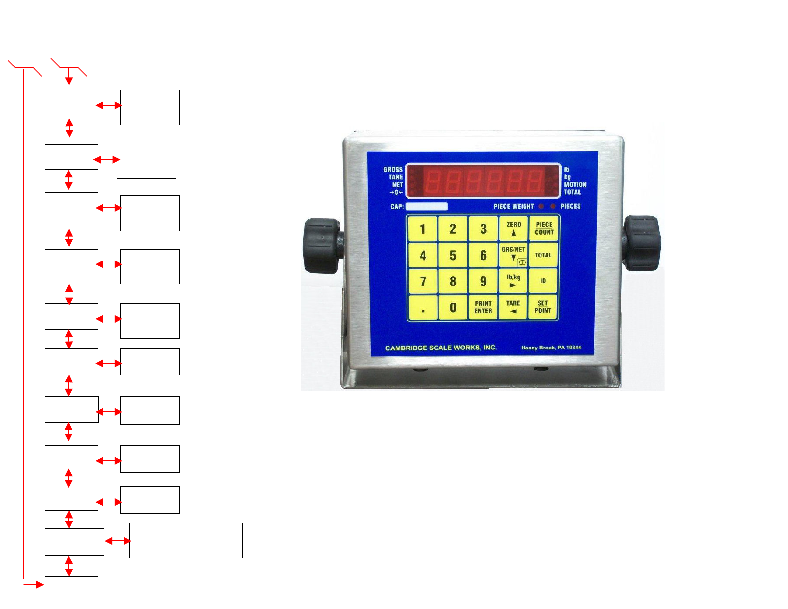
Enter Calibration / Setup mode by pressing and holding the GRS/NET key until Parameter and calibration
event counters are displayed, then release the key. When code is displayed, enter in sequence TARE,
lb/kg, GRS/NET, and PRINT/ENTER. ScAlE will be displayed. Press the down arrow key to enter the
scale menu. Press the right arrow key to enter each sub menu.
-P xxx, C xxx are event counters that will increment each time one or more changes are made
to the Scale or Calibration Parameters.
S1 Ntep 0 Non-Ntep mode 20,000 maximum division limit and no scale negative tests.
1NTEP mode (Default)
2Angle mode. Press the right arrow key to enter. Use the numeric keypad
to enter the desired selection (0,1, or 2), then press the PRINT/ENTER key to
save and exit. S1 will be displayed.
S2 Capacity 1 to 950,000 pounds. 5000 (Default) Press the right arrow key to enter. Use the
numeric keypad to enter the desired capacity then press the PRINT/ENTER key to
save and exit. S2 will be displayed.
S3 Count By .001, .01, .1, 1, .002, .02, .2, 2, .005, .05, .5, 5. 1(default) Use the up and down
arrow keys to choose the count by. Use the left and right arrow keys to choose the
decimal place, then press the PRINT/ENTER key to save and exit. S3 will be
displayed.
S4 Overload (105%) of the scale capacity. Press the right arrow key to enter. Use the numeric
keypad to enter the desired safe overload then press the PRINT/ENTER key to save
and exit. S4 will be displayed.
S5 Zero Limit 0 1.9%
1100% (Default) Press the right arrow key to enter. Use the numeric keypad
to enter the desired selection (0 or 1), then press the PRINT/ENTER key to
save and exit. S5 will be displayed.
S6 Filter 0 to 7, Where 0 is the fastest response and least filtering and 7 is the slowest
response or most filtering. 3 (Default) Press the right arrow key to enter. Use the
numeric keypad to enter the value, then Press the PRINT/ENTER key to save and
exit. S6 will be displayed.
S7 Motion Band 1 to 99 divisions. The weight display must be stable within the selected number of
divisions for the motion indicator to be turned off. 2 (Default) Press the right arrow
key to enter. Use the numeric keypad to enter the value, then press the
PRINT/ENTER key to and exit. S7 will be displayed.
S8 Motion Delay 0 to 99 updates. The weight display must be within the motion band for the
selected number of updates in order to turn off the motion indicator. 4 (Default)
Press the right arrow key to enter. Use the numeric keypad enter the value, then
press the PRINT/ENTER key to save and exit. S7 will be displayed.

10
2.2 Scale Menu Definitions Continued:
S9 Motion 0 Normal (Default)
Display 1 Blank
2 Dashes
Press the right arrow key to enter. Use the numeric keypad to enter the desired
selection (0, 1, or 2), then press the PRINT/ENTER key to save and exit. S9 will be
displayed.
S10 Zero Band 1 to 99 divisions. The weight display must return to zero within the selected number
of divisions to be considered zero. 2 (Default) Press the right arrow key to enter.
Use the numeric keypad to enter the value, then press the PRINT/ENTER key to
save and exit. S10 will be displayed.
S11 Zero Delay 0 to 99 updates. The weight display must be within the zero band for the selected
number of updates to be considered zero. 4 (Default) Press the right arrow key to
enter. Use the numeric keypad to enter the value, then press the PRINT/ENTER key
to save and exit. S11 will be displayed.
S12 Zero 0 0.5 divisions.
Tracking 1 1 division. (Default)
2 3 division
Press the right arrow key to enter. Use the numeric keypad to enter the desired
selection (0, 1, or 2), then press the PRINT/ENTER key to save and exit. S12 will
be displayed.
S13 Tracking 0 to 99 updates. The amount of time that the display must be within the
Delay allowed graduations before it will automatically be zeroed. 0 (Default) Press the
right arrow key to enter. Use the numeric keypad to enter the value, then press the
PRINT/ENTER key to save and exit. S13 will be displayed.
S14 lb/kg 0 lb/kg (Default)
1 lb only
2 kg only
Press the right arrow key to enter. Use the keypad to enter the selection (0, 1, or 2),
then press the PRINT/ENTER key to save and exit. S14 will be displayed.
S15 Scale ID 1 to 99 Scale ID used in RF link output. 1 (Default) Press the right arrow key and
use the keypad to enter a value, then press the PRINT/ENTER key. S15 will be
displayed.
S16 Brightness 0 to 15. Adjusts the LED display intensity where 15 is the brightest. 15 (Default)
Press the right arrow key to enter. Use the up and down arrow keys to increase or
decrease the brightness, then press the PRINT/ENTER key to save and exit. S16
will be displayed.
S17 Sleep Mode 0 to 30 minutes. The display will turn off after the set time elapses, with no scale
activity. 0 (Default). Press the right arrow key to enter. Use the numeric keypad to

11
2.2 Scale Menu Definitions Continued:
enter the value, then press the PRINT/ENTER key to save and exit. S17 will be
displayed.
S18 Angle Limit 0 to 9 Degrees. 6 (Default). Press the right arrow key and use the keypad to enter a
value, then press the PRINT/ENTER. S18 will be displayed.
S19 Disable 0 All keys enabled (Default)
Keys 1 Pieces disabled
2Total disabled
3 Setpoint entry disabled (setpoint will still function).
4Pieces, Total and Setpoint disabled.
5All keys but ZERO and PRINT/ENTER will be disabled. Press the right arrow
key, and use the keypad to enter a selection (0, 1, 2, 3,4, or 5 ), then press the
PRINT/ENTER key to save and exit. S19 will be displayed.
3.0 CALIBRATION PROCEDURE:
3.1 Calibration Menu Definitions:
C1 Zero All Raw counts, (Pitch and Roll if in angle mode) will be displayed. When ZERO is
pressed an analog zero is done and all calibration span points will be cleared. If the
indicator is in angle mode the Pitch and Roll offsets will also be Zeroed.
C2 Zero Zeroed raw counts, (Pitch and Roll if in angle mode) will be displayed. When
ZERO is pressed an analog zero is done and all calibration span points will NOT be
cleared. If the indicator is in angle mode the Pitch and Roll offsets will be Zeroed.
C3 Span Point The last Calibration weight will be displayed then the actual weight on the scale
will be displayed. If you do not wish to change the span point, press the TARE key
to exit without making any changes. If the displayed weight does not match the
known test weight, use the numeric keypad to enter the correct weight. Press the
PRINT/ENTER key to save and exit. The display will return to C3.
C4-C7 Span Points C4 to C7 are for linearity correction. They can be used in order and in any quantity
or not at all if no correction is necessary C4-C7 may be entered at any time without
effecting the original calibration points. The last calibration weight will be
displayed then the actual weight on the scale will be displayed. If no calibration
weight has been entered at this span point “notset” will be displayed then the actual
weight on the scale is displayed. If the displayed weight does not match the known
test weight, follow the steps described for C3 Span Point on adjusting the weight
and entering the value.

12
3.2 Calibration:
Press and hold the GRS/NET key, as described previously in section 2.2. ScAlE will be displayed.
Press the lb/kg key to move right until CalIb is displayed. Press the GRS/NET key to move down, C1 will
be displayed. Press the lb/kg key to move right, the raw counts will be displayed. With no weight on the
scale and the scale level, press the ZERO key, “0” will be displayed. Press the PRINT/ENTER key to save
the entry. “0” is now entered and the display will return to C1.
Note: With the scale completely level use C1 or C2 to zero the angle. There is no need to
use both C1 and C2
Press the GRS/NET key to move down until C3 is displayed. Press the lb/kg
key to enter. The last calibrated weight will flash then the current weight on the scale
is displayed. Place a known test weight on the scale, with the scale level. Using the
numeric keypad, enter the actual weight and press the PRINT/ENTER key to save and exit. The display
will return to C3.
3.3 Linearity Correction
If Linearity Correction is needed, press the GRS/NET key (from the Calibration
menu) to move down until C4 is displayed. Press the lb/kg key to move right, the last calibrated weight
will flash or “notset” will flash if this point has not been previously set. Next the current weight on the
scale will be displayed. Place a different known test weight (not the same test weight that was used for
C3) on the scale. Using the numeric keypad, enter the actual weight and press the PRINT/ENTER key to
save and exit. The display will return to C4. Repeat these steps for C5, C6 and C7.
Linearity Correction points (C4-C7) can be used in any order and in any quantity or not at all if no
correction is necessary. After calibration is complete you may return to these correction points and make
changes to its value without affecting any of the original calibration points.
3.4 Quick Calibration
I. With no weight on the scale.
A. Enter Setup / Calibration mode as described previously in the beginning
of section 2.2. “Scale” will be displayed.
B. Press the lb/kg key. “CALibr” will be displayed.
C. Press the GRS/NET key until “C2” is displayed.
D. Press the lb/kg key to enter C2. The zero Calibration number will be displayed.
E. Press the ZERO key. “0” will be displayed.
F. Press the PRINT/ENTER key to enter the new zero calibration. “C2” will be displayed.
G. Press the GRS/NET key. “C3” will be displayed.

13
3.4 Quick Calibration Continued:
H. Press the lb/kg key to enter C3. The last span weight will flash, then the current weight
on the scale will be displayed.
II. Place a known weight, as close to the capacity as possible, on the scale.
A. Using the numeric keypad enter the correct value for the known weight.
B. Press the PRINT/ENTER key to enter the new calibration. “C3” will be displayed.
C. Press the TARE key. “End?” will be displayed.
D. Press the PRINT/ENTER key to exit Setup / Calibration mode.
3.5 Quick Calibration Linearity Correction
I. With no weight on the scale.
A. Enter Setup / Calibration mode as described previously in the beginning of section 2.2.
“Scale” will be displayed.
B. Press the lb/kg key. “CALibr” will be displayed.
C. Press the GRS/NET key until C4 is displayed.
D. Press the lb/kg key to enter C4. “nOtset” or the last calibrated weight will flash, then the
current weight on the scale will be displayed.
II. Place a known weight on the scale.
A. Using the numeric keypad enter the correct value for the known weight.
B. Press the PRINT/ENTER key to enter the new calibrated linearity correction point. “C4”
will be displayed.
C. Press the TARE key. “End?” will be displayed
D. Press the PRINT/ENTER key to exit Setup / Calibration mode.
If additional Linearity correction points are desired, follow the steps above for C5, C6, and/or C7.
4.0 COMMUNICATIONS SETUP
4.1 Communications Menu Definitions:
R1 Baud Rate 0 1200
COM1 1 2400
24800
39600 (Default)
419200
538400
657600
7115200
Press the right arrow key to enter. Use the numeric keypad to enter the
desired selection (0 - 7), then press the PRINT/ENTER key to save and exit.
R1 will be displayed.
R2 Output 0 Gross, Tare, Net (Default)
Format 1 Weight only
COM1 2Net only
3 Gross only press the right arrow key to enter.Use the numeric keypad to enter

14
4.1 Communications Menu Definitions Continued:
the desired selection (0 - 3), then press the PRINT/ENTER key to save and
exit. R2 will be displayed.
R3 Output 0 Output on command. Standard Print. (Default)
Type Output as selected by R2 Output Format. If “Q” is received
COM1 on the serial port the scale will output the same as if the
print key is pressed. The same holds true for Z = ZERO
U = lb/kg,
D = GRS/NET
T = TARE
1Slave Display output (numeric only) continuous Stx, Six ASCII Characters
(indicated weight), CR, LF (9 Bytes total Output).
2Slave Display output (alphanumeric) continuous Stx, GR, NT, or TR, Six
ASCII Characters (indicated weight), lb, kg, CR, LF (15 Bytes total output).
3RF Link Output.
4 Used for QSI Terminal. Press the right arrow key to enter. Use the numeric
keypad to enter the desired selection (0 - 4), then press the PRINT/ENTER
key to save and exit. R3 will be displayed.
R4 Receiver 0 Disabled (Normal Scale Mode). (Default)
1 Standard Receiver. Receives R3-3 RF Link output string data as it appears on
the scale. All keys are disabled with the exception of the PRINT/ENTER key.
Pressing the PRINT/ENTER key will cause both COM1 and COM2 to print.
If the print command is received from the scale on COM1 the CSW-20 will
print on both COCM1and COM2 (if output type is set to print on command).
2 Remote control. Receives R3-3 RF Link output string displaying data as it
appears on the scale and allows full control of all scale meter functions.
When pressing the ZERO KEY, COM1 will transmit the “Z” command to
the scale.
When pressing the GRS/NET key, COM1 will transmit the “D” command
to the scale.
When pressing the lb/kg key, COM1 will transmit the “U” command to the
scale.
When pressing the TARE key, COM1 will transmit the “I” command to the
scale.
When pressing the PRINT/ENTER key COM1 will transmit the “Q”
command to the scale.
If the print command is received from the scale on COM1 the CSW-20
will print on COM2 (if output type is set to print on command).
R5 Printer Format While R5 is being displayed press 1, 2 or 3 to edit the 3 (30 character)
header lines that will be printed at the top of each ticket. Press 1, r5 1 will
be displayed, then 01 000 is displayed. This is the first character of line 1.
Edit by using the numeric keypad to enter the 3 digit code for the character
of choice (Codes are shown in table 4.1 on the following page). After

15
4.1 Communications Menu Definitions Continued:
entering the code, the display will advance to the next character to be
edited. The left and right arrow keys can be used to go back and adjust
codes that have been entered incorrectly. When the code is entered, press
PRINT/ENTER to save the data. The display will return to R5. Follow these
steps to edit lines 2 and 3. A sample header, footer worksheet, and sample
tickets are shown in figure 4.1 pages 17-19. If a line is cleared, no other
line will be printed below it. An entire line can be cleared by entering the
desired line pressing the ZERO key then press the PRINT/ENTER key. The
display will return to R5 and the line is cleared. While R5 is being displayed
press 4 to edit the footer line that will be printed at the bottom of each
ticket. Use the steps described above to edit this line. If this line is cleared
nothing will be printed.
R6 Baud Rate 0 1200
COM2 1 2400
2 4800
39600 (Default)
419200
538400
657600
7115200
Press the right arrow key to enter. Use the numeric keypad enter the desired
selection (0 - 7), then press the PRINT/ENTER key to save and exit. R6 will
be displayed.
R7 Output 0 Gross, Tare, Net (Default)
Format 1 Weight only
COM2 2 Net only
3 Gross only
Press the right arrow key to enter. Use the numeric keypad to enter the desired
selection (0 - 3), then press the PRINT/ENTER key to save and exit. R7 will be
displayed.
R8 Output 0 Output on command. Standard Print. (Default)
Type Output as selected by R2 Output Format. If “Q” is received
COM2 on the serial port the scale will output the same as if the
print key is pressed. The same holds true for Z = ZERO
U = lb/kg,
D = GRS/NET
T = TARE
1Slave Display output (numeric only) continuous Stx, Six
ASCII Characters (indicated weight), CR, LF (9 Bytes total
Output).
2Slave Display output (alphanumeric) continuous Stx, GR,
NT, or TR, Six ASCII Characters (indicated weight), lb, kg,
CR, LF (15 Bytes total output).
3 RF Link Output

16
4.1 Communications Menu Definitions Continued:
4 Used for QSI Terminal.
Press the right arrow key to enter. Use the numeric key to enter the desired
selection (0 - 3), then press the PRINT/ENTER key to save and exit. R8 will
be displayed.
R9 Time & Date While R9 is being displayed press 1. r9 1 will be displayed, then the date.
To change the date use the numeric keypad to enter the Month first, then
enter the day of the month, and last enter the year. Then press
PRINT/ENTER. The display will return to r 9. While R9 is being displayed
press 2. r9 2 will be displayed, then the time. To change the time, use the
numeric keypad, enter the hour first then enter the minutes (in 24 hr.,
format) and press PRINT/ENTER. The display will return to R9.
TABLE 4.1
LF
010
CR
(sp)
!
“
#
$
%
&
‘
(
)
*
013
032
033
034
035
036
037
038
039
040
041
042
+
,
-
.
/
:
;
<
=
>
?
@
043
044
045
046
047
058
059
060
061
062
063
064
0
048
1
2
3
4
5
6
7
8
9
049
050
051
052
053
054
055
056
057
A
065
B
C
D
E
F
G
H
I
J
K
L
M
066
067
068
069
070
071
072
073
074
075
076
077
N
078
O
P
Q
R
S
T
U
V
W
X
Y
Z
079
080
081
082
083
084
085
086
087
088
089
090
a
097
b
c
d
e
f
g
h
i
j
k
l
m
098
099
100
101
102
103
104
105
106
107
108
109
n
110
o
p
q
r
s
t
u
v
w
x
y
z
111
112
113
114
115
116
117
118
119
120
121
122

17
Figure 4.1
4.1.a Completed Worksheet
Header message work sheet
01
02
03
04
05
06
07
08
09
10
11
12
13
14
15
16
17
18
19
20
21
22
23
24
25
26
27
28
29
30
067
097
109
098
114
105
100
103
101
032
083
099
097
108
101
032
087
111
114
107
115
032
073
110
099
C
a
m
b
r
i
d
g
e
(sp)
S
c
a
l
e
(sp)
W
o
r
k
s
(sp)
I
n
c
01
02
03
04
05
06
07
08
09
10
11
12
13
14
15
16
17
18
19
20
21
22
23
24
25
26
27
28
29
30
049
049
053
048
048
032
066
101
100
102
111
114
099
032
082
111
097
100
032
078
069
1
1
5
0
0
(sp)
B
e
d
f
o
r
d
(sp)
R
o
a
d
(sp)
N
E
01
02
03
04
05
06
07
08
09
10
11
12
13
14
15
16
17
18
19
20
21
22
23
24
25
26
27
28
29
30
067
117
109
098
101
114
108
097
110
100
032
077
068
032
050
049
053
048
050
C
u
m
b
e
r
l
a
n
d
(sp)
M
D
(sp)
2
1
5
0
2
Footer message work sheet
01
02
03
04
05
06
07
08
09
10
11
12
13
14
15
16
17
18
19
20
21
22
23
24
25
26
27
28
29
30
084
104
105
115
032
073
115
032
065
032
051
048
032
067
104
097
114
097
067
116
101
114
032
070
111
111
116
101
114
T
h
i
s
(sp)
I
s
(sp)
A
(sp)
3
0
(sp)
C
h
a
r
a
c
t
e
r
(sp)
F
o
o
t
e
r

18
4.1.b Blank Worksheet
Header message work sheet
01
02
03
04
05
06
07
08
09
10
11
12
13
14
15
16
17
18
19
20
21
22
23
24
25
26
27
28
29
30
01
02
03
04
05
06
07
08
09
10
11
12
13
14
15
16
17
18
19
20
21
22
23
24
25
26
27
28
29
30
01
02
03
04
05
06
07
08
09
10
11
12
13
14
15
16
17
18
19
20
21
22
23
24
25
26
27
28
29
30
Footer message work sheet
01
02
03
04
05
06
07
08
09
10
11
12
13
14
15
16
17
18
19
20
21
22
23
24
25
26
27
28
29
30

19
Figure 4.1.c Sample Ticket
Cambridge Scale Works, Inc.
115 West Mary Street
Cumberland MD 21502
3:45 pm 05/15/2007
Id# 1234567890
Gross(lb): 1200
Tare(lb): 200
Net(lb): 1000
Avg Pc Wt(lb) .500000
Pieces 2000
Weigh From Scale S/N: 07-12730
Figure 4.1.d Sample Ticket
Cambridge Scale Works, Inc.
115 West Mary Street
Cumberland MD 21502
3:45 pm 05/15/2007
Wt# 1 550
Wt# 2 450
Total wt. 1000 lb
Avg Pc Wt(lb) .500000
Pieces 2000
If the average piece weight is 0 then the Average Piece weight and Pieces will
not be Printed on the tickets.

20
5.0 TESTING PROCEDURES
5.1 Testing Menu Definitions:
T1 Software Displays the software version. Press PRINT/ENTER to exit.
Version
T2 Display Flashes all display segments then all indicating Enunciators.
Press PRINT/ENTER to exit.
T3 Keys Press each key to display the row and column of that key.
Press the PRINT/ENTER to exit.
T4 A to D Displays Raw counts where a 1mV/V signal from the scale will display 25,000
counts. When the indicator is in angle mode, Press the GRS/NET key to cycle
Pitch, Roll and Raw counts. Press the PRINT/ENTER Key to exit.
T5 Serial Serial Communications can be verified by connecting pins 2 and 3 on the serial
COM1 port. A single character will be echoed and pass or fail will be displayed. Press the
PRINT/ENTER key to exit.
T6 Setup Data Setup data will be sent out on the printer port.
T7 Default Resets the indicator back to the factory settings. This will clear all calibration and
setup data. “r you sure?” will be displayed. Press the TARE key to exit without
defaulting, or press the print key to reset the indicator to the factory default
settings.
T8 Serial Serial Communications can be verified by connecting pins 2 and 3 on the serial
COM2 port. A single character will be echoed and pass or fail will be displayed. Press the
PRINT/ENTER key to exit.
Table of contents