APPLICATIONS
& SET-UP INSTRUCTIONS:
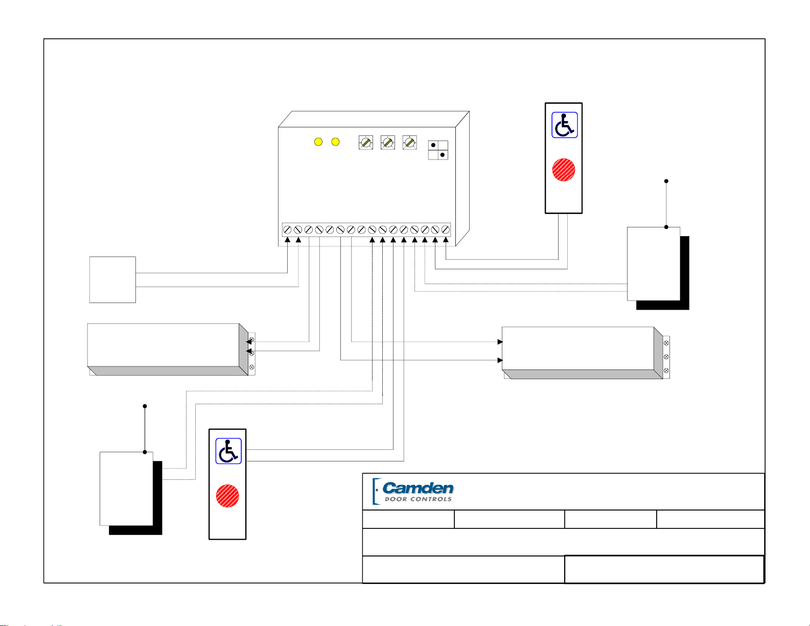
STANDARD TIMER MODE
(Make/Break Relay)
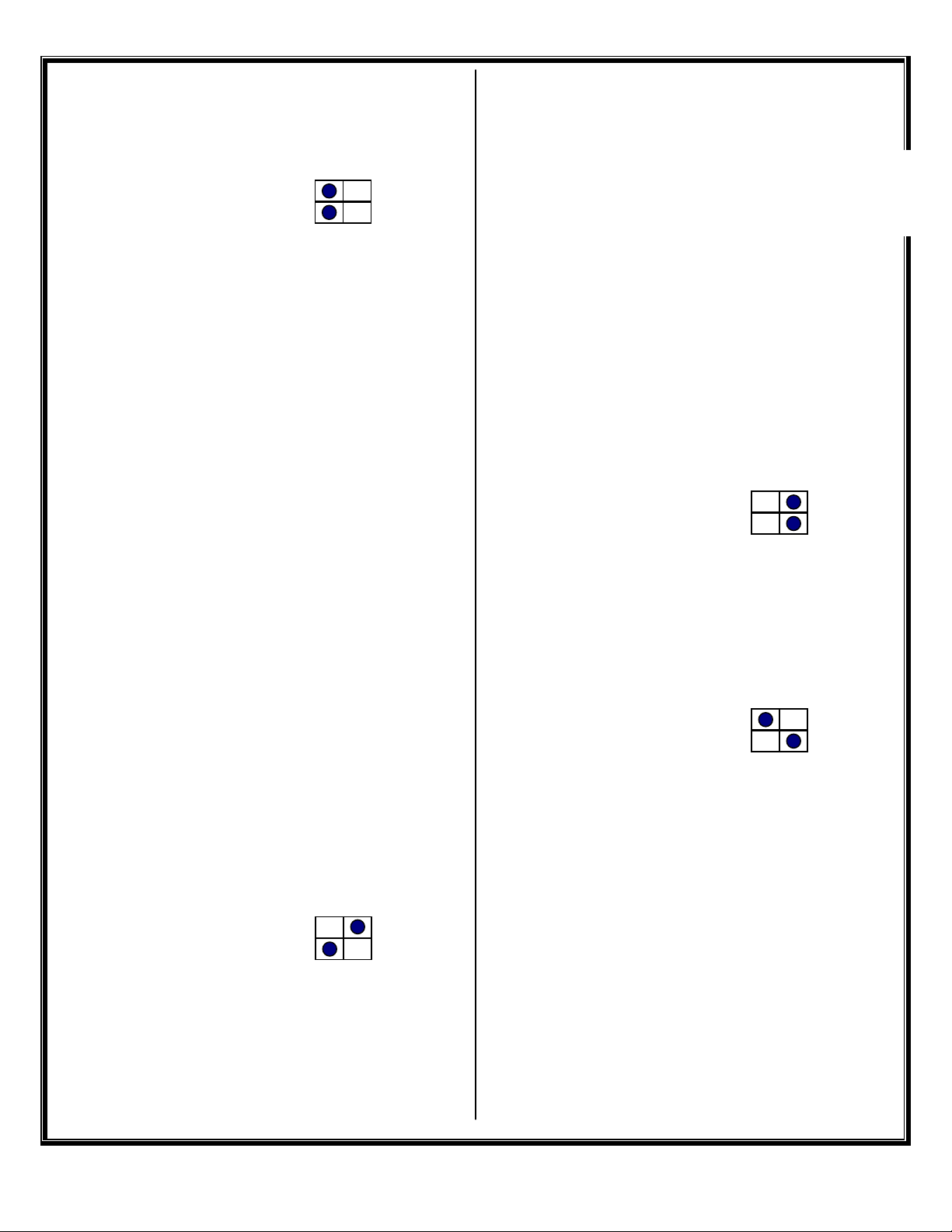
Set dipswitches as shown >
Refer also to Diagram 01.
Connect a dry contact such as a wall switch to DRY1
(Terminals 11 & 12). A Wet (powered) output
connects to WET 2 (Terminals 13 & 14).
Upon a switch activation the strike relay will fire for
the time set by potentiometer 1 (DOR RL1). After a
delay adjustable by potentiometer 2 (DOO RL2) the
operator relay will fire. The hold time for relay #2 is
set with potentiometer 2 (DOR RL2).
Most modern door operators have built-in time
delays, and if so, it is usually desirable to use them to
add sufficient hold-open time. In this case adjust the
CX-29 to send just a momentary pulse (1 or 2
seconds only).
Observe the door and adjust timers until desired
operation is observed.
The above dipswitch setting is also used for
applications such as apartment entries with an
interphone panel. Refer to Diagrams 03a & 03b.
In each case the interphone input (WET 1) will
activate the strike relay only. If a courtesy switch is
located in the vestibule, it is connected to DRY 2
(Terminals 15 & 16). This input is only active when
the strike relay is energized.
Another application using this mode is door
sequencing in one direction only. Connect Door 1
operator to relay 1, and door 2 operator to relay 2.
The delay between the two doors is adjusted via the
DOO RL2 potentiometer. For bi-directional
sequencing refer to specific set-up instructions at
right.
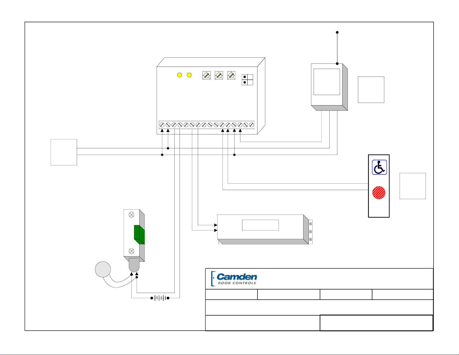
BESAM MODE –with N/O Fire Alarm Input
Set dipswitches as shown >
Refer also to Diagram 02.
Connect the Activating wall switch(es) to DRY 1
(Terminals 11 & 12). This input will unlock and open
the door. The door unlock time is adjusted by
DOR RL1 (note that this timer does not start until the
door closes).
The delay between the lock relay and the operator
relay is adjusted by DOO RL2, and the hold open time
for the operator is adjusted by pot DOR RL2.
Connect the door position switch to DRY 2 (Terminals
15 & 16). The switch can be a magnetic contact
switch on the header, or the HNO terminals on the
CU2 control. Regardless, the contacts need to be
normally open when the door is closed.
The door position switch tells the CX-29 when the
door is open and will not let the locks engage until
AFTER the door has closed.
The WET 2 (Terminals 13 &14) are for a connection
to the Fire Alarm Panel. In this mode we are looking
for a N/O connection. When this contact closes,
Relay 1 turns on immediately, unlocking the door.
The wall switches are ignored. When the Fire Alarm
signal drops out, Relay 1 releases after the time set
by Pot #1, and the door re-locks (but not before the
door closes).
BESAM MODE –with N/C Fire Alarm Input
Set dipswitches as shown >
Refer to Diagram 02.
Similar to previous mode with the following exception:
the CX-29 is looking for a N/C Fire alarm signal.
Connect the Wet (powered) output of the Fire panel
to WET 2 (Terminals 13 & 14). When the fire alarm
input opens, Relay 1 will turn on immediately,
unlocking the door.
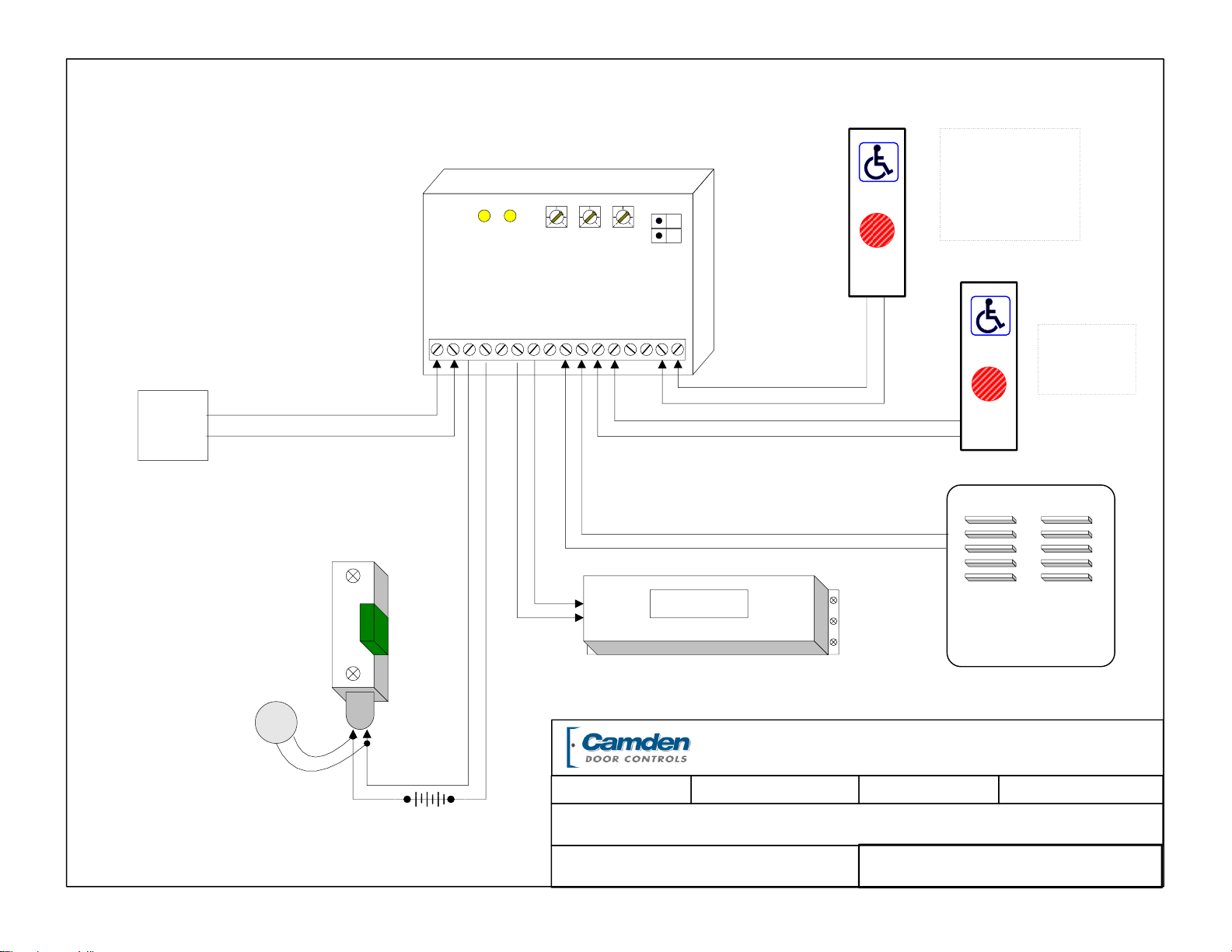
Bi-Directional Sequencing MODE
Set dipswitches as shown >
Refer to Diagram 04.
Turn on power and activate the Interior input (switch).
Observe LED1, which should light immediately. The
length of hold time is determined by adjusting the pot
marked DOR/RL1, clockwise for more time,
counterclockwise for less time.
The delay between the two doors is adjusted via the
DOO RL2 potentiometer.
After the above-mentioned delay, LED2 should light.
The length of hold time is adjusted by the pot marked
DOR/RL2.
The ideal time delay between the two doors is best
set by actual walk-testing. It should be set so that a
person can walk in either direction without having to
pause before the second door activates. Test in both
directions.