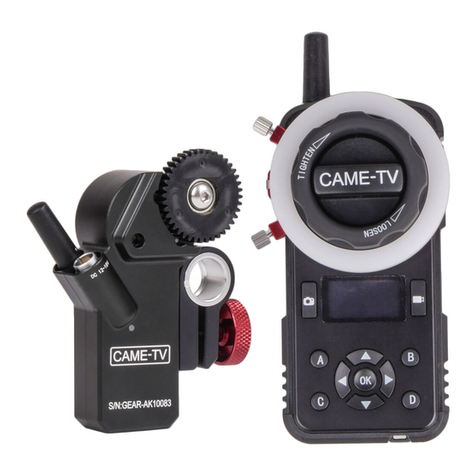
CAME-TV CAME-SINGLE User manual

CAME-SINGLE
User Manual
V1.2
CAME-TV
Customer Support Email
Xiamen CAME Photographic Equipment Co.,Ltd
Tel:+86-592-6283638 Monday to Friday 9:00~18:00 (GMT+8)
www.came-tv.com

Thank you for purchasing the CAME-TV Single. Please read this manual and disclaimer carefully before
commencing use. By using this product, you hereby agree to this disclaimer and signify that you have read it
in full. You agree that you are responsible for your own conduct and any content created while using this
product, and for any consequence thereof. You agree to use this product only for purposes that are proper and
in accordance with local regulations, terms and any applicable polices and guidelines.
Do not modify or adjust the CAME-Single’s electronic programming through rmware upgrades or software
alterations. Doing so without direct guidance or permission from CAME-TV personnel can cause malfunc-
tion to your gimbal and can jeopardize your warranty. The CAME- Single has been calibrated before it
leaves the factory. No modication or amendment to the CAME-Single is allowed or needed.
As CAME- TV has no control over customer use, setup, nal assembly, modication or misuse, no liability shall
be assumed nor accepted for any resulting damage or injury. By the act of use, setup or assembly, the user
accepts all resulting liability. CAME- TV assumes no liability for damage(s) or injuries incurred directly or
indirectly from the use of this product.
Any part of this disclaimer is subject to change without prior notice.
Please contact us if you have any question or problem regarding the proper use of this product.
More information can be found at http://www .cametvblog.com/category/faq
320
195
186
(Unit:mm)
Roll Motor
Yaw motor
Pitch Motor
52.5
86.5
1
Disclaimers and Warnings
1 click is follow yaw and follow tilt mode.
2 clicks is follow yaw and lock tilt mode.
3 clicks s lock yaw and lock tilt mode (No follow movements).
The Single comes already programmed with 3 pre-set factory modes. Simply follow the instructions below to
toggle between them. (Note: An audible chime after button press will conrm mode change)
Maintenance
3. Functions Introduction
4. How to use the Single’s working mode button
8
The CAME- Single is a precise machine and it is not water resistant. Keep it away from sand and dust during
usage. After use, it is recommended to wipe the CAME- Single down with a soft dry cloth. Never spray any
cleaning liquids onto the CAME- Single.
[1]Joystick for direction control
[4] USB Connector
[7]Power on/o
P8
[6]mode switching
(For the PID and software changes)
[2] Battery Indicator
Green--full battery
Yellow--Alert power enough
Red-- Need urgent charge
(The power switch is also the battery power switch\
long press for 3 seconds and the gimbal power will
turn on or o)
Slide the button (Up,down, left ,right)
to control the gimbal’s pan & tilt
movements.
U
D
下
LR
[3]Signal light
(Blue light “ON” when power on)
Camera Size Requirements:
The maximum depth from the center of
gravity on the camera base plate is
86.5mm.
the maximum width from the center of
gravity to the pitch axis is 52.5mm.
Camera and Lens should be within 1Kg.
[5]1/4 screw hole
( for external magic arm to support monitor
or other device)
1/4 screw hole3/8 screw hole
( Bottom of gimbal handle)

2
Contents
Disclaimers and Warnings 1
Gimbal description 1
Contents 2
Packing List 3
Reading Tips 3
Handle Installation
4
Camera Instructions
4
Battery Preparation
5
Balancing Gimbal
Balancing the Pitch Axis 5
Balancing the Roll Axis 6
Balancing Center of the Gravity of the Camera 6
Balancing the yaw Axis 7
How to use the gimbal correctly
Schematic Diagram of all the Axis Limited Angles 7
Function Instructions 8
How to use gimbal working mode button 8
Maintenance 8
User-dened gimbal each axis stable position 7
After the balance, you need rotate it to ensure the Pitch motor does not get stuck. If the vertical
balance needs any necessary adjustment, you may need to balance the pitch axis fore and aft until
the camera stays level at any pitch angle.
1. Loosen the adjustable screw on the Yaw axis handle,then adjust the bracket position (fore or aft) on the
adjustment lever.
2. When proper balance is achieved, you can rotate the camera to any yaw angle and it will stay in that position.
3. Tighten the screw then the balance is complete.
Step 4: Balancing the Yaw Axis
7
1. Schematic Diagram of all the Axis Limited Angles
How to use the gimbal correctly
2. Customizable axis position
Setting method: User can set the gimbal’s customized home position by holding camera
frame at desired position for 3 seconds. Gimbal will automatically record
the revised position as the new starting point of the axial.
Do not go beyond the limited angles when using, otherwise the gimbal will be broken.
Yaw Axis Yaw Adjustable Screw
Adjustment Lever
Bracket
200°
90°
340° 65°

Packing List
Reading Tips
Main gimbal body x 1set
Battery Charger
Gimbal Handle x1
Quick Release Plate x1
1/4”Camera Screw x1 Euro travel adapter
Symbols :
Matters Need Attention Lead to the Related Information Page
3
1. Loosen the adjustable screw on the xed plate, to balance the camera (left or right).
2. When the proper balance is achieved, the camera will stay level after you remove your hands.
3. Tighten the screw.
Step 2: Balancing the Roll Axis
1. Position the camera at an angle (Attention: within the lens at limited range), loosen and adjust the vertical
screw.
2. When proper balance is achieved, you can rotate the camera to any angle and it will stay in that position.
3. Tighten the screw.
Steps 3: Balancing center of gravity of the camera
Screw for Vertical Balance
Vertical Adjustable Screw
Fixed Plate Roll Adjustable Screw
Pitch Adjustable Screw
Fixed
Plate
6

4
Top Handle Installation
Top mount
Bottom mount
Quick Release Clamping
open
closed
1. Open the quick release clamp.
2. Insert the top mount into bottom mount.
3. Close the quick release clamp and check that it is secure.
Camera Installation
Please be sure that the camera sits well on the quick release plate, then attach the QR plate to the
xed plate.
1/4 screw
Quick release plate
1. Attach the quick release plate to your camera using the 1/4" screw,make the adjustment according to the
camera center of gravity.
2. Attach the xed block to the xed plate and insert the quick release plate with the camera into the xed plate
engaging the dovetail and then slide the camera back while pressing the release button to allow the camera
to slide into the xed plate (See picture 2 for arrow direction).
3. Balance and use the handle adjustment screw to x the quick release plate.
Fixed Block
Fixed Plate
Handle Adjustment Screw
quick release button
Pic 2Pic 1
Balancing Gimbal
To achieve the best performance from the CAME- Single, proper balancing is necessary and a must. Accurate
balance is critical in shots where the CAME- Single will be subjected to extreme movements or accelerations
(running, horseback riding, biking, car mounts, helicopters, etc.) Proper balance will also oer a longer
battery runtime . There are 3 axes that need to be accurately balanced prior to powering the CAME- Single
on and setting up the software. Visit http://www.cametvblog.com/category/faq for videos on how to
properly balance your gimbal.
The camera needs to be fully setup with all accessories prior to installing and balancing the camera
on the gimbal. If you are balancing camera with a lens cap on, be sure to remove the lens cap prior
to balancing. Be sure whenever balancing the camera that the CAME- Single’s power is turned o.
1. Loosen the adjustable screw of the handle on the xed plate, and use the xed plate chute to balance the
camera forward and backward.
2. After well balanced adjustment, feel free to pitch (tilt) the angle of the camera. If balanced correctly, it should
hold steady in any corresponding tilt position.
Step 1: Balancing the pitch Axis
5
Battery Preparation
Charger Specication
Input voltage support: 100-240V,50/60Hz
Output plug type: 3.5mmx1.35mm DC
Power output: 12V-1000mA
Output cable length: 1 meter
The gimbal comes with a built-in battery, please charge before usage.
1. Connect the charger adapter with socket.
2. Make sure the gimbal is powered o during the charging process.
3. Depending on its current battery life, a full charge can be achieved in 3-4 hours.
The LED indicator light on the charger plug will switch from red to green once the battery is fully charged.
Once charge is complete, disconnect battery charger from gimbal. Do NOT overcharge.
Power button
Charger port
DC12V DC3.5 1.35mm Charger
socket or
adapter
Table of contents
Other CAME-TV Camera Accessories manuals
Popular Camera Accessories manuals by other brands

Primaluce
Primaluce ARCO 2 user manual

Aquatica Digital
Aquatica Digital AD40x instruction manual

Kaiser Fototechnik
Kaiser Fototechnik Tiltall MP-284 operating instructions

Wolf Garten
Wolf Garten 72V Li-ION Power 24B Original operating instructions

Enerdrive
Enerdrive EPL-100BT-12V-SLIM owner's manual

Ikan
Ikan V8PBK-A quick start guide