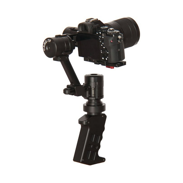
CAME-TV Came-Optimus User manual

MANUAL
V1.1

Parts List
Main body*1 Handle*1
Quick release plate*1 Battery*1
Charger and Adapter*1
M2*6------5PC
M2.5*6----5PC
M3*8------5PC
1/4---------1PC
Screw bag*1
1

1. Fix the camera on the quick release plate using the provided 1/4 camera fixing screw. (photo 1). You could adjust the
camera's position based on the camera's center of gravity
2. Slide the quick release with the camera mounted on it to the fix plate's shute, as shown by the arrow direction in photo 2.
Adjust camera's anterior-posterior (front/back) balance, then lock it by the tightening the lock screw.
quick release plate
Battery Installation: As shown in photo1, please insert the battery onto the gimbal's battery compartment in accordance with
E1 arrow direction. Then push it upwards according to E2 arrow direction to tighten it.
Battery Installation
E2
E1
4
Camera Installation
1/4 screw
handle regulating screw
Photo1 Photo2
When you install the quick release plate on the fix plate, please make sure your camera is fully installed on
the quick release plate firmly.

Step one: Balancing the Pitch Axis
1. Mount your camera onto the gimbal's QR plate. Then slide the QR plate into the fixed plate onto the gimbal. You can
then adjust the camera's anterior-posterior balance via the slide slot on the fixed plate.
2.When fully balanced, the camera will stay level, no matter what (tilt) angle you set it at. Once pitch balance is achieved,
lock the plate in.
Step two: Balancing the Roll Axis
fixed screw 5
Anti-vibration fixed knob
Quick release fixed screw
Optimus Balance Adjustment
To ensure the gimbal functions properly and provides optimal stabilization, balance adjustment is extremely important.
Especially when shooting extreme sports or scenes that involve high-velocity motion (such as running,riding or aerial
shooting, etc.). Exact balance will directly influence the quality of the shooting, and the stabilization of the shot itself.
Proper balance can prolong battery life as well. So before the shooting, be sure to fully balance the gimbal's three axes:
Yaw, Roll, and Pitch axis.You will know you're achieved proper balance if your camera is able to stay level on all 3 axes
whether the gimbal is turned on or off. (If the gimbal is unbalanced on any axis, then it will tilt when the camera is mounted).
Before mounting the camera onto the gimbal, make sure that it is physically in the working state that it will be in when you
start to shoot with it. This means you will need to remove the lens cover, insert the battery, memory card, and any accessories
you wish to mount on it. (Just make sure it's within the specified maximum payload). Balancing the camera first, and adjusting
its supplemental weight second will influence the balance and prevent the gimbal from offering proper stabilization. So make
sure your camera is in full shooting mode before balancing.
Make sure that both the camera and the gimbal are powered off during the balancing process.
1. Loosen the Roll's adjusted screw so that the camera can move left and right.
2. Slowly slide the camera left and right until it can stay level ,and does not tilt to any one side.
3. When fully balanced, the camera will stay level, and will not tilt to any one side.
4. Once roll balance is achieved, tighten the handle screw.

After the balance, you need rotate it to assure the Pitch motor does not get stuck. If the vertical balance needs
further adjustment , you may need to balance the pitch axis fore and aft position again until the camera will
hold steady at any pitch angle.
Screw for vertical balance
Adjustable Screw
Step 4: Balancing the Yaw Axis
1. Loosen the adjustable screw on the Roll axis handle, then adjust the bracket position,(fore and aft) on the adjustment level.
2. When proper balance is achieved, you can rotate the camera at any Yaw angle, and will stay in that position.
3. Tighten the screw to lock it in. If all the steps have been done correctly, then your gimbal should be fully balanced! You
can also visit http://cametvblog.com/category/faq/ for videos on how to properly balance your gimbal.
Bracket
adjustment lever adjustable screw
Customizable axis position
Users can set the gimbal's customizable home position by holding the camera frame at any desired position for 3 seconds.
Gimbal will automatically record the revised position as the new starting point of the axial.
6
Steps 3: Balancing the center of gravity of the camera
1. First of all, if using a zoom lens, make sure it is set to the intended focal length that you choose to shoot at. Once that's
done, set the camera at an angle and then loosen and adjust the vertical screw.
2. Adjust until proper balance is achieved. Once this happens, you can rotate the camera at any angle, and it will stay in
that position.
3. Tighten the screw to lock in its position.

Function Introduction
[2]working indicator light
[3]433remote control pairing
button
[4] USB port
(for the PID and software changes)
[5]1/4 screw hole
(for the external magic arm, monitor and
other accessories)
[6] working modes button
Button for direction control
U
D
LR
3/8screw hole 1/4 screw hole
(for the gimbal support accessories)
7
Sliding the button (up, down, left ,right) to
control the gimbal directions
How to use the gimbal's working mode button (Profiles)
The Optimus comes programmed with 3 pre-set follow modes. Simply follow the instructions below to toggle between
each profile and use its functions. (Note: An audible chime after button press(es) will confirm mode change).
1 click, Follow Yaw and Follow Tilt Mode
2 clicks, Follow Yaw and Lock Tilt Mode (tilting disabled)
3 clicks, Lock Yaw and Lock Tilt Modes (no follow movements)

D
[4] The power switch and mode change button
1. long press the button for around 3 seconds to power one of off the remote controller.
2. 1 quick click will trigger Profile 1, 2 clicks will trigger Profile 2, and 3 clicks will trigger Profile 3.
[2]Charger port
[1] Direction Button
[3] Working indicate light and code button (Pairing)
1.Press and hold the button for 2-3 seconds to complete the code synchronization (pairing process).
Once paired, the indicator light will be green and flash.
2.The green LED light is the signal indicator light. When steady green, the remote is paired and ready to use.
3.The red LED lights are the battery voltage indicator lights. When this appears, it means that the remote is
low on battery and charge is soon needed.
Pressing the button up, down left and right to synchronize the directions with the camera
How to correct use the 433 remote control
L
The 433 remote control is special add-on accessory for the Optimus. It can be used with the gimbal in either
single or dual user operations. The working distance of the remote control is approximately 50 meters.
[1]
[2]
[3]
[4]
U
R
Charge the wireless remote control's internal battery using this port. Approximately 2 hours are needed for a full charge,
which can give the Optimus up to 10 hours of battery life during use.
1.When synchronizing the controller and the gimbal, please be sure that both the gimbal and the controller code
button are long pressed for around 2-3 seconds.
2.The remote controller will go into a standby state after leaving it idle for around 5 minutes.
Pressing the switch will re-power it.
8

APP Bluetooth connection
1.Before connecting:
Please assure the phone has installed the SimpleBGC32 APP application program
Please open the phone's Bluetooth function and turn one the gimbal and then search for the
corresponding available connected device in the phone and tacit approval the device name to CAME-TV.
2. Search for Bluetooth device CAME-TV and click to match it. The password is 1234 (default passwords are all 1234).
3.When the gimbal and phone Bluetooth settings are successfully matched, please click Simplebgc32 APP setting menu.
You can then use the phone APP to adjust the gimbal's all the PIDS settings.
WARNING: Please do not change any settings that you are unaware of. Changing settings you are unaware of can
cause malfunction to your gimbal's operation, and may require you to send it in for repair at your own cost (if under
warranty). Visit http://cametvblog.com/category/faq/ for advise on which settings you can and cannot adjust.
The product extending function:
In the future, the gimbal will have many extending functions with numerous different accessories -
including UAV , dual arm handle, professional cranes/jibs, automotive mounting, mountain bikes,etc .
Stay tuned to http://www.came-tv.com for more information.
360°
360°
360°
9

Battery Preparation
[1]
[2]
[3]
[4]
[4]Battery discharge output port.
[1]Battery Level Indicator ----------------4 LED Lights on the battery indicate current battery level from bottom
to top. (4 lights = 100%, 3 lights = 75%, 2 lights = 50%, 1 light = 25%, 0 lights = empty).
[2]Battery Switch--------------------------Short press shows the current battery power level.
long press for 2 seconds to turn on or turn off.
[3]Battery Charging Port-------------------Connect to provided battery charger.
Battery Charging Port
DC12.6V 500mah Charger
Electric Socket
Charging the Battery
Make sure you fully charge the battery with the provided charger before using the gimbal.
1. Safely connect the charger to an electric socket (110v-240v).
2. Make sure the battery is powered off when connecting to the charger.
3. While charging, the battery level indicator light will flash to show the current battery power level. And at the same
time the LED indicator light on the charger will be red as the battery is charging. Once the battery is full, the
indicator light on the charger will be switch to green, and the battery indicator will turn off automatically.
Once battery is fully charged, please remove the battery and disconnect the charger.
Charger Specification
Input voltage support: 100-240V, 50/60 HZ
Output voltage style: 3.5mm x 1.35 mm DC head inside is positive and outside is negative. Inside (+), Outside (-)
Output rating: 12.6V - 500mAh
Output cable length: 1 meter
2

Instal the Handle Quick Release Connectors
D1 Gimbal's lock catch locating point
D2 Lock catch rotary knob locating point
D3 Handle lock-up locating point
Photo1
Installation: Please connect the handle to the gimbal's main body (via points D1/D2/D3) so that it fits snug and tight, as
shown in photos 1 and 2. Once the body sits flush into the handle, rotate the handle towards the right to
tighten it as shows in photo 3.
Photo2 Photo3
3
Table of contents
Other CAME-TV Camera Accessories manuals