Adjustable Center
Column
Center Column
Locking Sleeve
Angle Lock
Counter-Weight
Hook
Twist Locks Removable
Rubber Feet
Loading Plate
3-Angle
Leg Adjustment
Foldable Leg
1234
7
5
68910
11 12 13 14 15 16
Quick Release Plate Plate-Locking Knob
Ball
Lock Knob
Friction Knob
(BH20/BH30)
Rotating BaseBase/ Rotation Knob
1 2
3 4 5
678
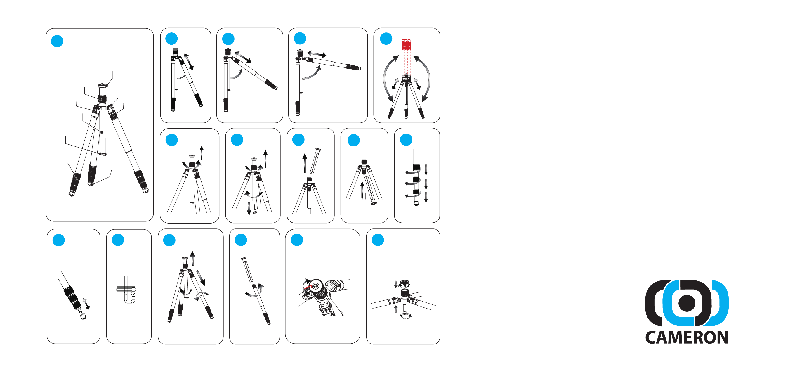
1. (Illustration 1) Recognizing the parts.
2. Leg Angle Adjustment
a. (Illustration 2) High position
b. (Illustration 3) Middle position
c. (Illustration 4) Low position
d. (Illustration 5) Folding up, 180 degree
3. Adjustable Centre Column
(Illustration 6) To unlock the centre column turn the twist knob to the right,
adjust the height of the centre column and lock it by rotating the knob to
the left.
4. Reversible Centre Column
a. (Illustration 7) Remove the spring hook by unscrewing it from the centre
column and then loosen the twist knob for the centre column.
b. (Illustration 8) Remove the centre column by pulling it upwards.
c. (Illustration 9) Reverse the column and insert it through the bottom of the
tripod, then tighten the twist knob.
5. Leg Length Adjustment
(Illustration 10) Turn the twist lock to unlock the leg, adjust the leg to the
desired height. Twist the lock in the opposite direction to tighten the locks.
6. Combined exchangeable spiked system/Detachable Rubber Feet
(Illustration 11) The rubber feet enclose spiked feet. If you need to use the
spiked feet, merely pull the rubber feet off.
7. Spring Hook
(Illustration 12) For added stability when shooting, this hook can be used to
hang a sandbag or equipment bag from.
8. Integrated Monopod
a. (Illustration 13) Remove the leg with the foam pad by rotating it to the left.
b. (Illustration 14) Remove the centre column, (as described in Reversible
Centre Column) and affix the “bottom” of the centre column to the “top” of
the leg that’s just been removed.
9. Macro Shooting (Optional) *does not apply to C500
a. (Illustration 15) Remove the ballhead leaving the loading plate exposed.
Remove the loading plate, along with its camera screw. Remove the
spring hook (as described in Reversible Centre Column) from the bottom
of the centre column.
b. (Illustration 16) Mount the loading plate with the camera screw on the top
of the centre opening securing it by screwing it to the spring hook. Set the
legs to the Low angle (illustration 4) and then mount the ballhead back on
to the loading plate.
*Also, the centre column can be reversed to shoot macro. It is advised to
keep the legs at the High or Middle angle positions if doing such. Use this
method with C500 tripod.
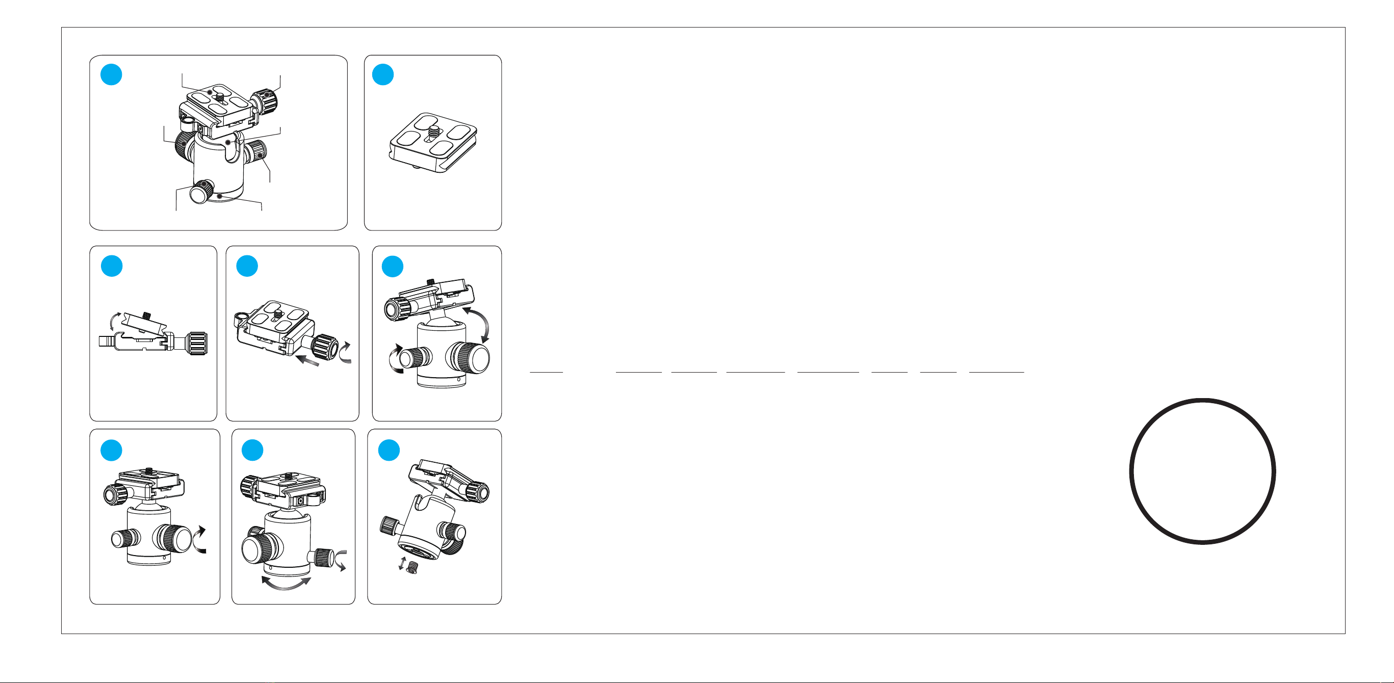
1. (Illustration 1) Recognizing the parts.
2. Mounting the Quick Release Plate
a. (Illustration 2) Mount your camera on the quick release plate, using the supplied, integrated, camera screw.
b. (Illustration 3) Open the plate base, then mount the plate on the clamp.
c. (Illustration 4) Lock the plate by rotating the plate-locking knob to the right until snug.
3. Ball head Operation
a. (Illustration 5) Loosen the lock knob by rotating it to the left. Rotate the friction knob until the desired tension is reached. This
will vary by personal choice and the size and weight of the camera. Ideally the tension will be set such that the camera does
not flop over while adjustments are being made. (Note: the BH10 does not come with a Friction Knob)
b. (Illustration 6) Tighten the lock knob, rotating it to the right.
4. Panoramic Base
(Illustration 7) The base of the ballhead can be rotated through 360 degrees. Loosen the base/rotation knob by turning it to the
left. To lock the base, turn the knob in the opposite direction.
5. Convertible 3/8" to ¼” Nut
(Illustration 8) According to the threaded mounting stud of your tripod, you can choose to use a 3/8" or 1/4" thread nut to mount
the ball head to your tripod. This nut is not included; please ask your Cameron dealer for assistance.
Specifications:
Model Sections Ball Dia. Ext. Height Min. Height Folded Weight Max. Load
CF500 + BH10 5 26mm 1267mm 200mm 320mm 0.73kg 10kg
CF600 + BH20 4 32mm 1437mm 240mm 420mm 0.98kg 10kg
CF700 + BH30 4 38mm 1563mm 270mm 450mm 1.25kg 15kg
Warnings:
Please review and follow the directions of this
manual. Do not exceed any of the specified maximum
load weights. When using the tripod, ensure the
ballhead is locked. Do not leave the tripod exposed to
direct sunlight or in a closed vehicle. Do not operate
this tripod in temperatures below -20°C or above
70°C. It is recommended that this tripod not be
submerged in saltwater. Do not leave this tripod
unattended in public places. Please be careful when
using it in situations that can be considered
dangerous. Remove the camera from the ballhead
during setup or transport. For your safety, keep it
away from power supplies.
YEAR
WARRANTY