CAMPAGNOLO EPS V2 User manual

1 - EPS V2 POWER UNIT (SOLUTION 5)
Depending on which elastic support you have you can secure the V2 power unit to the following seat bracket tubes:
1.1 - POSITIONING INSIDE THE SEAT TUBE WITH ELASTIC SUPPORT IN THE SEAT BRACKET TUBE
ROUND TUBE ELASTIC SUPPORT COLOUR
EXTERNAL DIAMETER 27.9 mm GREY
EXTERNAL DIAMETER 30.9/31.6 mm BLACK
In case of an aerodynamic seat bracket tube (teardrop), select the most suitable elastic support version for the geometry and
dimensions of the tube so that the support is stably inserted.
ASSEMBLY
EPS
1Rev. 01 /10-2016
1
WARNING!
This technical manual is intended for use by professional mechanics.
Anyone who is not a qualified professional for bicycle assembly must not attempt to install and operate on the
components independently due to the risk of carrying out incorrect operations which could cause the components to malfunction, resulting in accidents,
physical injury or even death.

1) Ease the power-off magnet out of the power unit
(Fig. 2).
TOOLS AND ACCESSORIES:
•Cable guide magnet kit SR-RE EPS
•Cable guide magnet kit ATH EPS
OPTIONS AVAILABLE:
•Charging cable extension for EPS V2 Power Unit
•Cable extension for EPS PU installation under the seat (Super Record/Record version)
•Cable extension for EPS PU installation under the seat (Chorus/Athena version)
•Cable extension for EPS PU installation under the seat (Super Record/Record version)
•Cable extension for EPS PU installation under BB (Chorus/Athena version)
2) Fit the noise reducing O-ring provided with the po-
wer unit in the upper cavity (Fig. 3) on the power unit
itself and make the noise reducing spacer adhere on
the lower area of the power unit (Fig. 4).
EPS
43
2
2 Rev. 01 /10-2016

5) Screw the pivot onto the threaded seat at the end
of the power unit (Fig. 7) until it comes into contact
with the nut (Fig. 8).
3) Ensure that the elastic support is compatible with
the seat support tube you have.
4) Tighten the nut (Fig. 5) provided with the support
all the way on the threaded pivot of the support (Fig.
6).
6) Bringing the seat support tube alongside the column tube, in the minimum seat support tube insertion position ensure that
the length of the power unit’s 4 cables is sufficient as shown.
Ensure that the 3 male connectors of the rear derailleur cables (green), front derailleur (yellow) and interface (red) can come
out of the frame holes in order to be connected to the respective female connectors of the components being connected.
Ensure that the connector for recharging the power unit can be positioned in the pre-bored hole on the frame.
If the cables are not long enough procure adequate extensions (see the Tools and accessories table).
• For the rear derailleur (55 cm), front derailleur (55 cm) and interface (135 cm) cables the “Cable extension for EPS PU instal-
lation under seat” kit is available (Super Record/Record or Chorus/Athena version)
• For the single interface cable (25 cm) the “Cable extension for EPS PU under BB installation” is available (Super Record/
Record or Chorus/Athena version)
• For the recharge connector cable (50 cm) the “Recharge extension cable for Power Unit EPS V2” is available
Note
Remember that if the extensions are not used, once the power unit is installed you may not be able to remove the seat support
tube from the column tube. The crankset may need to be disassembled and the power unit of various components may need
to be disconnected.
EPS
3Rev. 01 /10-2016
8
7
56

8) Clean and lubricate the internal surface of the seat
support tube in order to increase adherence between
the tube itself and the elastic support (Fig. 13).
9) Insert the elastic support into the entire length of
the seat support tube (Fig. 14) and, in the event of
an asymmetric seat support tube, determine the best
installation position of the elastic support.
Once the support has been inserted if the support is
too easily extracted return to Step 3.
• Gently turn the male connector of the extension in
the female connector of the power unit to find the cor-
rect alignment between the two connectors, then push
the male connector into the female connector (Fig. 11).
• Fully tighten the outer knurled bush of the exten-
sion connector (Fig. 12).
7) If it is necessary to fit the charging cable exten-
sion to the power unit, follow the instructions below,
otherwise proceed to step 8.
• Undo the nut from the power unit connector and
fit the O-ring included with the extension onto the
connector (Fig. 9).
• Apply and re-tighten the nut (Fig. 10).
EPS
910
11 12
13 14
4 Rev. 01 /10-2016

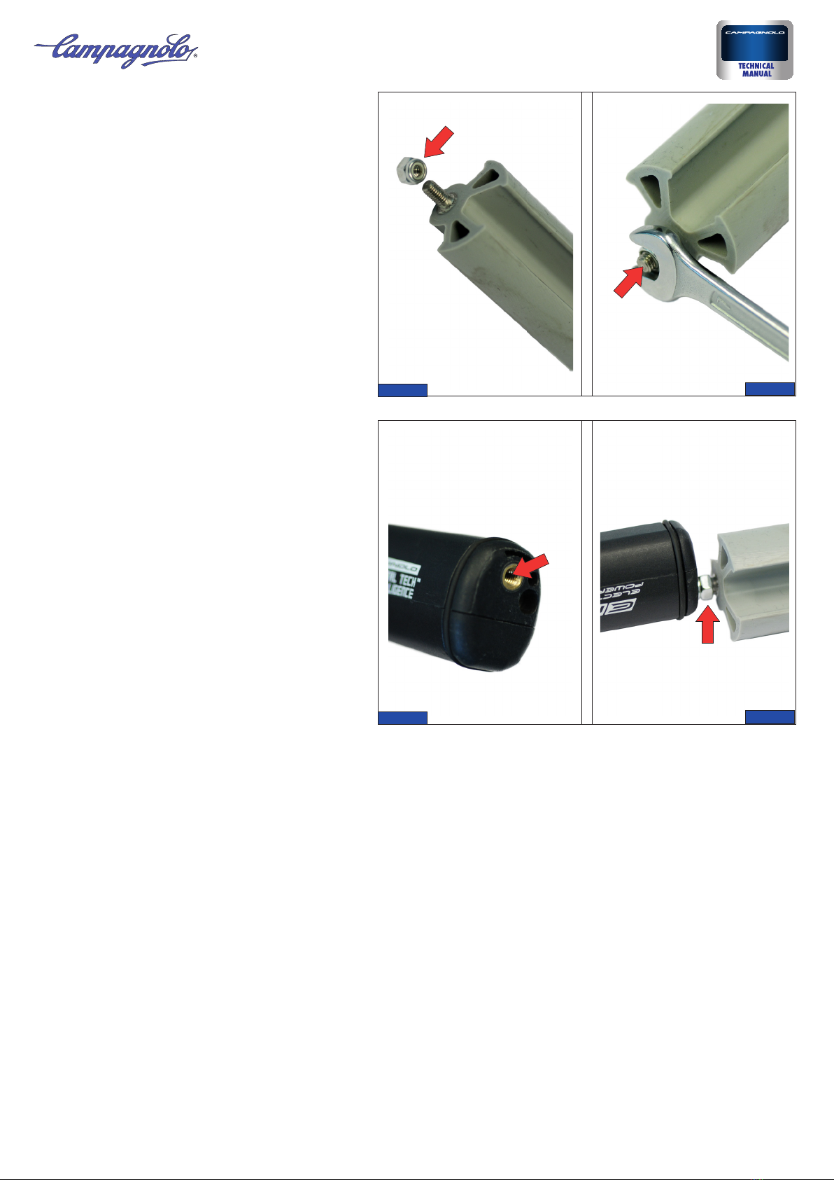
10) Rotate the power unit to the necessary angle, un-
screwing or screwing in the pivot in order to align it
to the column tub and to any encumbrances inside
the frame (for example, be careful of the bottle holder
rivets).
Lock the power unit into defined position tightening
the nut with a 7 mm wrench all the way onto the power
unit to a torque of 2 Nm (18 in.lbs).
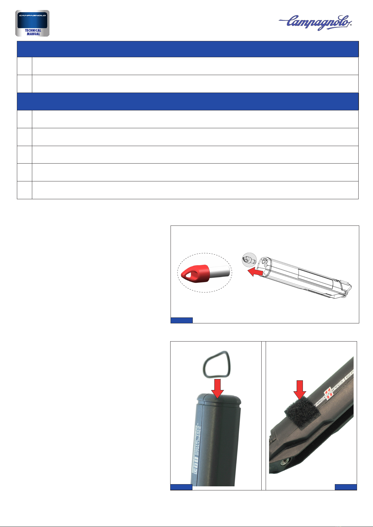
11) To hold the 4 cables of the power unit together
and facilitate routing of the cables through frame, fit
one of the two spiral wraps: near the front derailleur
connectors and the battery charger connector, and fit
the other near the rear derailleur connector (Fig. 17).
Bring the cables out from the bottom bracket shell.
If it is not easy to get the cables out from the bottom
bracket shell, use the grommet magnet kit, putting
the long cable in from the bottom bracket and making
it come out of the seat tube. Fit the short wire on the
red connector, connect the two magnets and pull the
long cable, pulling the ends of the cables out from the
bottom bracket.
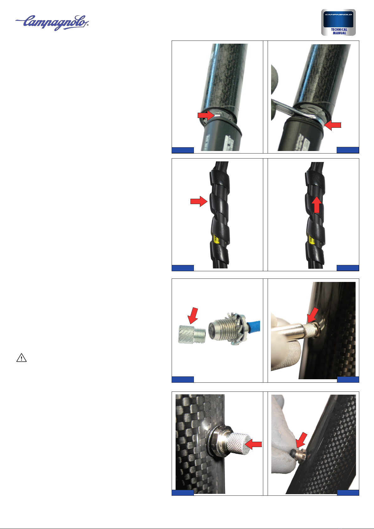
• Remove the spiral wraps holding the cables toge-
ther (Fig. 18).
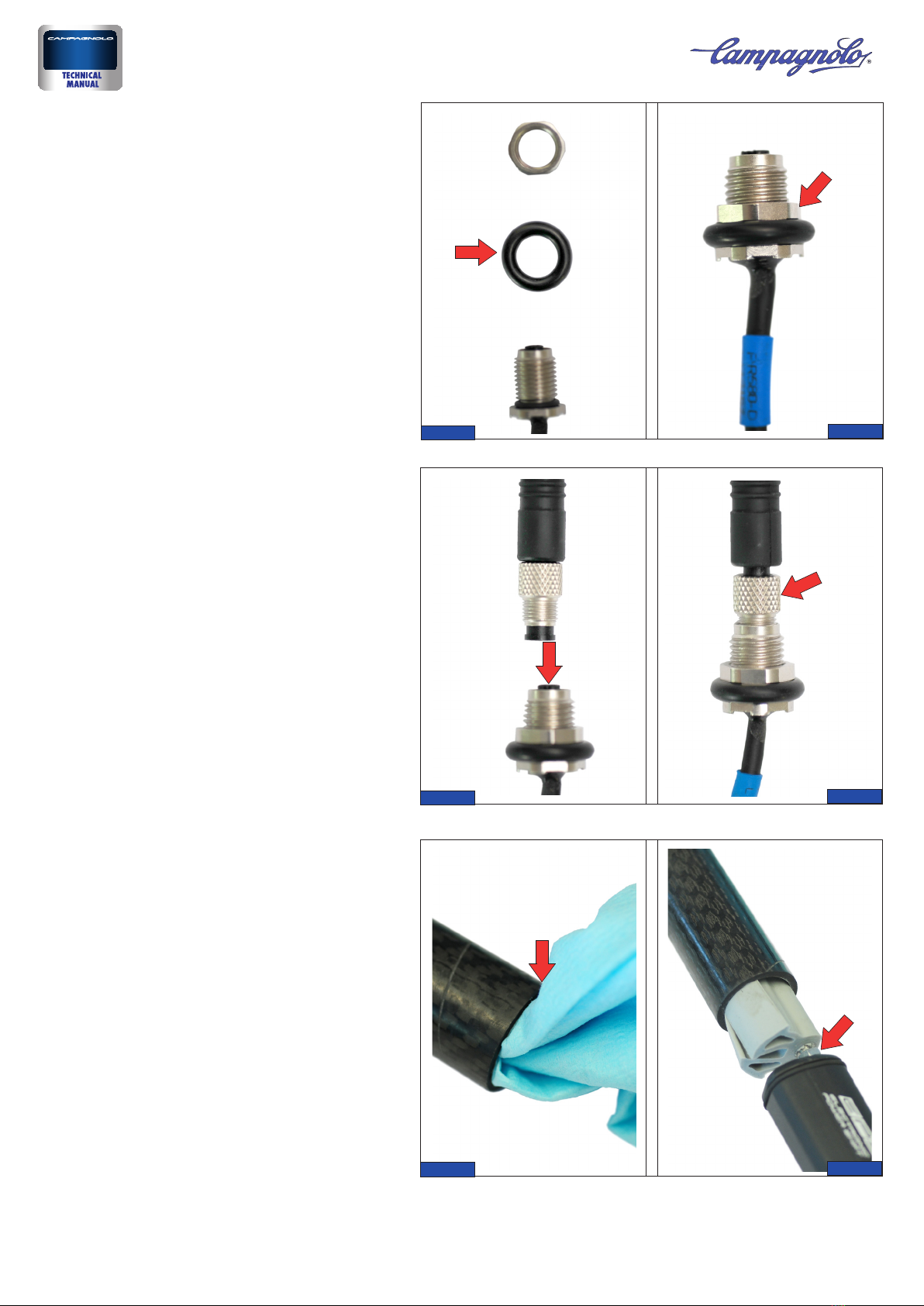
12) Fit the threaded metal insert onto the battery
charger connector (Fig. 19), leaving the knurled wa-
sher on the connector.
- Insert the long cable of the cable guide magnet kit
into the exit hole for the battery charger connector,
then connect it to the battery charger connector with
the magnet.
- Partially bring the connector out through the hole in
the frame and leave the cable with magnet to prevent
the connector from sliding back inside it (Fig. 20)
- Put the washer and nut on and tighten to a torque of
1.5 Nm (13 in.lbs)
(Fig. 21).
WARNING!
If you have a carbon fibre frame contact the frame
manufacturer in order to ensure that it will not be
damaged after tightening to a torque of 1.5 Nm (13
in.lbs) or to define the actions to be taken in order to
prevent damage.
Even the slightest damage caused to a carbon fibre
frame can cause damages which may lead to acci-
dents, injuries or even death.
13) Remove the threaded metal insert (Fig. 22) and fit
the connector cover cap, screwing correctly into place.
EPS
5Rev. 01 /10-2016
15 16
17 18
19 20
21 22

14) Apply the warning label (Fig. 23) on the seat sup-
port pipe to reduce the risk of damage in the event
of disassembly of the seat support pipe (there are 2
labels provided in the package with different colour
text designed for white and black/carbon seat sup-
port pipes).
Continue installation by routing the cables for the rear
derailleur, the front derailleur and the interface, fol-
lowing the instructions given in the chapter “Assem-
bly: cable routing” chapter, available from our websi-
te: www.campagnolo.com.
To determine where to place the Campagnolo sticker
that comes with the power unit and which will indica-
te where to place the magnetic EPS shut-off strip, we
recommend knowing the definitive seat height of the
end customer.
Once established, place the magnetic strip on the co-
lumn tube, approximately near the upper end of the
power unit, up to which the system will be switched
off. Place the rectangular part of the sticker in corre-
spondence with this position.
EPS
23
6 Rev. 01 /10-2016
Table of contents
Popular Portable Generator manuals by other brands

Festo
Festo OVEM-...-1P Series Instructions and Operating

Champion Global Power Equipment
Champion Global Power Equipment 201064 quick start guide

Leroy-Somer
Leroy-Somer LSA Series Installation and Maintenance

Generac Power Systems
Generac Power Systems GP3300 owner's manual

RGC
RGC HydraPaks HH1358C instructions

Husky
Husky HU22511 Operator's manual